We needed a small PCB to securely mount our 12×12 mm push button, so we cut a section from the PCB breadboard using a sheet metal cutter. This trimmed piece serves as the switch PCB.
The push button was positioned at the center of this PCB. The board was then flipped over, and the button leads were soldered in place using solder wire.
2
ELECTRONICS SETUP
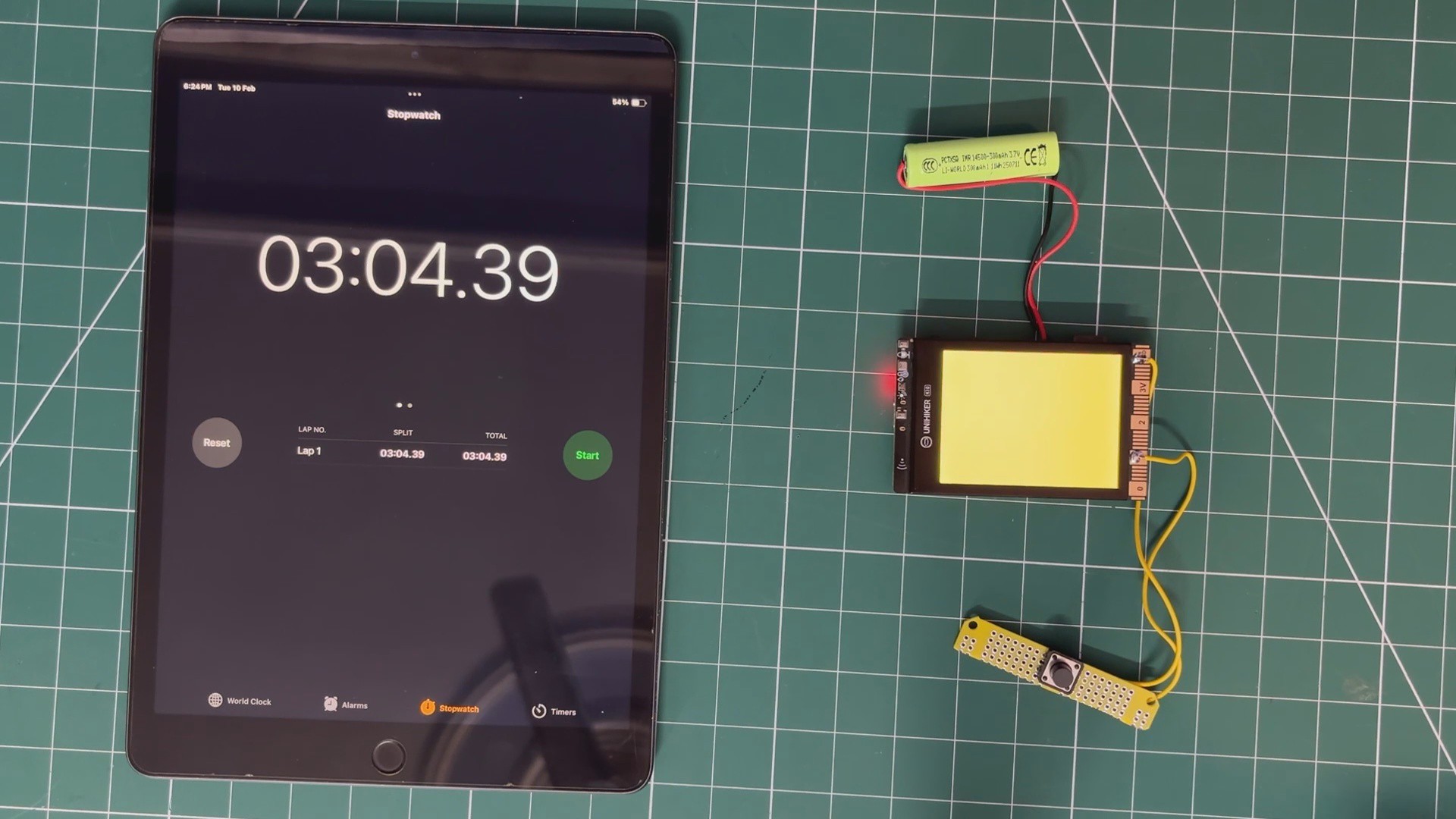
The main electronics assembly comes next. Two connecting wires were soldered to the switch terminals. Through these wires, the switch PCB was connected to the GND pin and Pin 1 of the UNIHIKER.
Next, a 3.7V 600mAh lithium cell was connected to the battery terminals of the UNIHIKER. This will serve as the primary power source for the device.
3
Preparing GIF
Now comes one of the most critical parts of this project: the animated GIF.
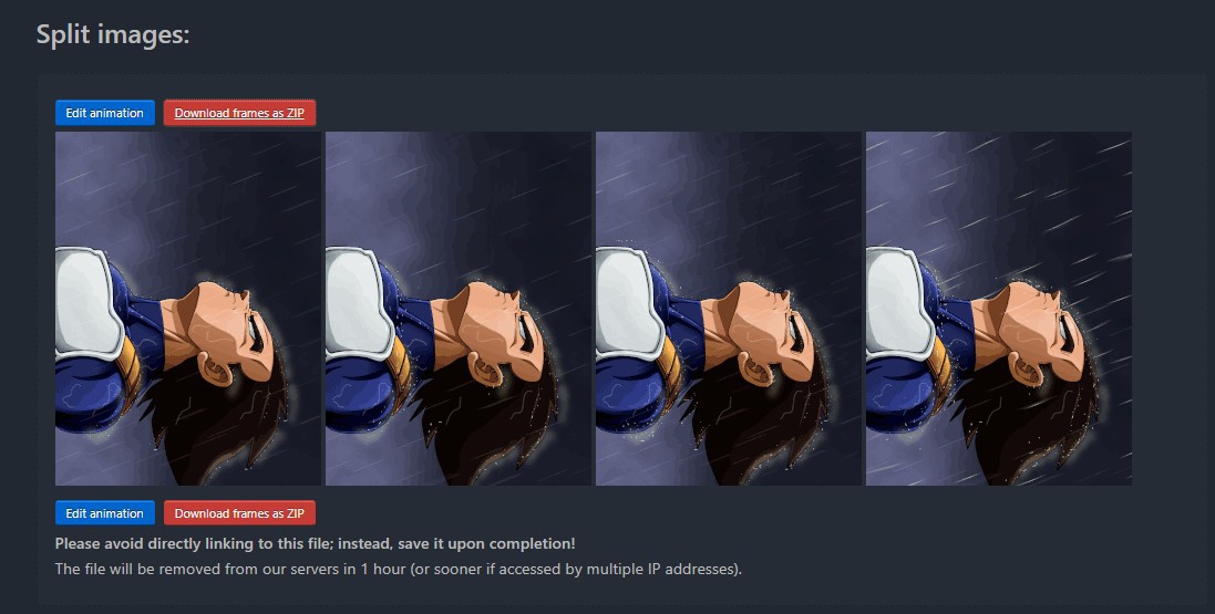
Initially, I selected a short looping GIF of Vegeta standing in the rain.
Ideally, the process would be simple: place the GIF file on the SD card and let the UNIHIKER play it directly. However, the UNIHIKER does not support native GIF playback. It can only display static images stored on the SD card.
To work around this limitation, I used EZGIF to process the animation. First, the original GIF was resized to 320×240 pixels to match the UNIHIKER’s display resolution.
Next, the GIF was split into individual frames. Each frame was exported in JPG format.
The idea is straightforward: instead of playing a GIF file, we rapidly display multiple JPG frames in sequence. By cycling through these images at a fixed frame rate, we simulate motion and recreate the animated effect.
4
UNIHIKER K10 CORE INSTALLATION
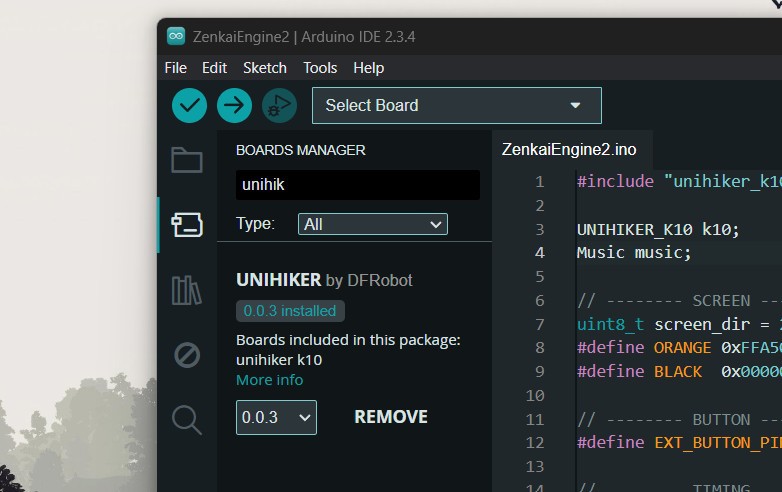
Before uploading the code to the UNIHIKER, we first need to install the Arduino core for the UNIHIKER K10 by following the installation guide provided on DFRobot’s official wiki.
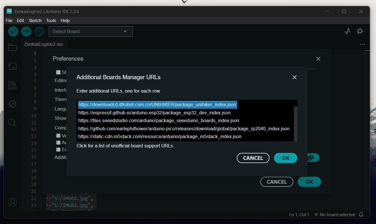
We copy and paste the provided board manager URL into the Additional Board Manager URLs section in the Arduino IDE settings.
Next, we open the Boards Manager, search for UNIHIKER K10, and install the required board package. Once installed, this allows us to select the UNIHIKER K10 from the board selection menu in the Arduino IDE.
5
MAIN CODE & DEMO
Here's the code we used in this build, and it's a simple one.
Aside from the code, we used an 8GB SD card formatted in FAT32. Inside the SD card, we added four images named IMG01 to IMG04, along with an audio file named WAVE01 These files are accessed by the UNIHIKER during playback to render the animation and play the motivational speech.
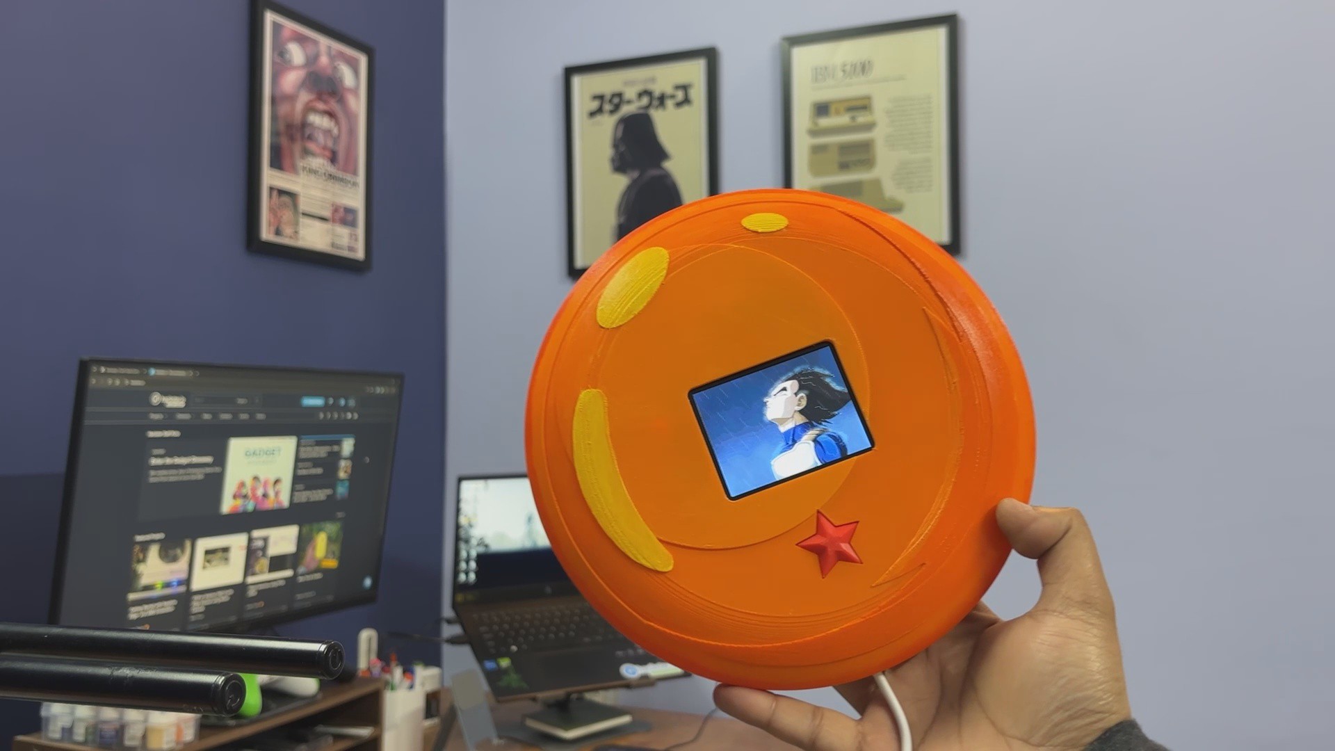
When we power on the device, the display shows an orange idle screen to match the color of the enclosure. When the button is pressed, the device starts the playback sequence, in which images are rapidly cycled to create the illusion of animation while simultaneously playing a WAV audio file.
Once the one-minute sequence completes, the system returns to the orange idle state. If no interaction occurs for three minutes, the display turns off to conserve power. When the button is pressed again, the screen turns orange and the device is ready for playback. This entire setup operates continuously in a loop.
We have attached a small short that shows playback; do check it out for a demo.
6
DESIGN
After finalizing the electronics, we moved on to the enclosure design. We could have made a simple enclosure to hold the UNIHIKER in place, but that would have been boring. Since we are using Vegeta as our motivational character, we wanted something that could house the UNIHIKER while also looking visually striking. The obvious choice was a Dragon Ball, not just any Dragon Ball, but the larger Namekian Dragon Ball from Planet Namek, which is bigger than its Earth counterpart.
Unfortunately, I was not able to create a fully spherical enclosure. For now, I designed only the front portion thick enough to house the UNIHIKER, the switch PCB, and the battery inside.
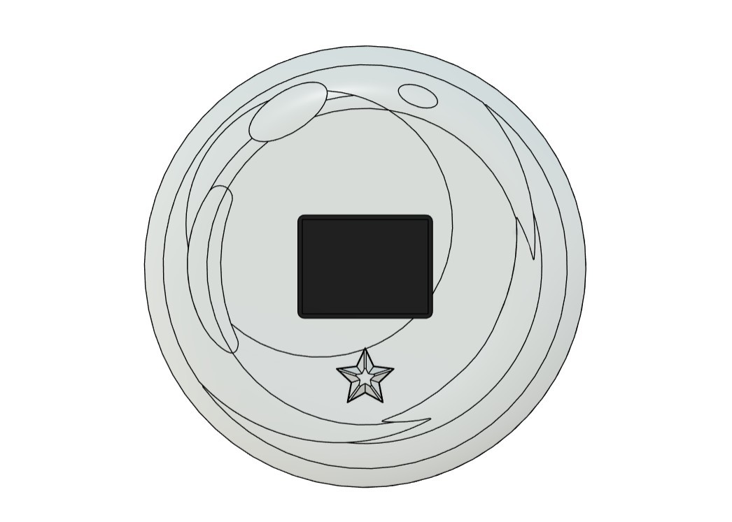
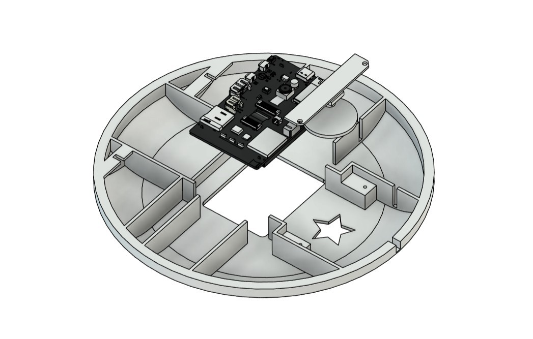
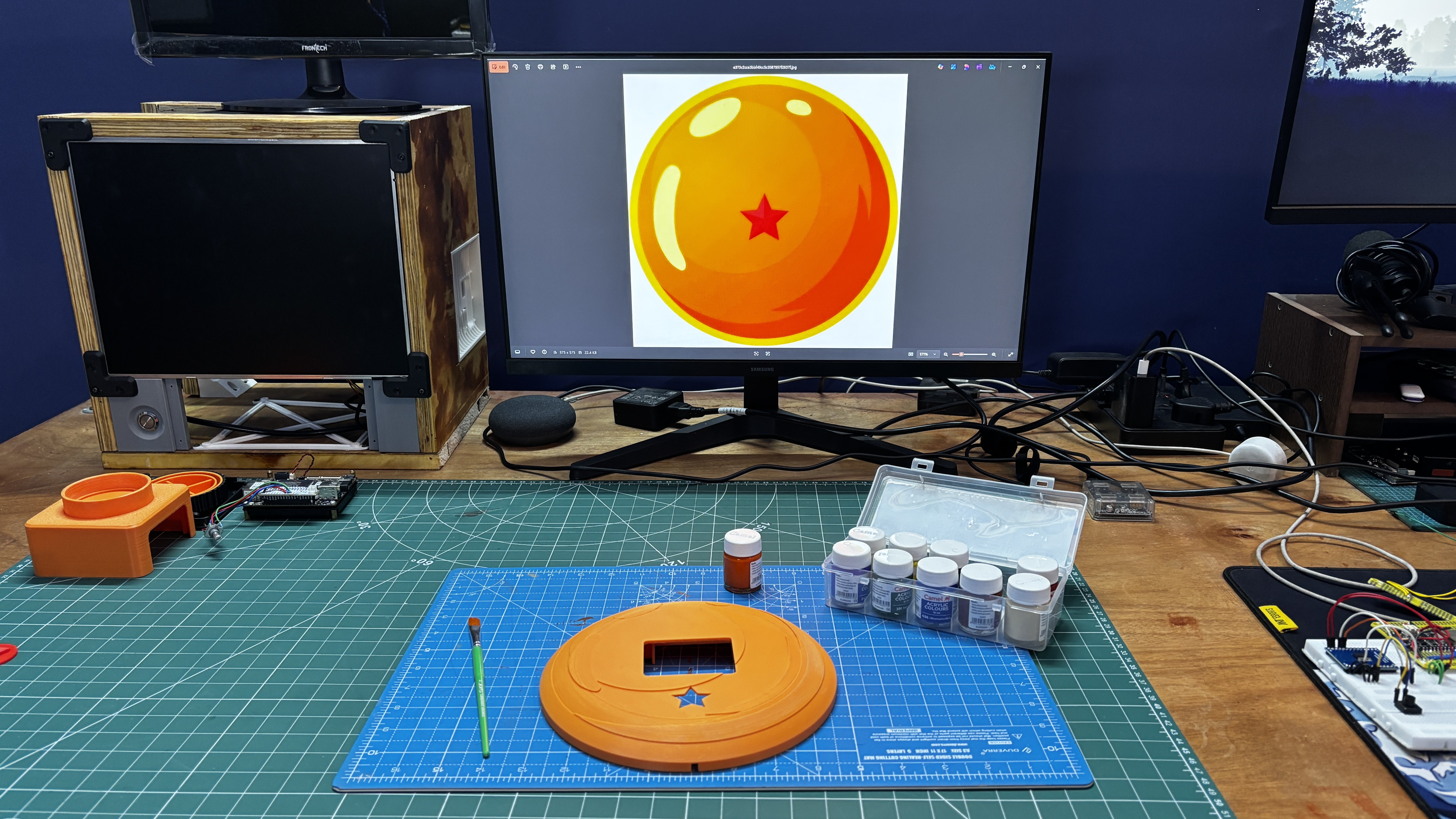
We used Fusion 360 to model the Dragon Ball. A clear front-facing image of the Dragon Ball was imported using the canvas tool and calibrated to a diameter of 202 mm. The outline of the ball was carefully traced, then hollowed out to create space inside. The UNIHIKER was positioned centrally within the enclosure, and a window was created so the screen would remain visible from the front.
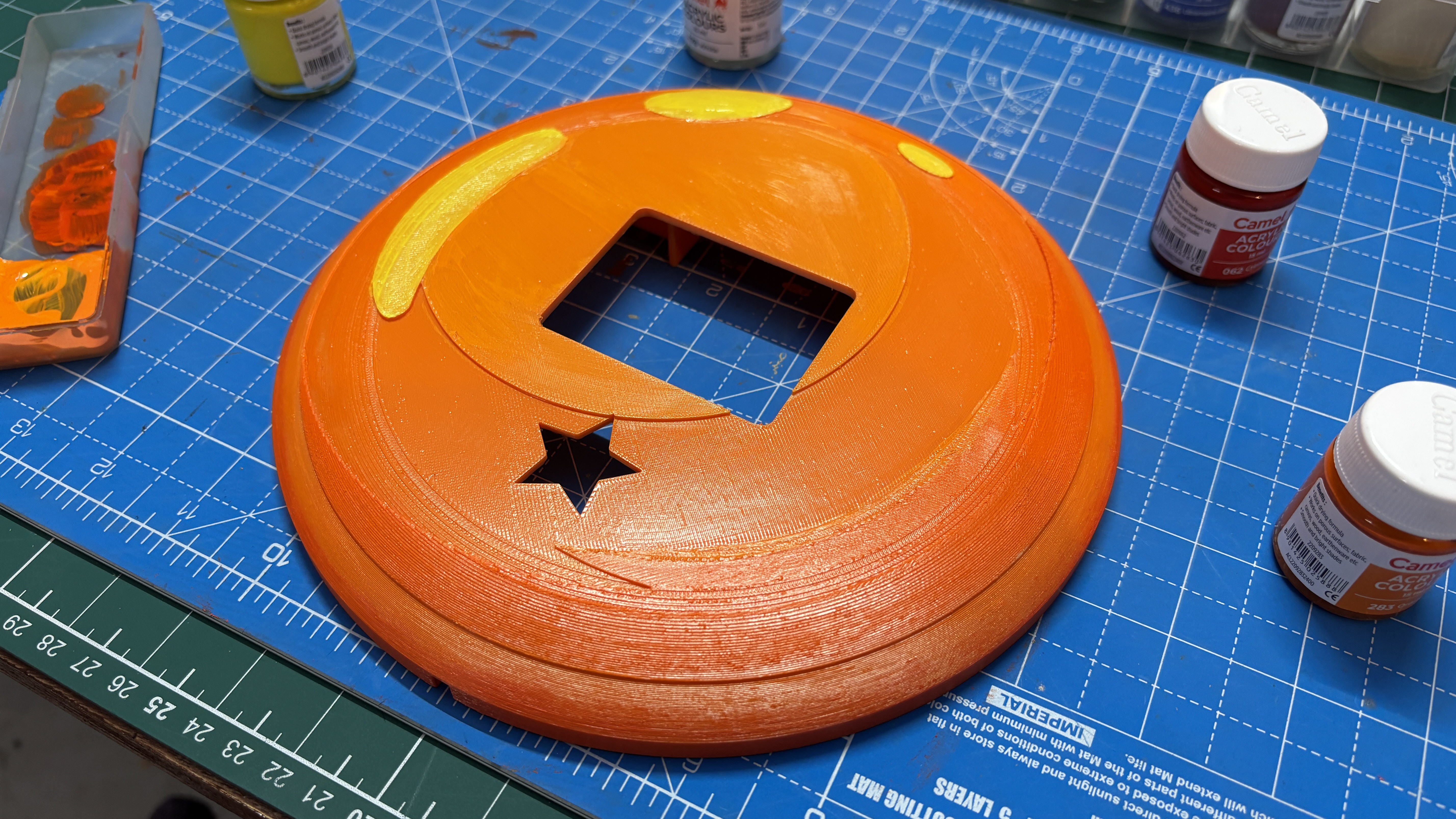
Below the screen, a single star was modeled by tracing its outline. This star serves as the external button. Directly beneath the star, we placed the switch PCB so that pressing the star would mechanically actuate the switch, which the UNIHIKER registers as a button press.
To secure the switch PCB in position, two mounting holders were modeled inside the enclosure. The switch PCB is attached using two M2 screws, ensuring stability and proper alignment.
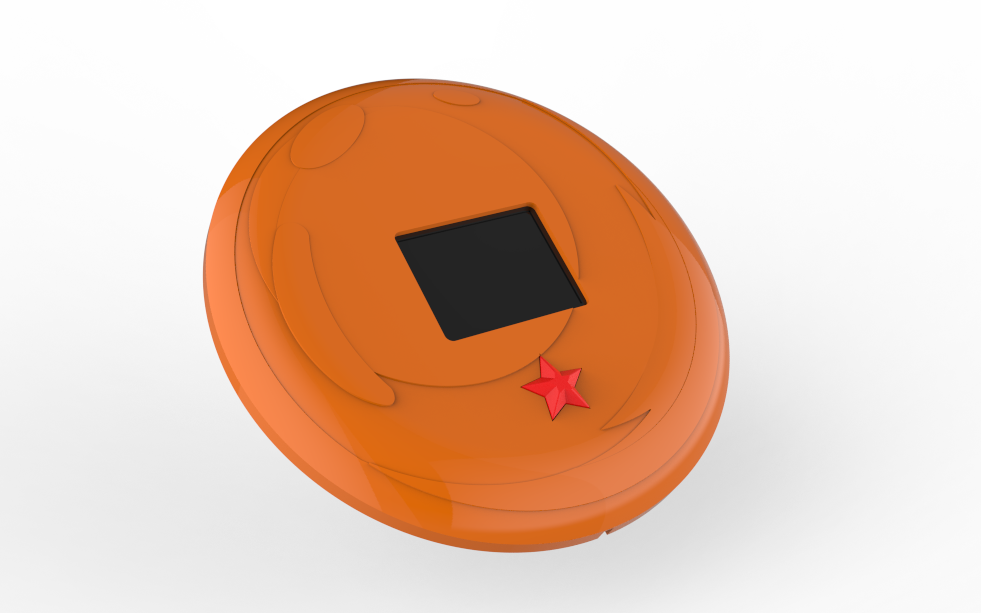
The entire design was built around maintaining the aesthetic of Dragon Ball. No extra elements such as rocker switches or visible hardware were added that would disrupt its original look.
After finalizing the design, we exported the mesh files for both the Dragon Ball enclosure and the button. The Dragon Ball was printed using Orange Hyper PLA with a 0.16 mm layer height and 25% infill. We used normal supports with a snug support type, which allowed the support material to be removed easily without applying excessive force.
Similarly, the star button was printed using the same settings, with the only change being the filament color, switching from orange to red.
7
PAINT
We printed the Dragon Ball using orange PLA, which already matched the base color of the Dragon Ball. However, the original Dragon Ball has subtle highlights and shading that give it a glass-like appearance. A single flat orange print did not capture that effect.
To recreate the original color palette, we decided to paint the enclosure. We used orange acrylic paint as the base and mixed in small amounts of yellow to create lighter tones and red to produce darker shades. This allowed us to manually build depth and highlight areas to mimic the natural reflections seen on the Dragon Ball.
Using a 5 mm brush and a reference image of the Dragon Ball, we hand-painted the front surface. The result was a significantly improved finish that looks much closer to an authentic Dragon Ball, except for the glossy glass-like shine.
This step was entirely optional and not required for functionality, but it was important to achieve a more accurate and visually appealing final result.
8
ASSEMBLY PROCESS
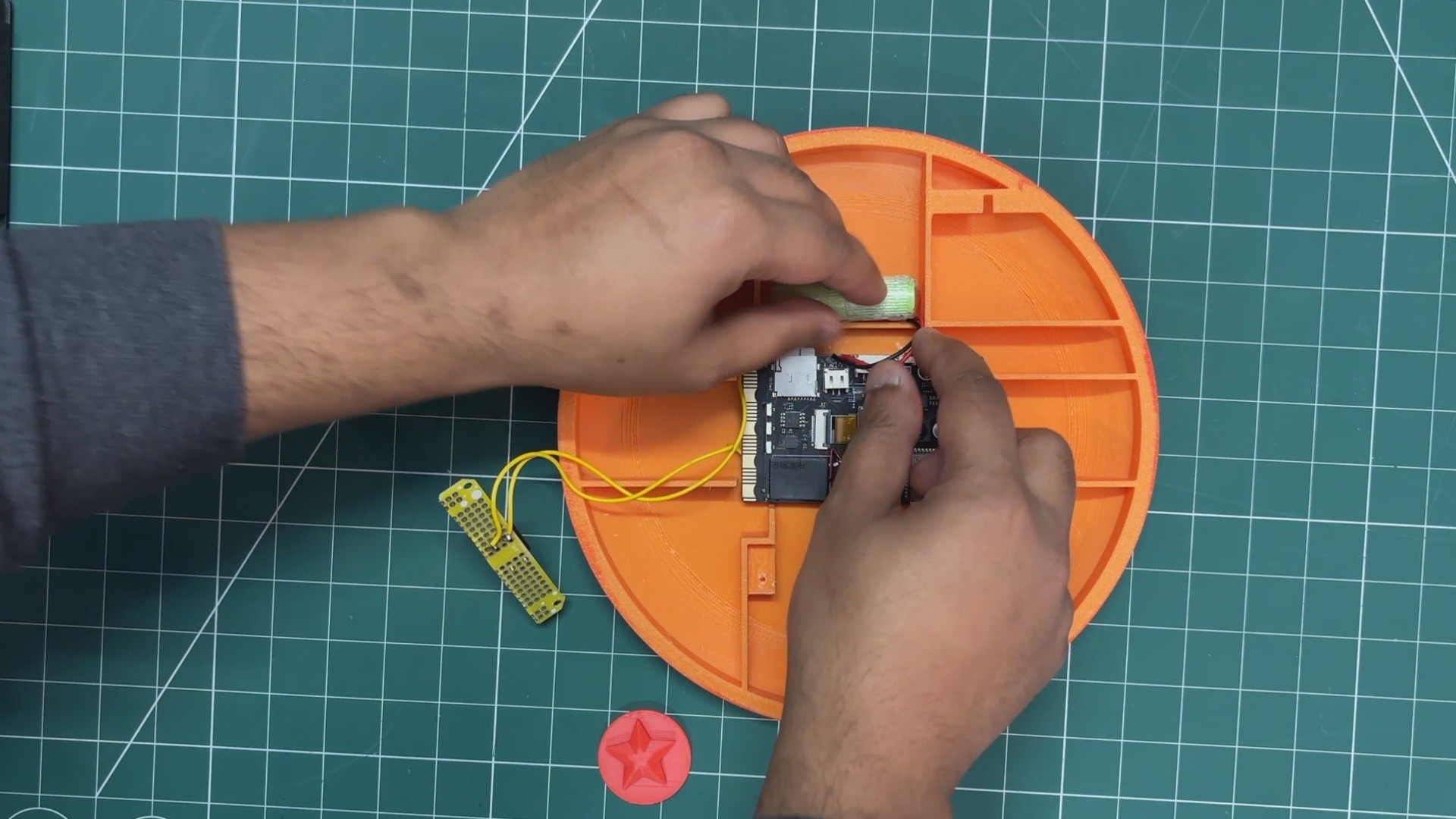
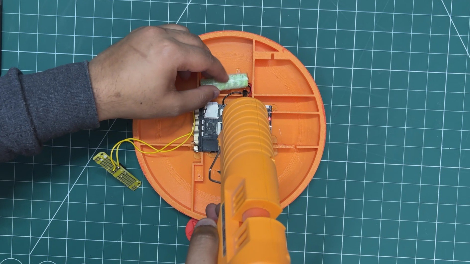
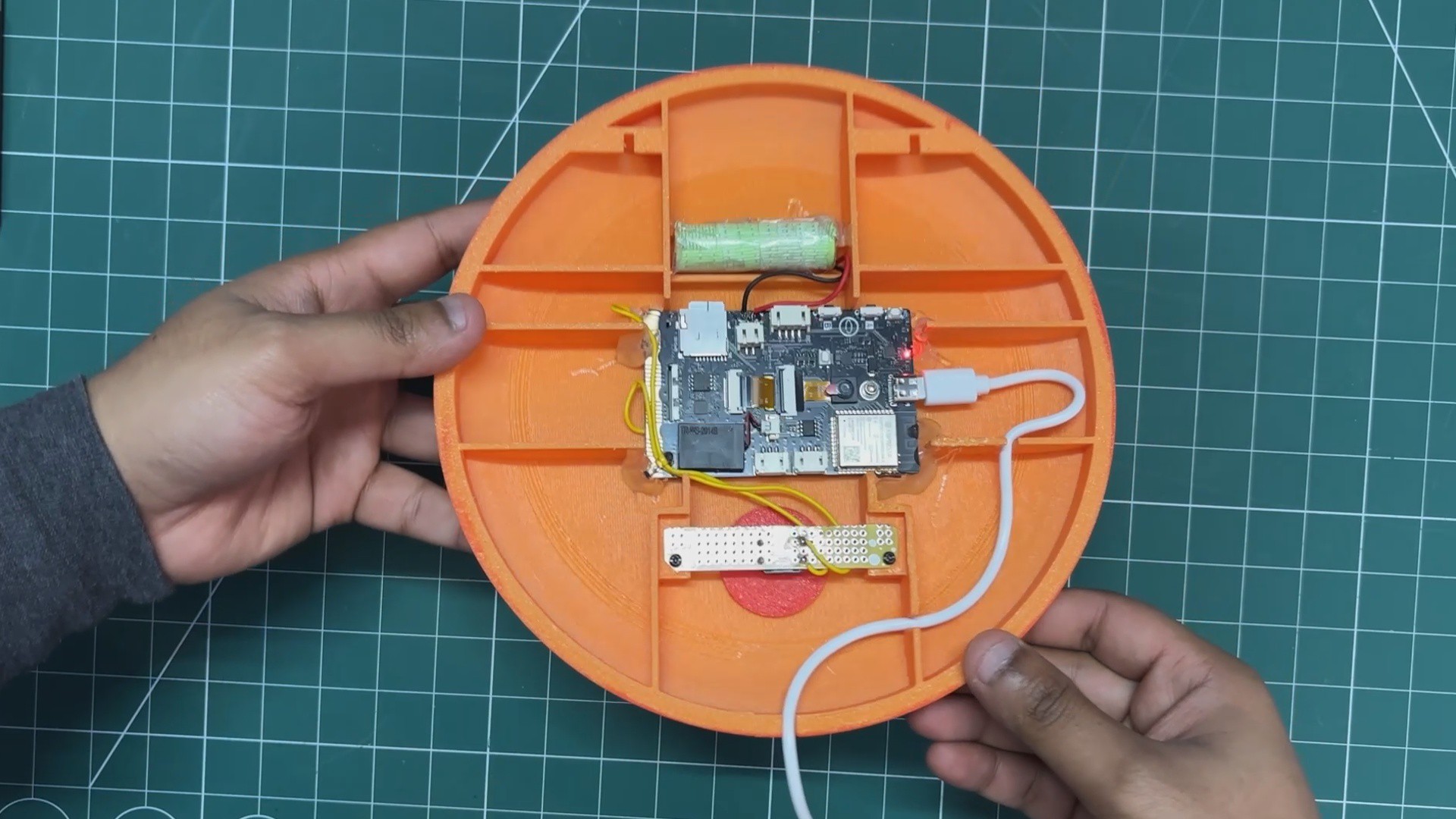
First, the UNIHIKER was placed inside the enclosure in its designated position, followed by positioning the lithium cell above the UNIHIKER.
Hot glue was used to secure the UNIHIKER in place by applying it along the edges of the board. A small amount of hot glue was also applied to the lithium cell to keep it firmly fixed in position.
Next, the star-shaped button was inserted from the inside of the enclosure. The switch PCB was then positioned directly above the star button and secured in place using two M2 screws.
Finally, a 3-meter USB Type-C cable was connected to the UNIHIKER. The enclosure includes internal ribs with dedicated slots that allow the cable to pass through neatly and exit from the bottom of the device.
This USB cable is connected to a 5V charger to power the system continuously. In the event of a power outage, the internal lithium battery automatically powers the device.
With this, the assembly process of our Zenkai Engine is complete.
9
RESULT
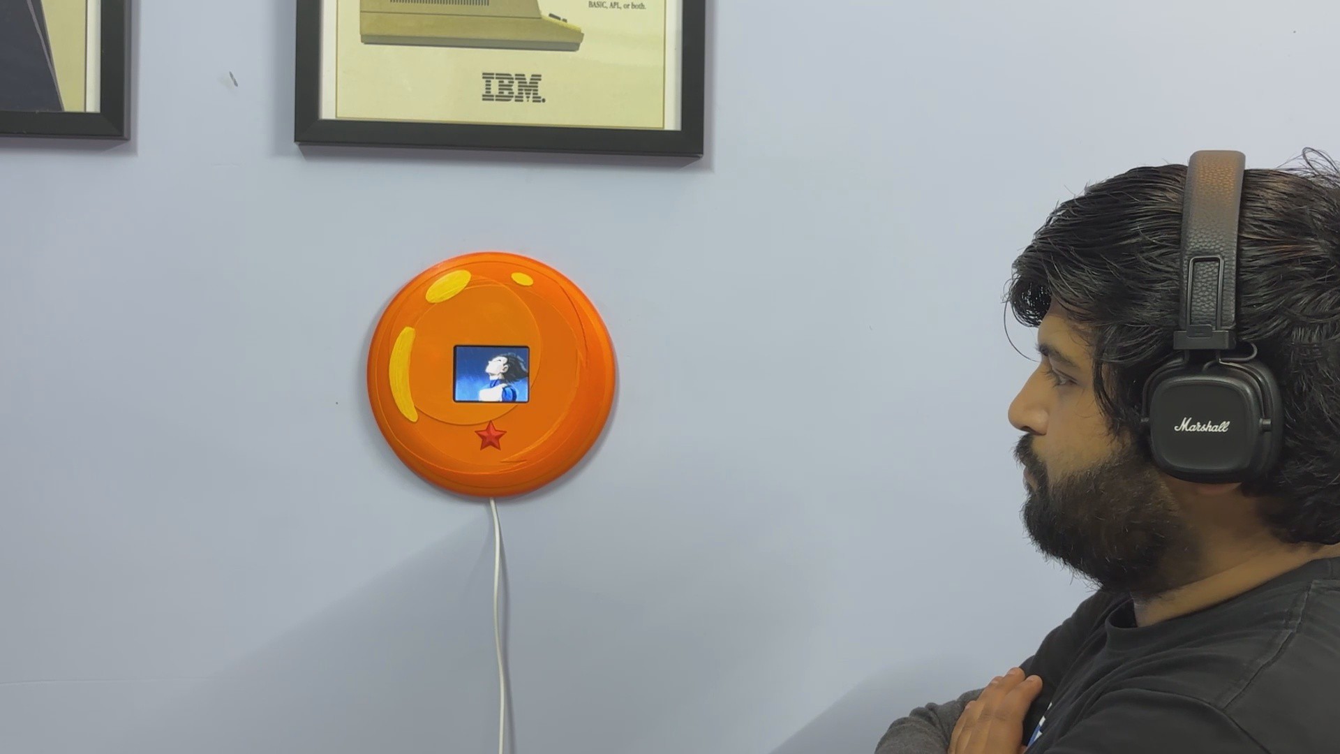
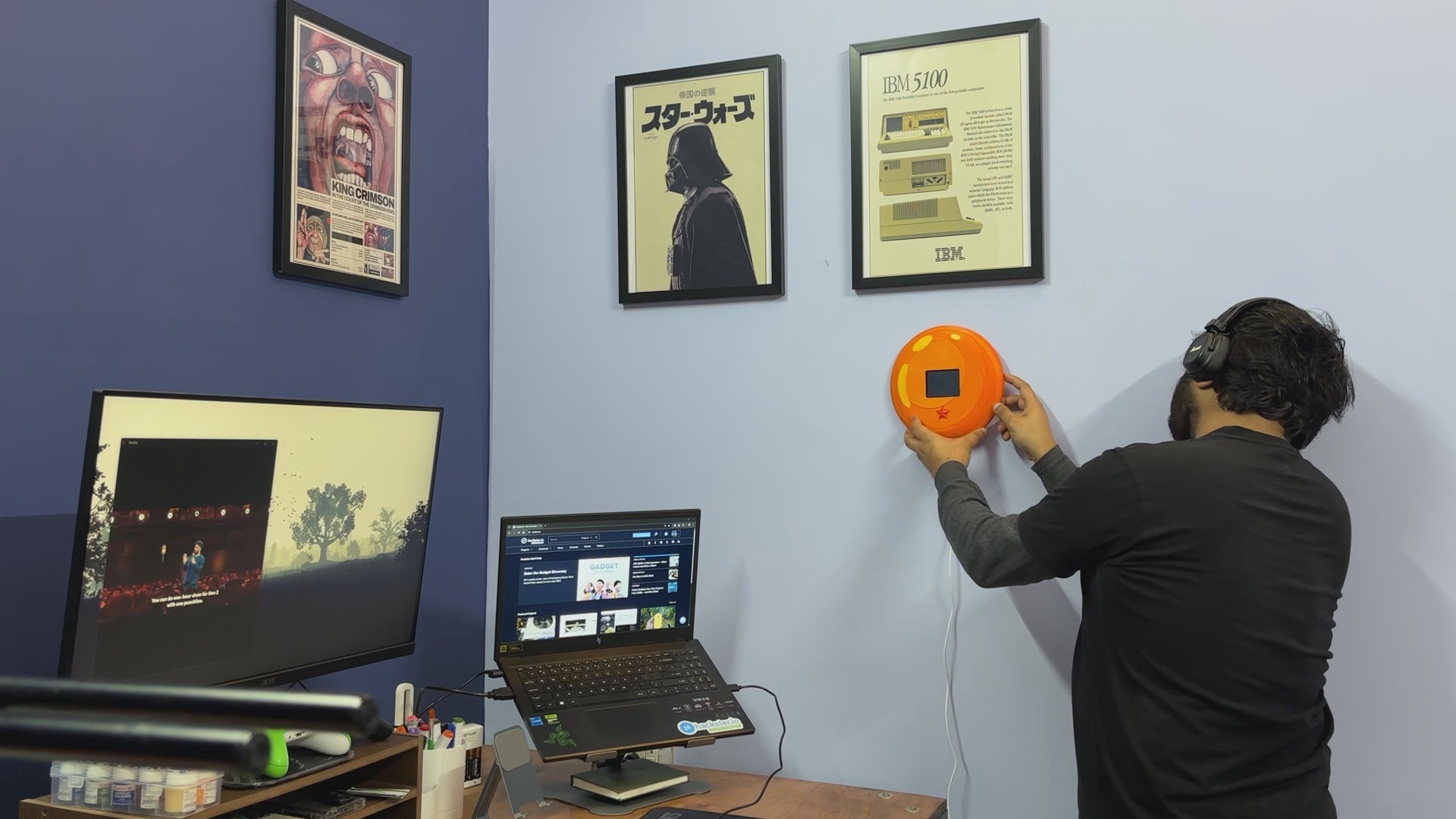
To mount the device, we placed two nails on the wall, allowing us to hang the Dragon Ball securely near the workstation where I spend most of my time. It is positioned on the right side of where I sit, making it easily accessible whenever I need it.
Whenever I feel demotivated or stuck on a problem, I simply press the star button. Vegeta’s voice plays through the Zenkai Engine, delivering a short burst of motivation that helps reset my mindset and push forward again.
When not in use, the device automatically turns its screen off after a few minutes to conserve power. A single press of the button brings the display back to life with the orange idle screen, which indicates the system is ready. Pressing the button again starts the full playback sequence, triggering both the animated display and the motivational audio.
The Zenkai Engine is more than just a decorative piece. It functions as a physical reset switch for my mindset, a reminder that frustration is part of growth. Instead of walking away from a problem, I now have a ritual: press the button, refocus, and return to work.
Mounted beside the workstation, it blends into the environment as a Dragon Ball, but its purpose goes beyond aesthetics.
Special thanks to HQ NextPCB for providing components that I've used in this project; check them out for getting all sorts of PCB or PCBA-related services for less cost.
All the details are covered in this article—feel free to reach out if you need any help regarding the project.
 Arnov Sharma
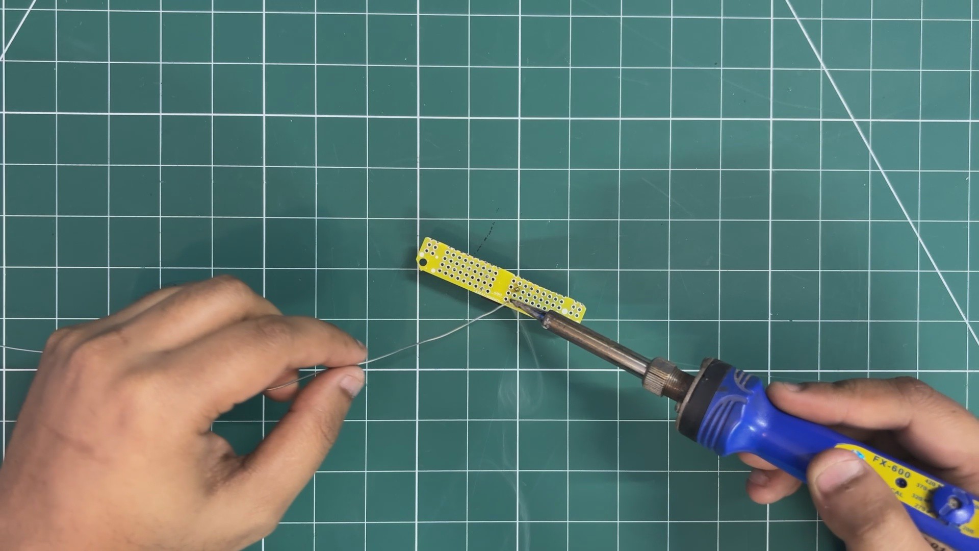


Discussions
Become a Hackaday.io Member
Create an account to leave a comment. Already have an account? Log In.