 alisa.wu
-
1Instructions for turning the device on and off
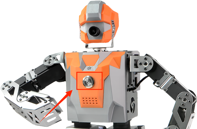
a. Locate the circular main power switch on the chest of the SamuRoid humanoid robot.
b. Press the switch lightly to turn it on. Once powered on, the switch will illuminate with a red indicator light, signifying that the power is connected.
![]()
c. Please wait patiently for approximately 40 seconds while the robot's built-in Ubuntu operating system starts up.
d. When you hear the voice prompt "Mech Warrior ready!", it means the robot has entered standby mode and is ready for operation.
-
2Shutdown Procedure
When shutting down, the robot will lose its power balance. Please be sure to hold the robot firmly to prevent it from falling and being damaged.
-
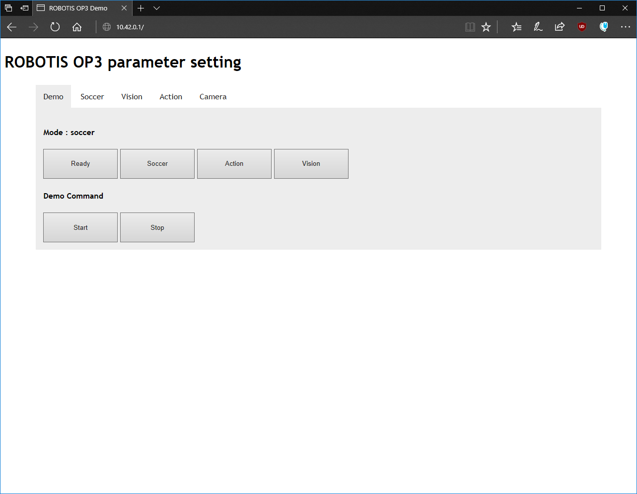
3Camera calibration
If the lighting conditions in the robot's environment are too bright or too dark, you can adjust the camera parameters to optimize the image quality. Additionally, the football color recognition parameters in the automatic kicking mode can also be modified in the camera settings. For detailed instructions, please refer to: 4.19 Use the web-based debugging tool.
![]()
-
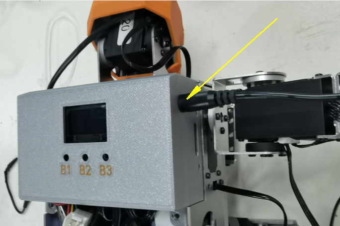
4Charging operation
a. Insert the DC connector of the included 12V dedicated lithium battery charger into the circular charging port on the side of the robot.
![]()
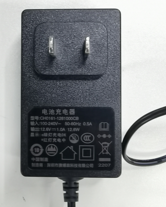
b. Connect the charger's power plug to a 220V AC power outlet.
![]()
c. You can determine the charging status by looking at the LED indicator light on the charger:
The indicator light turns green: this means the battery is fully charged.
The indicator light turns green: this means the battery is fully charged.d. After the indicator light turns green, first unplug the power cord, then disconnect the DC connector.
-
5Important Safety Instructions
a. Do not mix chargers: Please use the official 12V dedicated lithium battery charger. Using a non-official charger may damage the robot's internal circuitry.
b. Do not charge while powered on: Do not charge the robot while it is powered on and operating.
c. Long-term storage and maintenance: Lithium batteries slowly self-discharge when not in use for extended periods.
Please fully charge the robot at least once every three months
-
6Macro-level layered architecture
The SamuRoid robot runs on Ubuntu 20.04, with the ROS environment (ROS Noetic) installed on top of the Ubuntu system. All of the robot's functional packages are developed and run as ROS packages. The following is a diagram of the robot's software architecture:

Macro-level layered architecture -
7Core Component Analysis
In this robotics project, all functionalities are developed as functional modules and packaged as independent ROS packages. For example: custom action group module, head rotation module, sensor data module, etc.
Each module has its own independent algorithm, and the `process` method within each module calculates the corresponding servo angles required to implement that module's functionality. The robot includes the following functional modules:The ROS packages containing the functional modules of the robot are located in the ROBOTIS-OP3 package within the project.

ROBOTIS-OP3 At the same time, in this robot project architecture, the servo motor (Dynamixel) is the smallest execution unit, and each servo motor can be individually bound to a specific functional module. For example, when a head-turning motion is required, the two servo motors in the head need to be bound to the HeadControlModule module.
Module Name Function Description ROS package name ActionModule Execute preset action groups op3_action_module Master Uri Control head rotation op3_head_control_module WalkingModule Control robot walking op3_walking_module BaseModule Basic posture control op3_base_module DirectControlModule Direct control mode op3_direct_control_module OnlineWalkingModule Online walking control op3_online_walking_module -
8Robot Application Manager (robot_manager)
As can be seen from the robot's software architecture diagram, the outermost layer of the robot is the `robot_manager` ROS package. This package is primarily used to manage the various configuration parameters of the SamuRoid robot and load various functional modules, hence it is called the "robot application manager".
Its main function is to load configuration parameters, such as initial servo angles, servo offsets, parameter names to be read, and action file paths. By examining the `op3_manager.launch` file, we can see the path to the configuration file it loads. The content of this file is as follows:<?xml version="1.0" ?> <launch> <param name="gazebo" value="false" type="bool"/> <param name="gazebo_robot_name" value="robotis_op3"/> <param name="offset_file_path" value="$(find op3_tuning_module)/data/offset.yaml"/> <param name="robot_file_path" value="$(find op3_manager)/config/xrgeek.robot"/> <param name="init_file_path" value="$(find op3_manager)/config/xrgeek_init.yaml"/> <param name="device_name" value="/dev/ttyUSB0"/> <!-- OP3 Manager --> <node pkg="op3_manager" type="op3_manager" name="op3_manager" output="screen"> <param name="angle_unit" value="30" /> </node> <!-- OP3 Localization --> <node pkg="op3_localization" type="op3_localization" name="op3_localization" output="screen"/> </launch>Summary of the various configuration file paths:
(1) Offset compensation values for each joint angle: op3_tuning_module/data/offset.yaml
(2) Hardware configuration parameters for each joint and sensor expansion board: op3_manager/config/xrgeek.robot
(3) Configuration items for the attribute value ranges of each joint servo: op3_manager/config/xrgeek_init.yaml
-
9Core Controller and Data Processing Flow
The core of the entire robot architecture is the ROS package of the Framework middleware, whose kernel is responsible for directly interacting with the underlying servos and sensors.
Its code is located at ROBOTIS-Framework/robotis_controller/src/robotis_controller/robotis_controller.cpp.
Module Loading: The top-level robot_manager, upon startup, dynamically registers all functional modules (such as WalkingModule, HeadControlModule, etc.) into the core system by calling the addMotionModule() method of the robotis_controller. controller->addMotionModule((MotionModule *)ActionModule::getInstance());controller->addMotionModule((MotionModule *)BaseModule::getInstance()); controller->addMotionModule((MotionModule *)HeadControlModule::getInstance()); controller->addMotionModule((MotionModule *)WalkingModule::getInstance()); controller->addMotionModule((MotionModule *)DirectControlModule::getInstance()); controller->addMotionModule((MotionModule *)OnlineWalkingModule::getInstance()); controller->addMotionModule((MotionModule *)TuningModule::getInstance());
Control Loop Mechanism: A loop thread is established within the robotis_controller. The core function of this thread is also the `process` method. In each loop cycle, this `process` method iterates through all modules loaded into the kernel and executes each module's own `process()` method. After each module completes its calculations, it stores the results (i.e., the target angle values for the specified joint_name) in its `result_` member. Finally, the robotis_controller kernel collects these angle values and sends them to the corresponding servo motors via the DynamixelSDK, causing them to rotate to the specified angles, thus achieving precise control of the robot's joints.
Example: Controlling the robot's head rotation
In the head control function, the HeadControlModule is bound to the horizontal rotation servo head_pan (ID: 19) and the vertical rotation servo head_tilt (ID: 20). The IDs of these two servos can be found in the ROBOTIS-OP3\op3_manager\config\OP3.robot configuration file of the project.
The HeadControlModule is called in each process() loop of the robotis_controller. This module calculates the target angles for servos 19 and 20 to rotate the head to the target position and returns these angle values to the robotis_controller. Finally, the robotis_controller uses the DynamixelSDK interface to send these angles to the head servos, as shown in the following diagram:
diagram -
10Servo motor distribution
The SamuRoid robot integrates a total of 22 high-performance servo motors, whose distribution, names, and functions are shown in the table below:
As picture:

SamuRoid Parts Number Servo name Function description Head 2 head_pan Head horizontal rotation head_tilt Head vertical pitch Arms 8 r_sho_pitch / l_sho_pitch Right/Left shoulder forward/backward swing r_sho_roll / l_sho_roll Right/Left shoulder lateral elevation r_el / l_el Right/Left elbow joint flexion r_palm / l_palm Right/Left hand opening/closing Legs 12 r_hip_yaw / l_hip_yaw Right/Left hip joint horizontal rotation r_hip_roll / l_hip_roll Right/Left hip joint lateral swing r_hip_pitch / l_hip_pitch Right/Left hip joint forward/backward swing r_knee / l_knee Right/Left knee joint flexion r_ank_pitch / l_ank_pitch Right/Left ankle joint forward/backward swing r_ank_roll / l_ank_roll Right/Left ankle joint lateral swing
SamuRoid: 22-DOF Embodied AI & ROS Humanoid
Open-source bipedal robot powered by Raspberry Pi 4B. Features IK-based gait, 30kg.cm bus servos, and DeepSeek LLM integration for AI resear


Discussions
Become a Hackaday.io Member
Create an account to leave a comment. Already have an account? Log In.