 Arnov Sharma
-
11REST OF GREEBLES ASSEMBLY
![]()
![]()
![]()
![]()
![]()
![]()
![]()
![]()
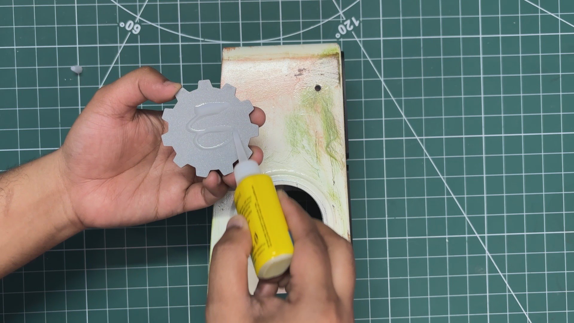
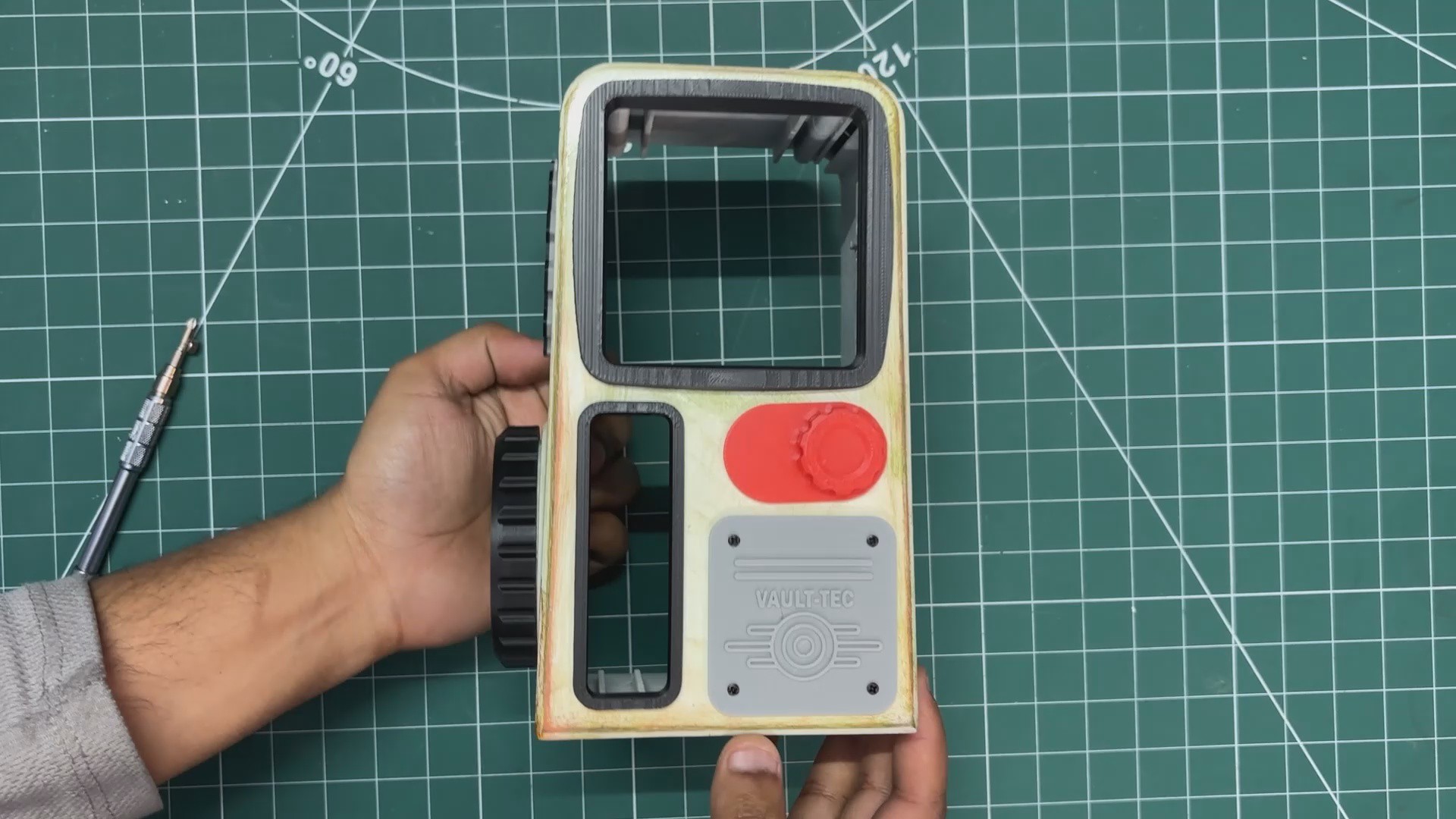
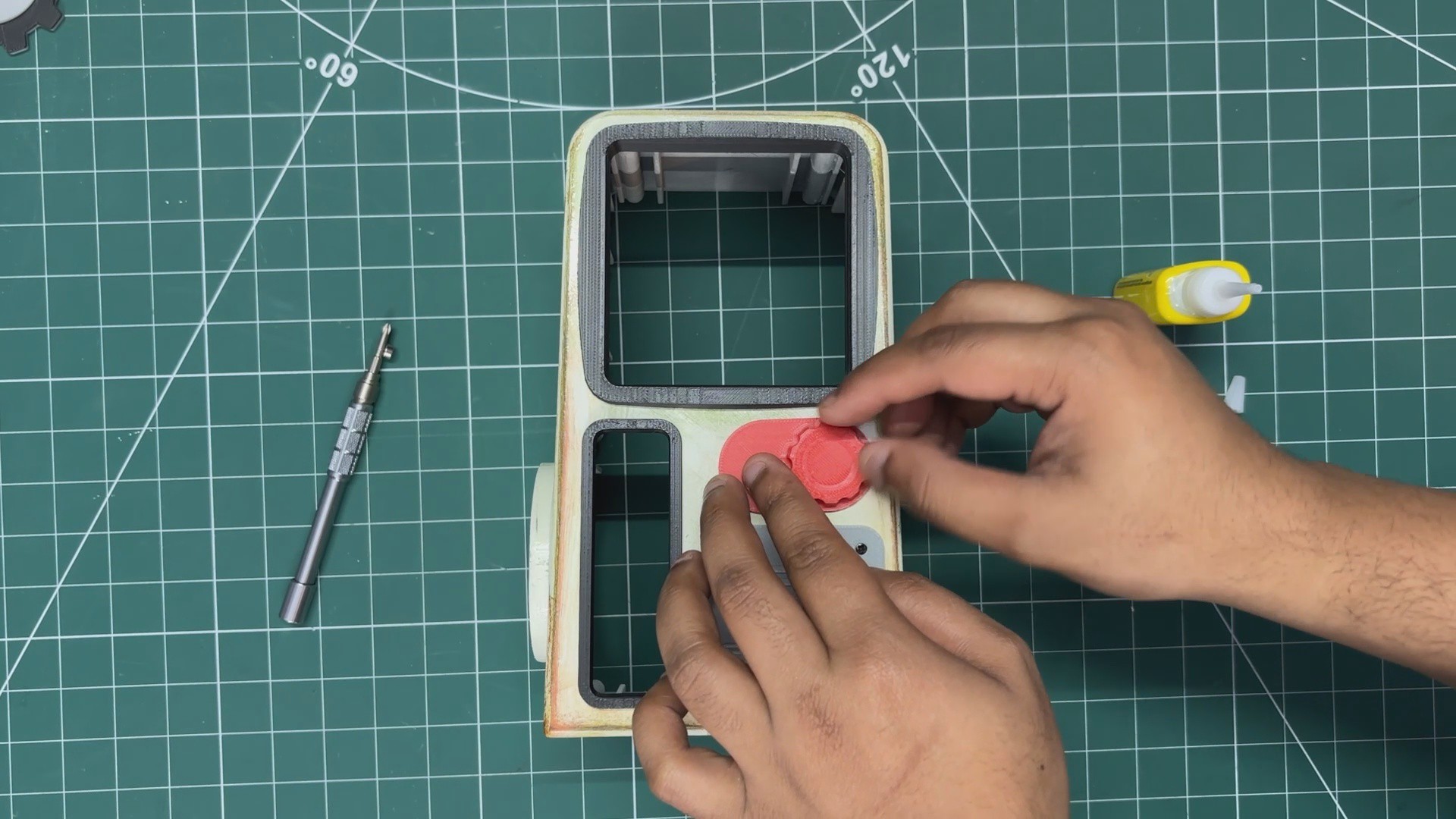
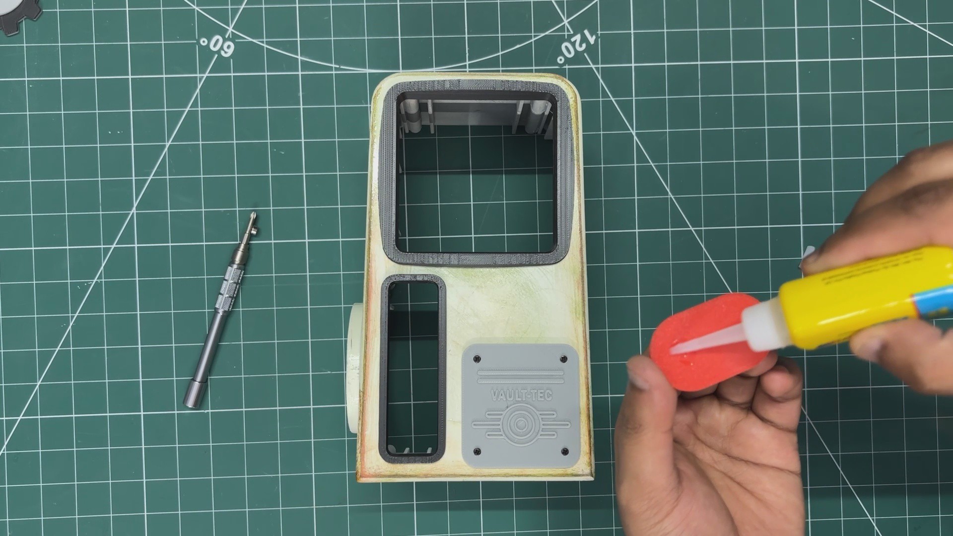
- Superglue is applied to the backside of the front knob part and it is positioned slightly above the Vault-Tec logo.
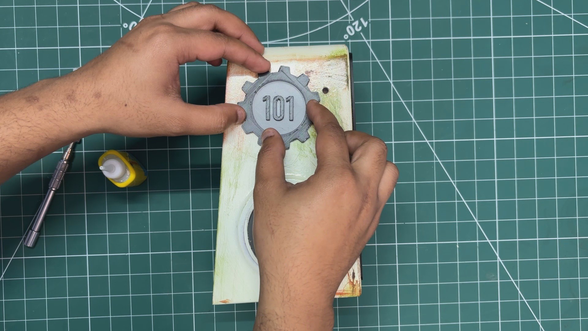
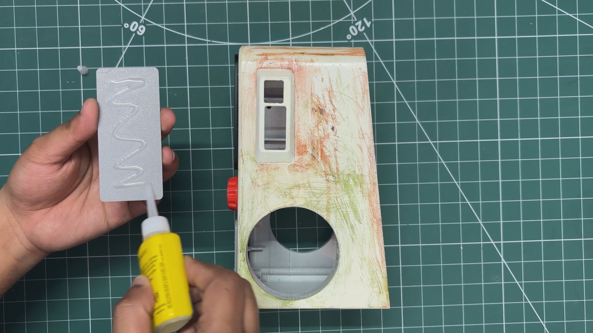
- Similarly, I applied superglue to the back of the Vault 101 part and positioned it on the left side of the main body.
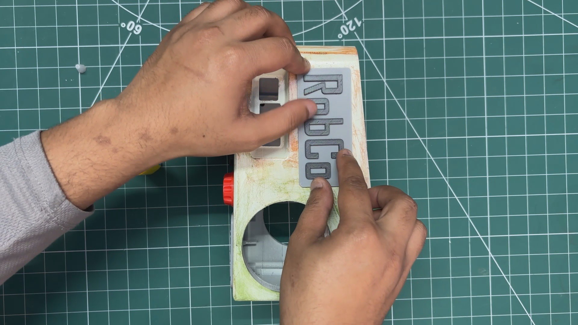
- I then added superglue to the back of the RobCo Industries logo and positioned it on the right side of the main body.
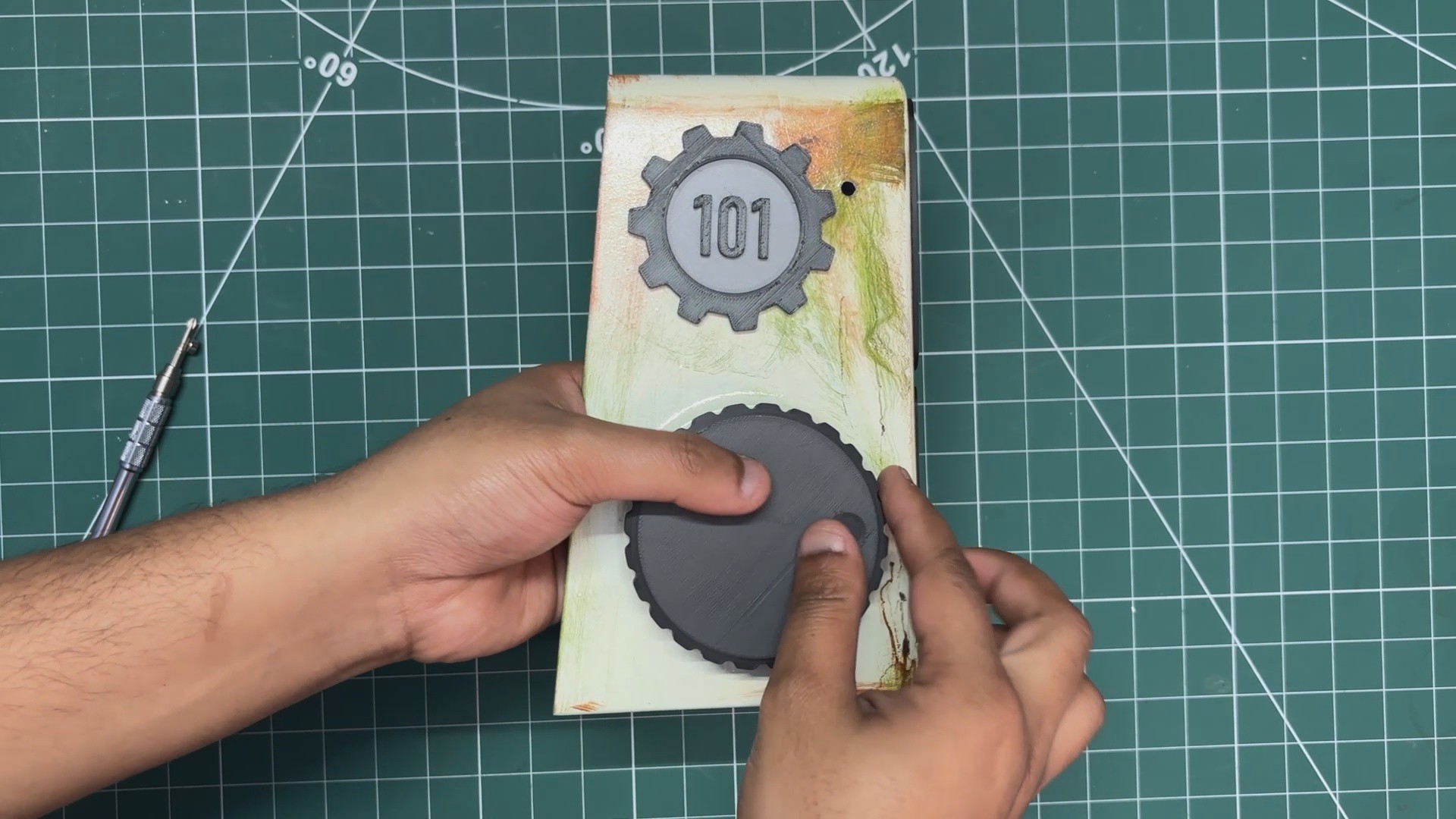
- Finally, the knob is installed on the left side of the main body. This knob was pressure-fitted into place, completing the main body assembly process.
-
12SGP40 TVOC SETUP, CODE & TEST RUN
![]()
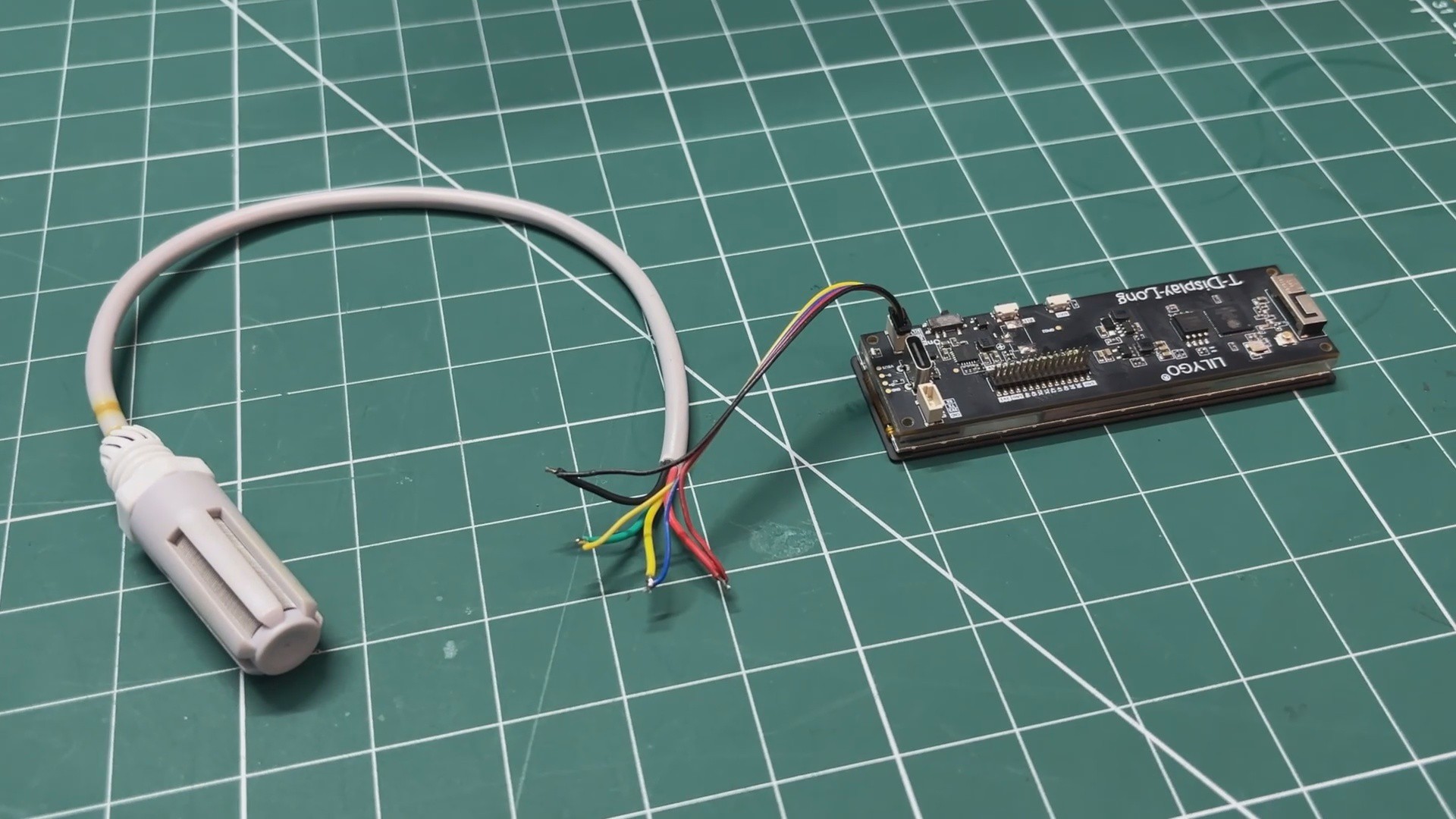
For the air quality meter setup, I connected the I2C pins of the SGP40 sensor directly to the I2C connector of the TTGO T-Display board. This allowed the ESP32 to communicate with the sensor using the standard SDA and SCL lines.
Once the hardware connections were completed, I uploaded the main sketch to the TTGO T-Display board.
Below is the main code used for this setup.
#include <Arduino.h>
#include <Wire.h>
#include "AXS15231B.h"
#include "pins_config.h"
#include <Adafruit_SGP40.h>
#include "fontFull.h"
/* ================= DISPLAY ================= */
#define SCREEN_W 640
#define SCREEN_H 180
uint16_t frameBuffer[SCREEN_W * SCREEN_H];
/* ================= COLORS ================= */
#define TERMINAL_YELLOW  0x07FF
#define BLACK            0x0000
/* ================= SGP40 ================= */
Adafruit_SGP40 sgp;
uint16_t vocRaw = 0;
uint16_t vocSmooth = 0;
uint16_t vocDisplay = 0;
/* ================= STATE ================= */
bool startupAnim = true;
int animLevel = 10;
int animDir = -1;
unsigned long animStart = 0;
unsigned long lastAnimStep = 0;
/* ================= ROTATED PUSH ================= */
void lcd_PushColors_rotated(uint16_t w, uint16_t h, uint16_t *data)
{
static uint16_t line[SCREEN_H];
for (int col = w - 1; col >= 0; col--) {
lcd_address_set(0, (w - 1) - col, h - 1, (w - 1) - col);
for (int row = 0; row < h; row++) {
line[row] = data[row * w + col];
}
lcd_PushColors(line, h);
}
}
/* ================= FRAMEBUFFER ================= */
void clearFB() { memset(frameBuffer, 0, sizeof(frameBuffer)); }
void fillRectFB(int x, int y, int w, int h, uint16_t c)
{
for (int j = 0; j < h; j++) {
uint16_t *row = &frameBuffer[(y + j) * SCREEN_W + x];
for (int i = 0; i < w; i++) row[i] = c;
}
}
/* ================= FONT ================= */
void drawCharRot90CCW_Fixed(int x, int y, char c, uint16_t col, uint8_t scale)
{
const uint8_t* bmp = fontFull_getBitmap(c);
for (int cx = 0; cx < 5; cx++) {
uint8_t bits = pgm_read_byte(&bmp[cx]);
for (int cy = 0; cy < 7; cy++) {
if (bits & 0x01) {
fillRectFB(x + (6 - cy) * scale, y + cx * scale, scale, scale, col);
}
bits >>= 1;
}
}
}
void drawTextVertical(int x, int y, const char* txt, uint16_t col, uint8_t scale)
{
while (*txt) {
drawCharRot90CCW_Fixed(x, y, *txt, col, scale);
y += (5 * scale) + scale;
txt++;
}
}
/* ================= UI LAYOUT ================= */
#define BTN_PADDING 12
#define BTN_GAP     10
#define BTN_Y       BTN_PADDING
#define BTN_H       (SCREEN_H - BTN_PADDING * 2)
#define BTN_W       ((SCREEN_W - BTN_PADDING * 2 - BTN_GAP * 3) / 4)
/* ================= BARS ================= */
#define BAR_COUNT 10
uint8_t vocToBars(uint16_t voc)
{
if (voc <= 100) return 2;
if (voc <= 200) return 4;
if (voc <= 400) return 6;
if (voc <= 600) return 8;
return 10;
}
void drawBars(uint8_t level)
{
int areaX = BTN_PADDING;
int areaY = BTN_Y;
int areaW = (BTN_W * 3) + (BTN_GAP * 2);
int areaH = BTN_H;
fillRectFB(areaX, areaY, areaW, areaH, BLACK);
int gap = 5;
int barW = (areaW - (BAR_COUNT + 1) * gap) / BAR_COUNT;
int barH = areaH - 24;
for (int i = 0; i < level; i++) {
int x = areaX + gap + i * (barW + gap);
fillRectFB(x, areaY + 12, barW, barH, TERMINAL_YELLOW);
}
}
/* ================= RADS PANEL ================= */
void drawRADS(uint16_t voc)
{
int panelX = BTN_PADDING + (BTN_W + BTN_GAP) * 3;
int panelY = BTN_Y;
int panelW = BTN_W;
int panelH = BTN_H;
fillRectFB(panelX, panelY, panelW, panelH, BLACK);
int bw = 3;
fillRectFB(panelX, panelY, panelW, bw, TERMINAL_YELLOW);
fillRectFB(panelX, panelY + panelH - bw, panelW, bw, TERMINAL_YELLOW);
fillRectFB(panelX, panelY, bw, panelH, TERMINAL_YELLOW);
fillRectFB(panelX + panelW - bw, panelY, bw, panelH, TERMINAL_YELLOW);
int padTop = 43;
int radsX = panelX + panelW - 38;
int numberX = radsX - 80;
int radY = panelY + padTop;
drawTextVertical(radsX, radY, "RADS", TERMINAL_YELLOW, 3);
int lineX = radsX - 20;
int lineY = panelY + bw + 2;
int lineH = panelH - (bw * 2) - 4;
fillRectFB(lineX, lineY, 2, lineH, TERMINAL_YELLOW);
int numberY = radY + (4 * (5 * 3 + 1)) + 6 - 90;
char buf[8];
snprintf(buf, sizeof(buf), "%u", voc);
drawTextVertical(numberX, numberY, buf, TERMINAL_YELLOW, 6);
}
/* ================= SETUP ================= */
void setup()
{
pinMode(TFT_BL, OUTPUT);
digitalWrite(TFT_BL, HIGH);
Wire.begin(15, 10);
axs15231_init();
sgp.begin();
animStart = millis();
}
/* ================= LOOP ================= */
void loop()
{
clearFB();
// -------- SENSOR STABILIZATION --------
vocRaw = sgp.measureVocIndex();
// Exponential smoothing
vocSmooth = (vocSmooth * 7 + vocRaw) / 8;
// Peak-hold with slow decay
if (vocSmooth > vocDisplay) {
vocDisplay = vocSmooth;
} else if (vocDisplay > 0) {
vocDisplay--;   // slow decay
}
drawRADS(vocDisplay);
if (startupAnim) {
if (millis() - lastAnimStep > 350) {
animLevel += animDir;
if (animLevel <= 1 || animLevel >= BAR_COUNT)
animDir = -animDir;
lastAnimStep = millis();
}
drawBars(animLevel);
if (millis() - animStart > 7000)
startupAnim = false;
} else {
drawBars(vocToBars(vocDisplay));
}
lcd_PushColors_rotated(SCREEN_W, SCREEN_H, frameBuffer);
delay(30);
}
I have added the AXS15231B.h and.cpp files along with the fontFull.h file, which you need to put in the same folder as the.ino file.
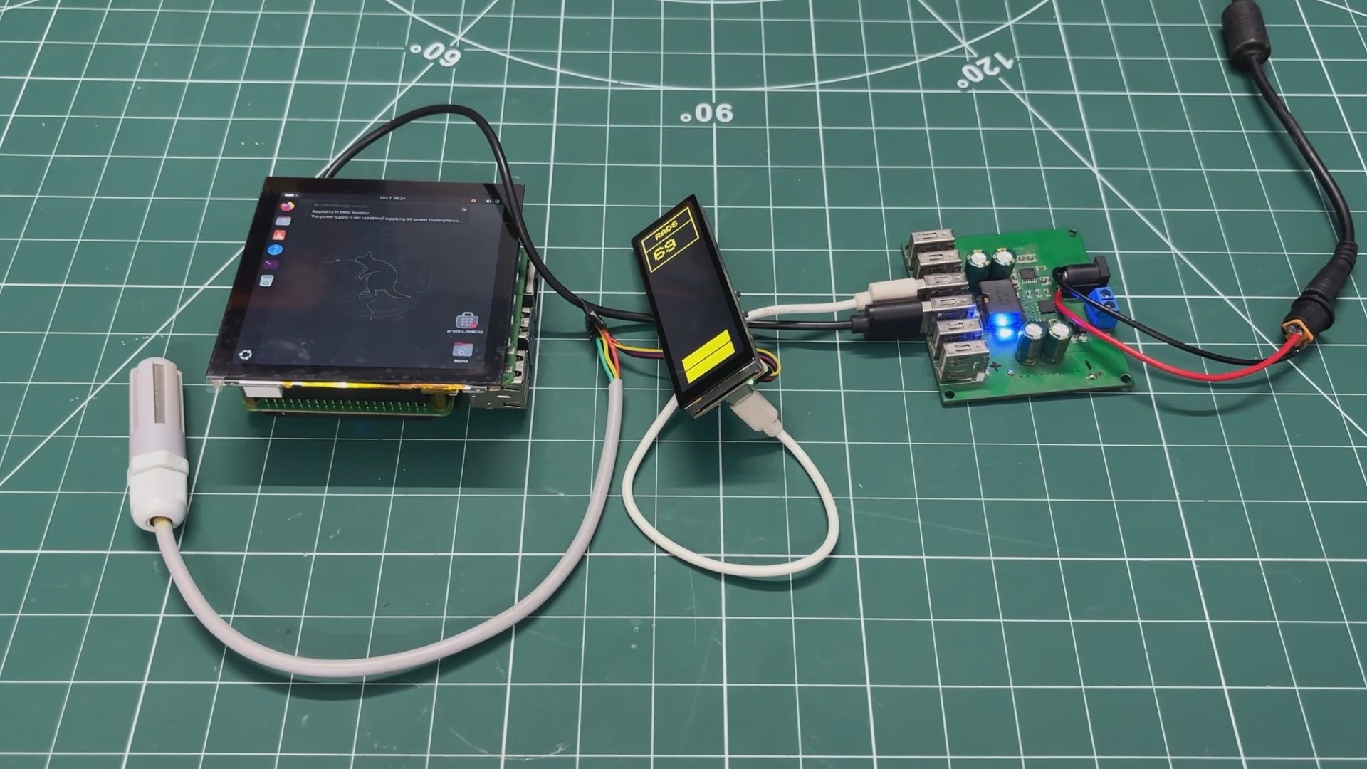
For the demo run, I used an incense stick to increase the VOC levels through smoke release. As the VOC concentration rises, the displayed readings increase, and the number of bars on the screen increases accordingly.
-
13DC STEP DOWN MODULE
![]()
![]()
![]()
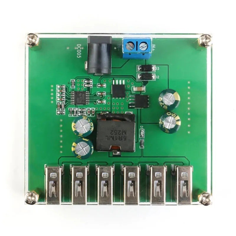
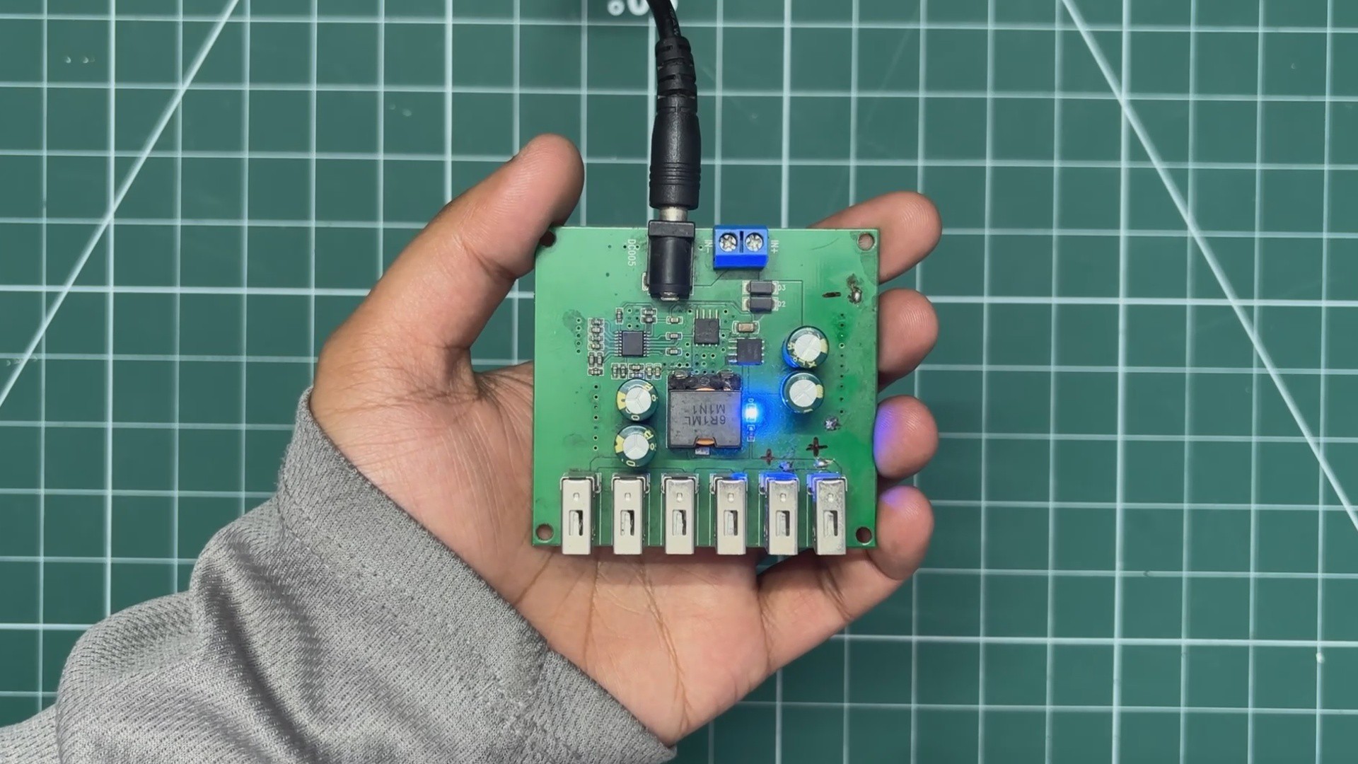
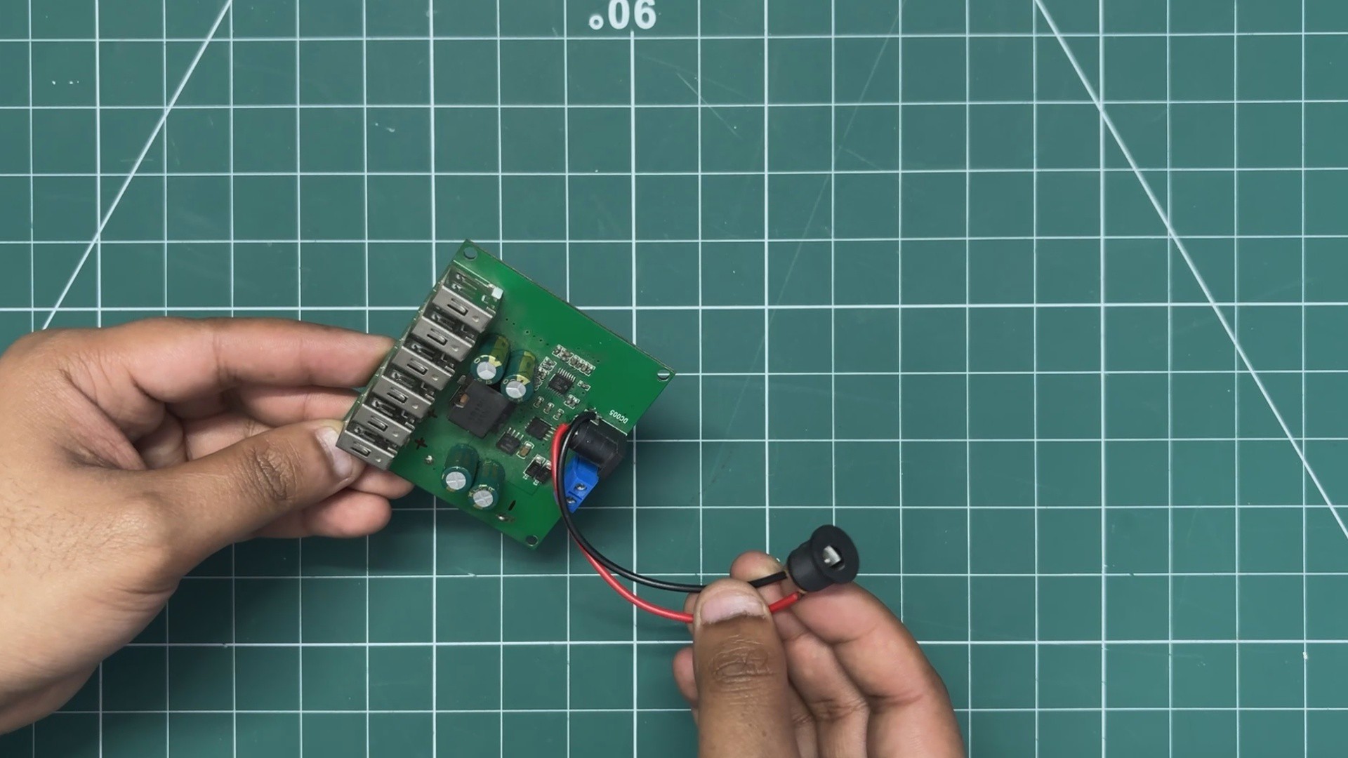
To power the Raspberry Pi, display, and ESP32 from a single supply, we used a high-current DC buck converter module.
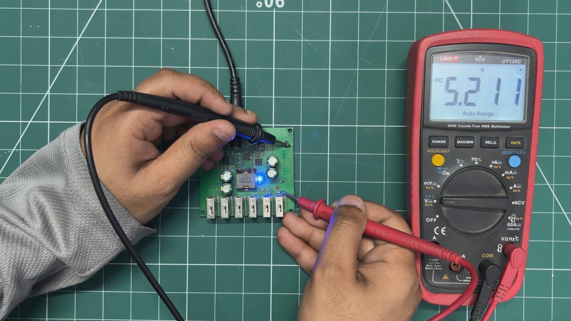
Specifically, we chose a 6-USB Output DC Step-Down Module capable of converting 8V–40V DC input down to a regulated 5V output at up to 8A.
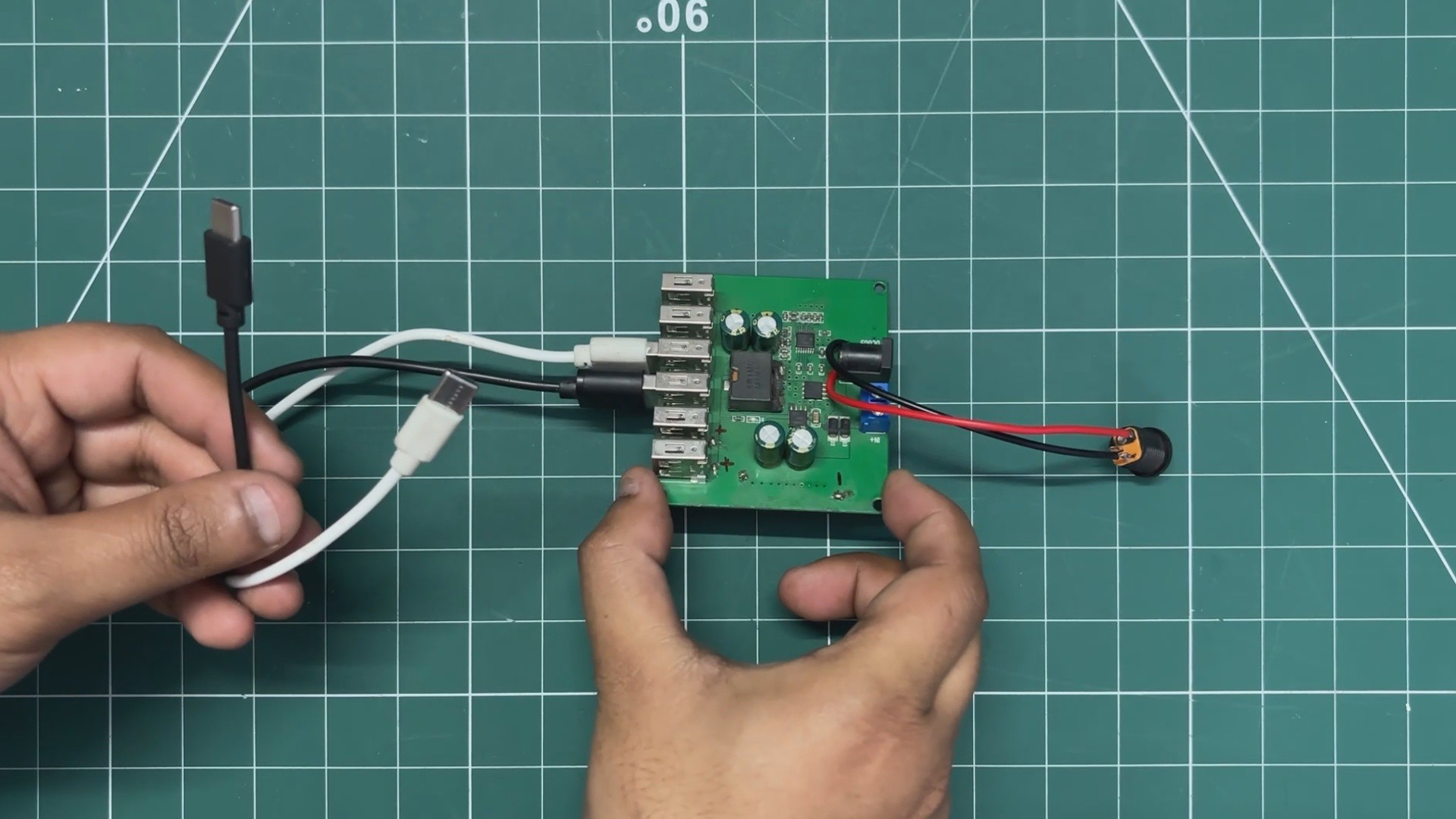
The module accepts power through a DC barrel jack, allowing the use of a wide range of adapters, including 12V, 24V, or even 36V supplies. This makes the power system flexible and easy to adapt to different setups.
The regulated 5V output is distributed through six onboard USB ports, enabling multiple devices to be powered simultaneously without the need for separate regulators.
-
14POWER SOURCE ASSEMBLY
![]()
![]()
![]()
For power, I wanted to use a 12 V 4A power adapter with a DC barrel jack male connector.
- To connect it to the DC step-down module, I soldered a DC barrel jack female connector, wiring its positive and negative terminals to the input ports of the DC step-down module.
- For power distribution between the Raspberry Pi–display setup and the TTGO T-Display board, I used two short USB Type-C cables, which power both setups reliably without any soldering.
While I could have soldered these connections directly, using Type-C cables was simply quicker and more convenient.
-
15MAIN DISPLAY ASSEMBLY
![]()
![]()
![]()
![]()
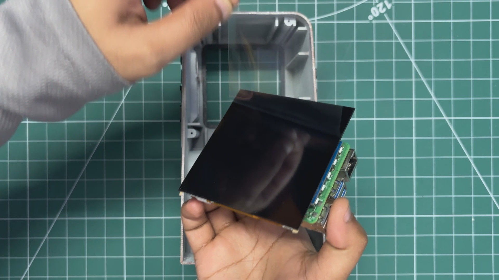
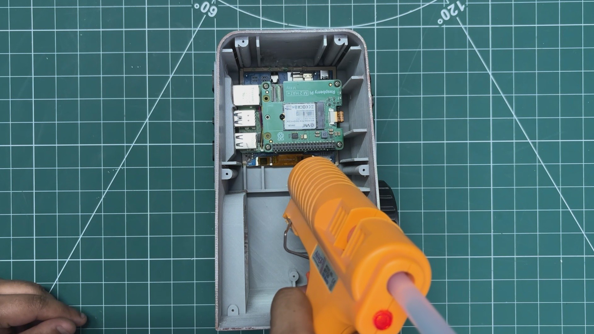
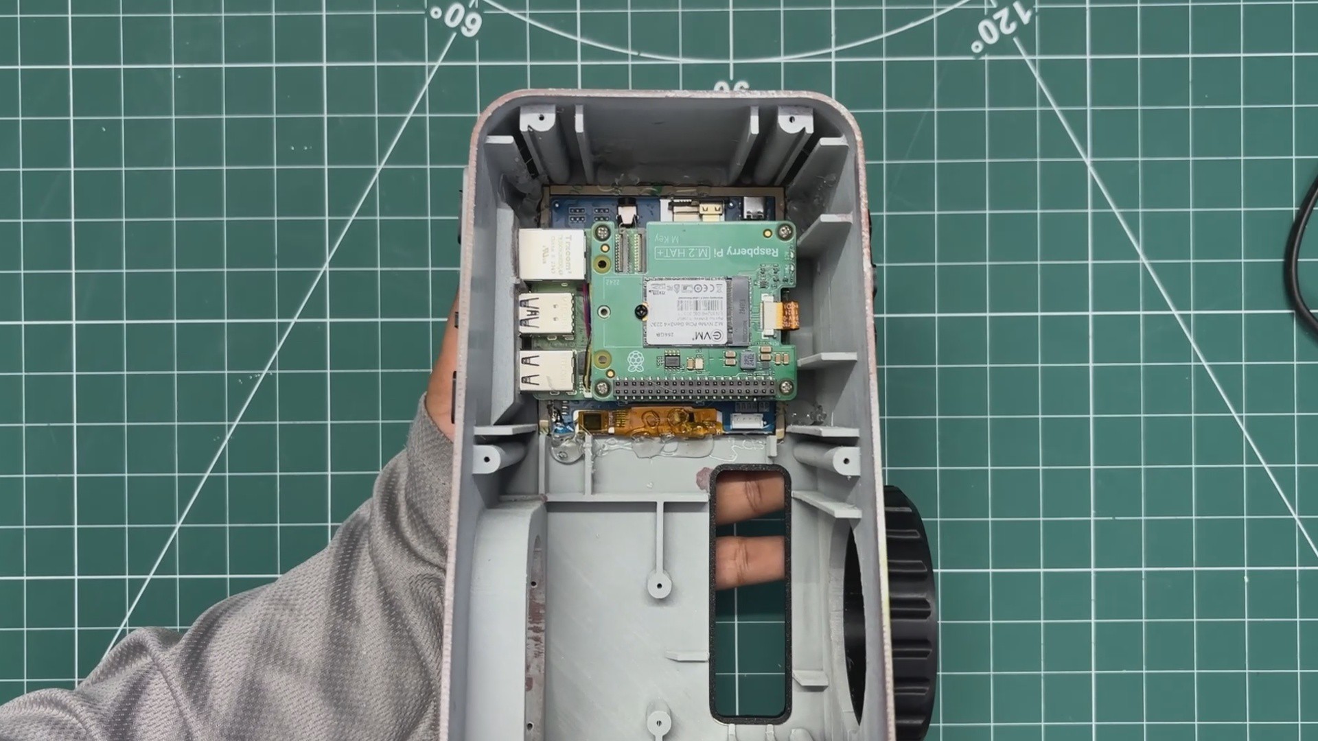
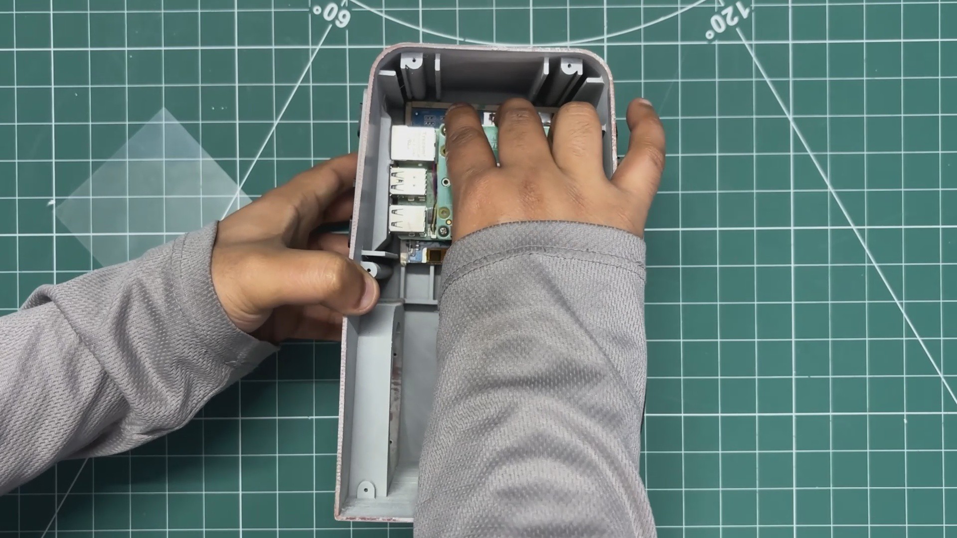
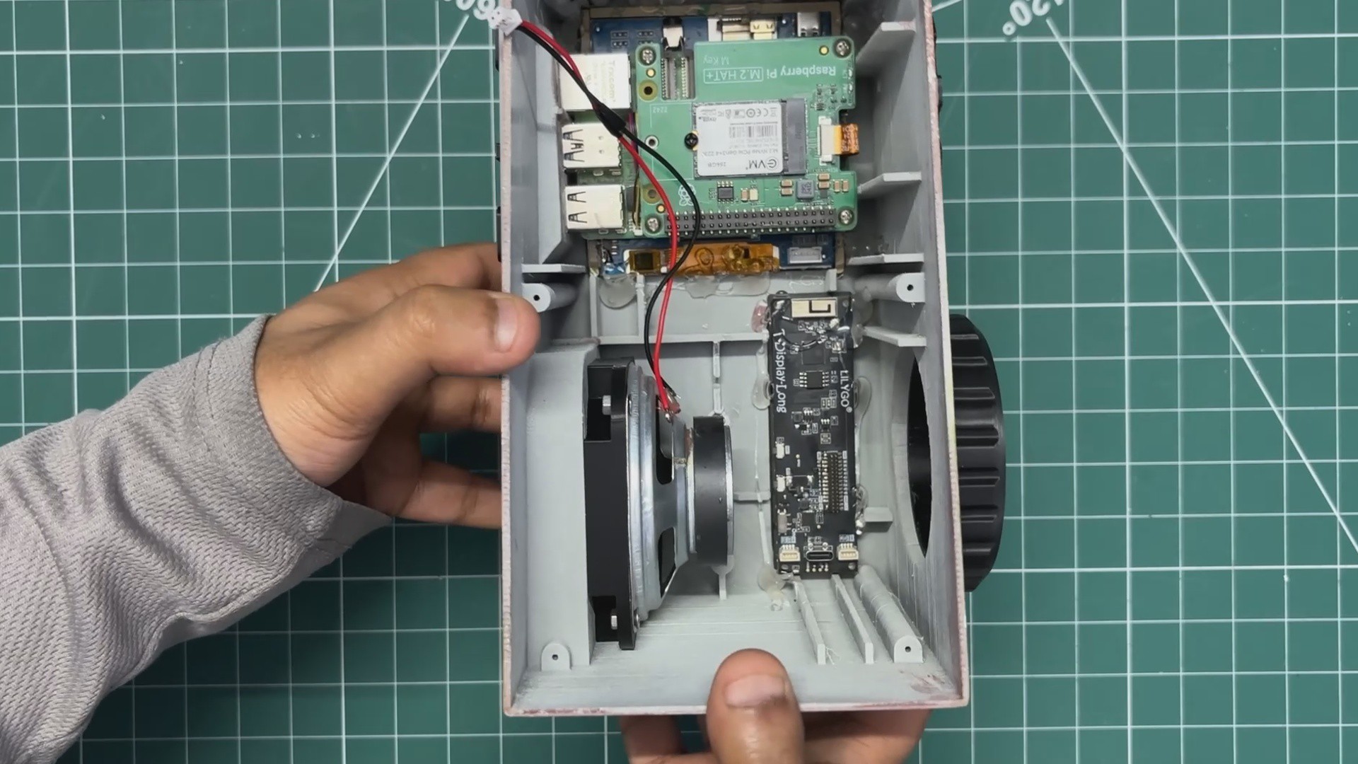
The protective covering from the main display was removed, and the whole Raspberry Pi display setup was then slid down into its position.
Using a small amount of hot glue, the Raspberry Pi display setup was secured in place.
-
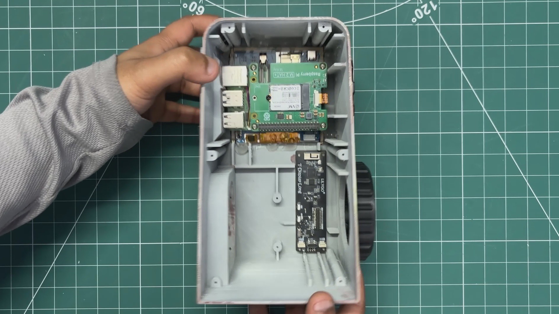
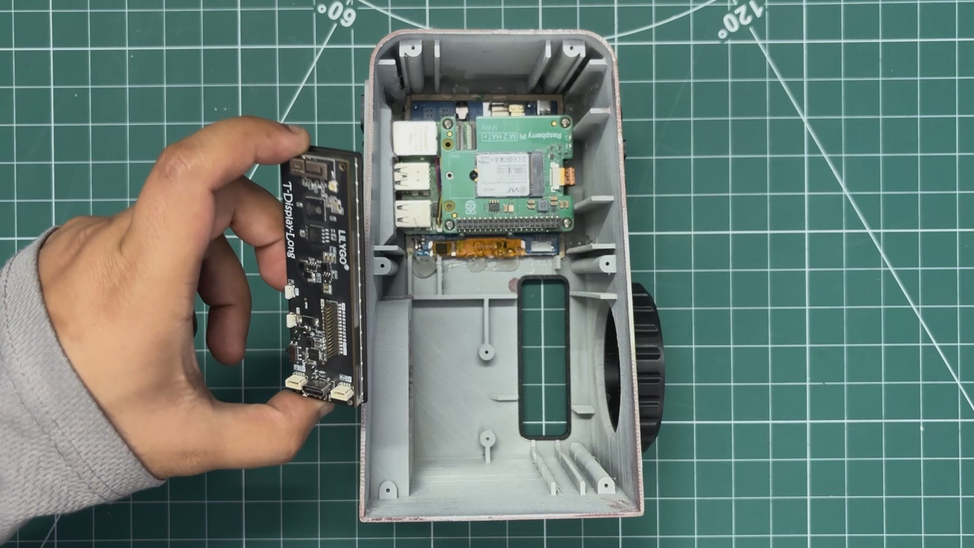
16SECONDARY DISPLAY ASSEMBLY
![]()
![]()
![]()
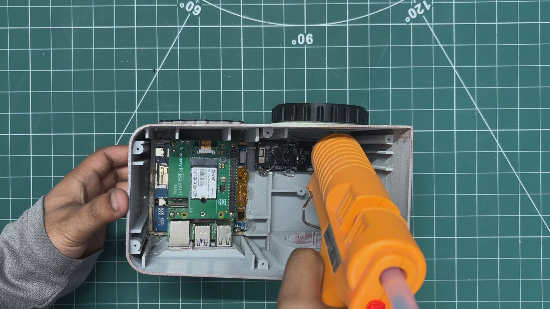
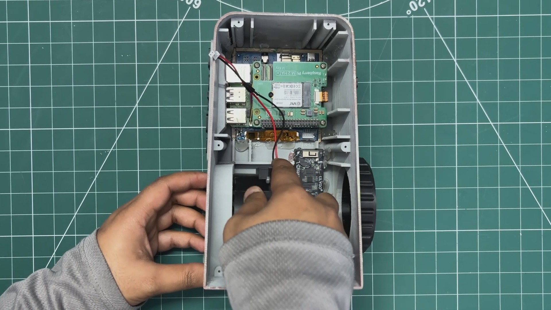
Next, the TTGO T- DISPLAY Board was positioned in its mounting position in the correct orientation, hotglue was used to secure it in its place
-
17SPEAKER ASSEMBLY
![]()
![]()
![]()
![]()
![]()
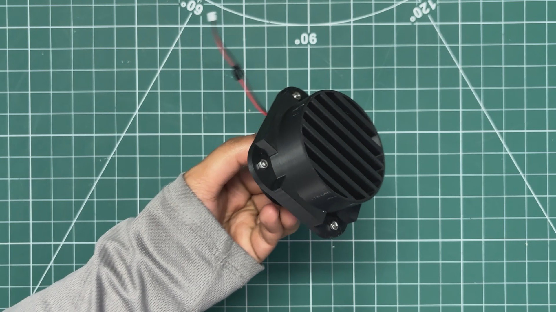
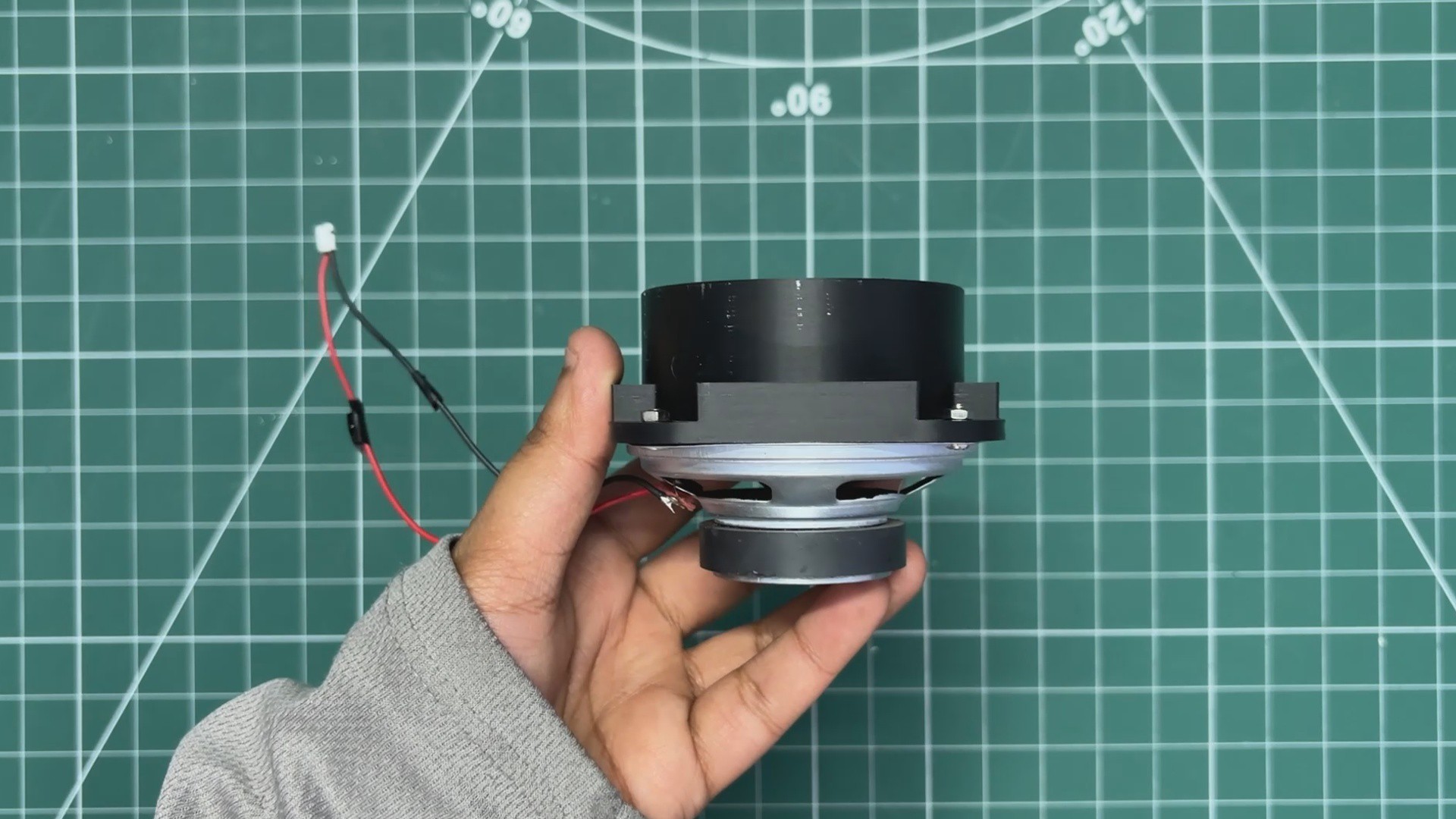
- For the Speaker Assembly, I used M2 nuts and bolts to secure the speaker grill to the 4-ohm speaker mounting holes.
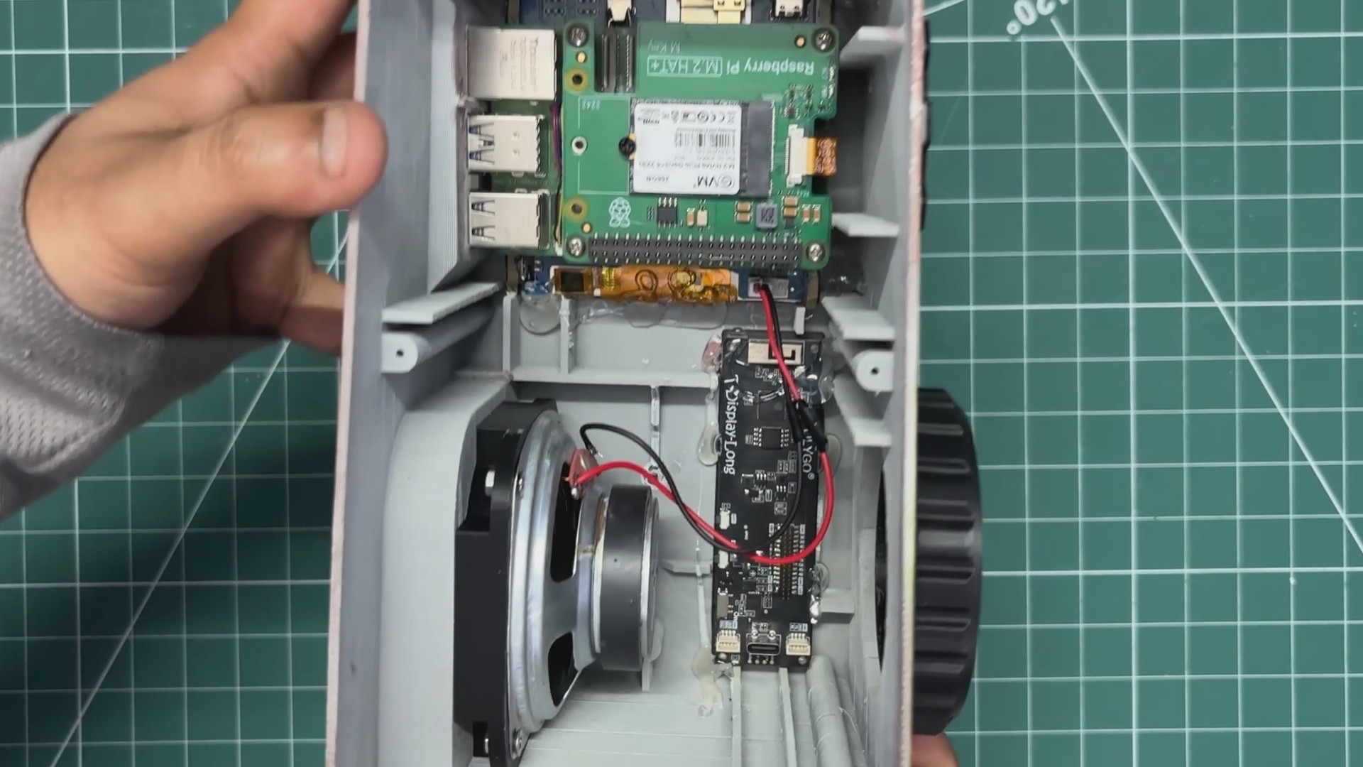
- The entire speaker grill assembly was then slid into its position from the inside of the main body, where it is pressure-fitted in place.
- Finally, I connected the speaker’s CON2 connector to the audio connector on the Waveshare display.
-
18LID ASSEMBLY- SENSOR & DC JACK
![]()
![]()
![]()
![]()
![]()
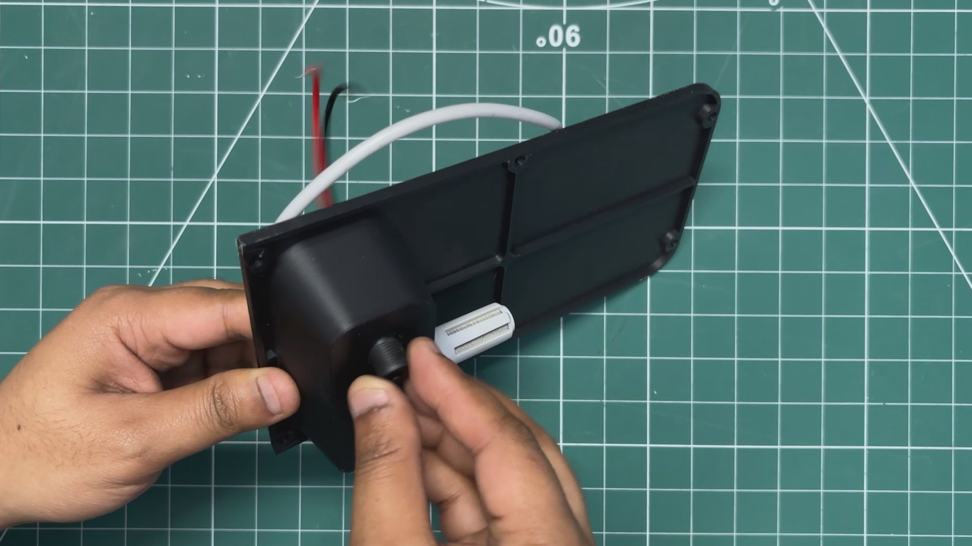
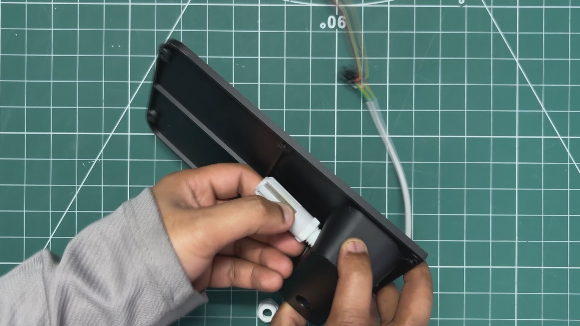
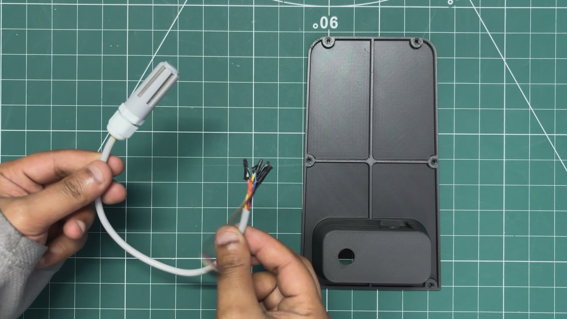
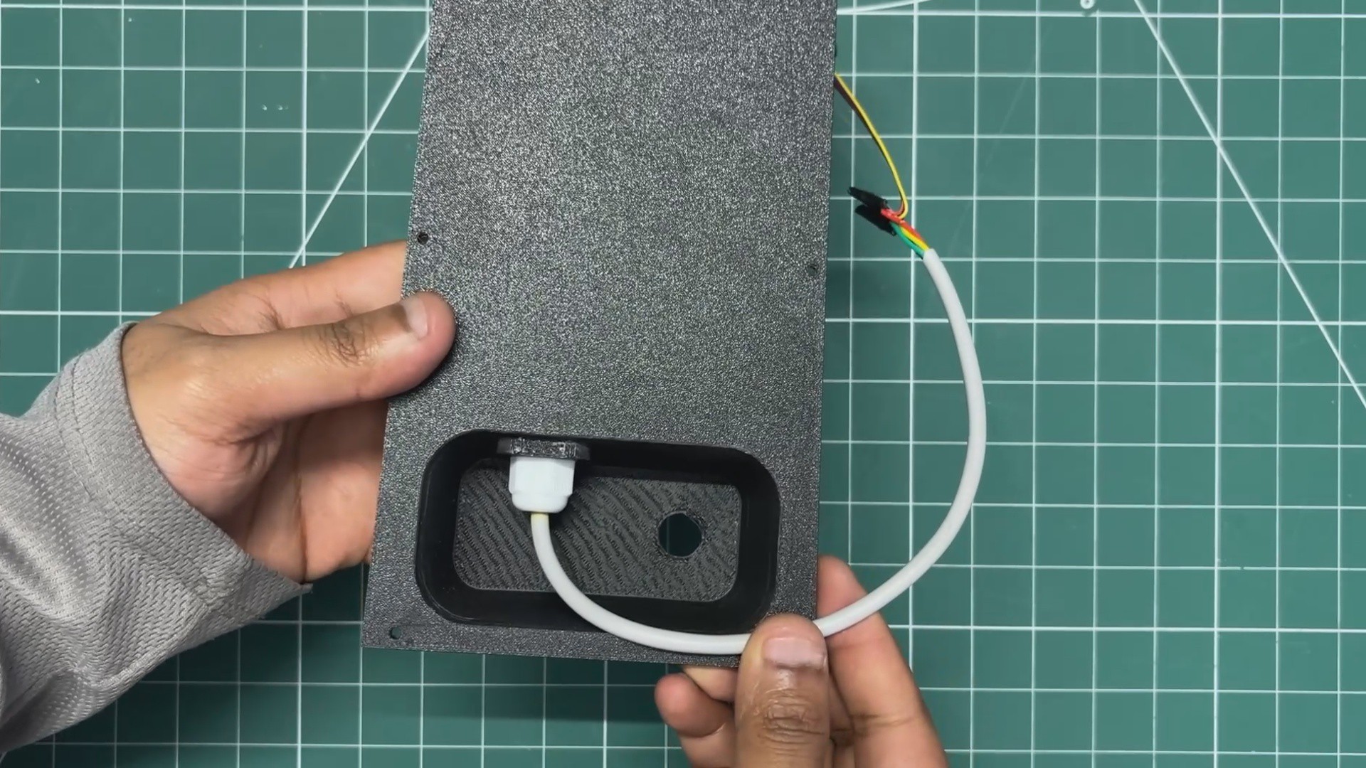
- The lid assembly starts by first installing the SGP40 sensor.
- The PG7 connector nut was unscrewed, the sensor wire was passed through the hole in the lid, and the nut was then tightened to secure the SGP40 in place.
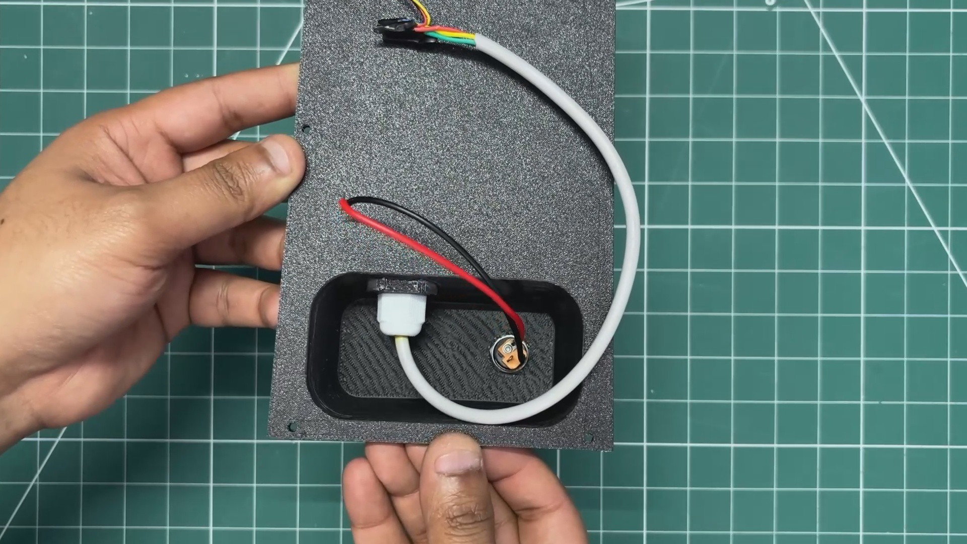
- Next, the DC barrel jack was inserted into its mounting position, and the retaining nut was tightened to firmly secure it.
-
19LID ASSEMBLY- DC STEP DOWN MODULE
![]()
![]()
![]()
![]()
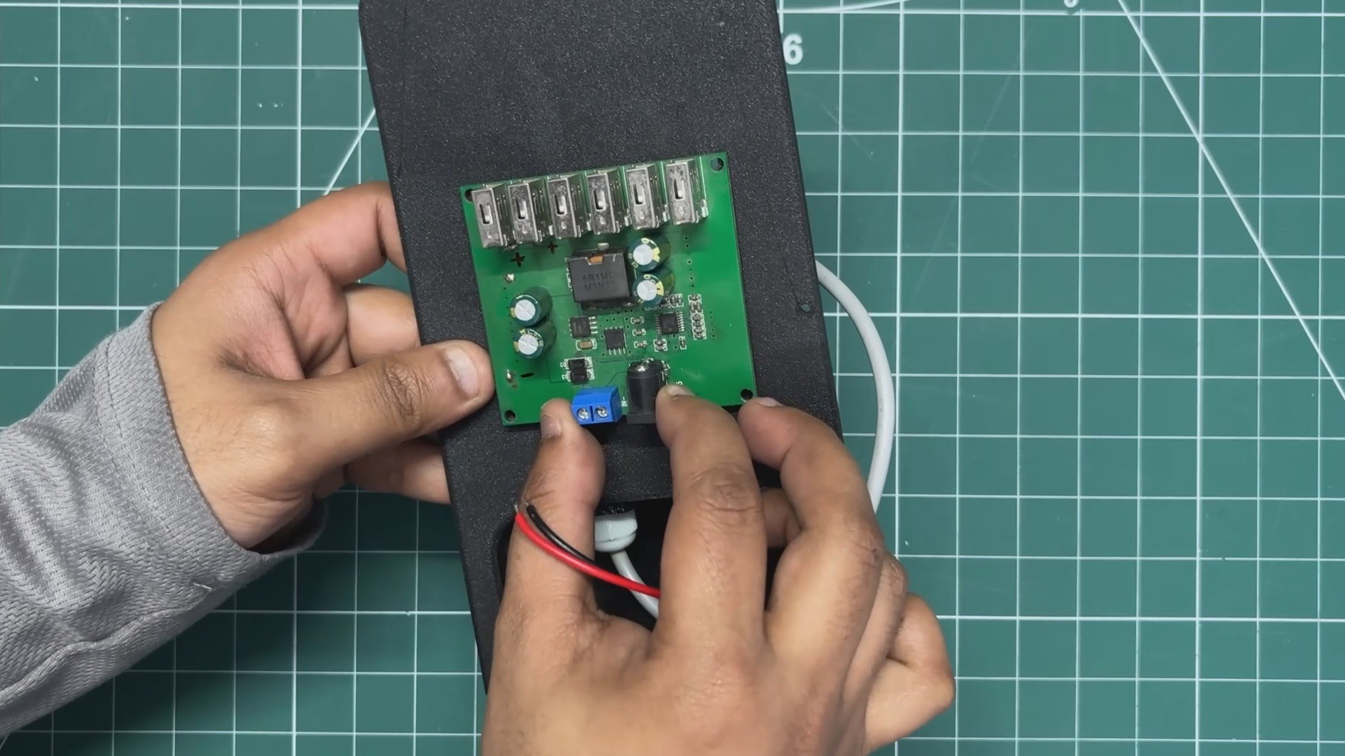
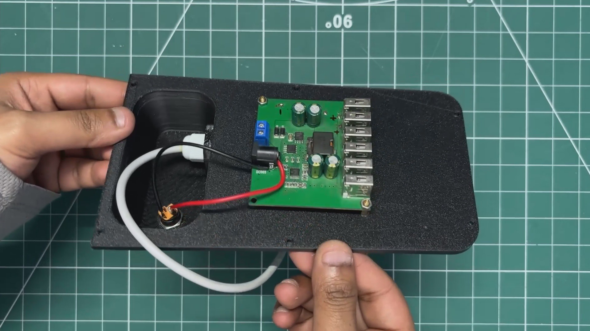
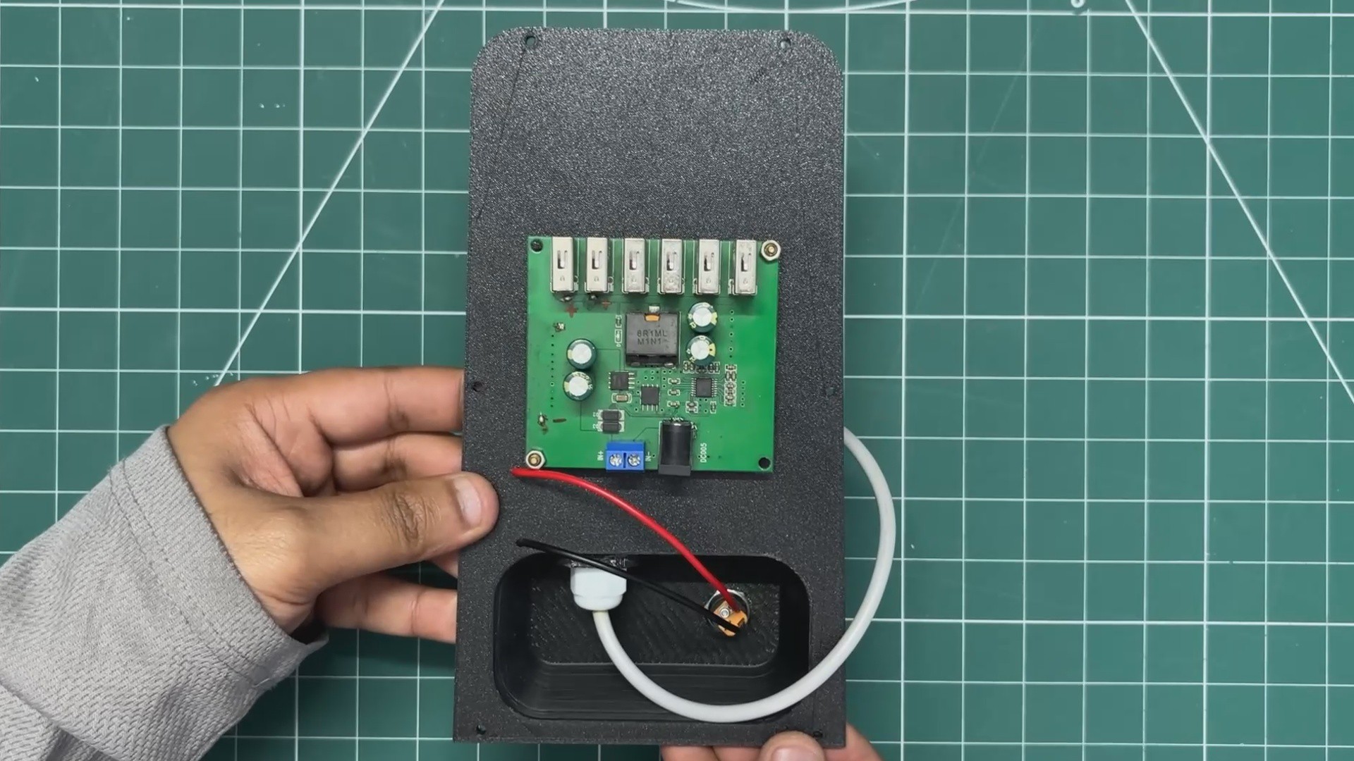
- The DC step-down module is placed over its mounting position and then fastened in place using two M2 PCB standoffs and M2 bolts.
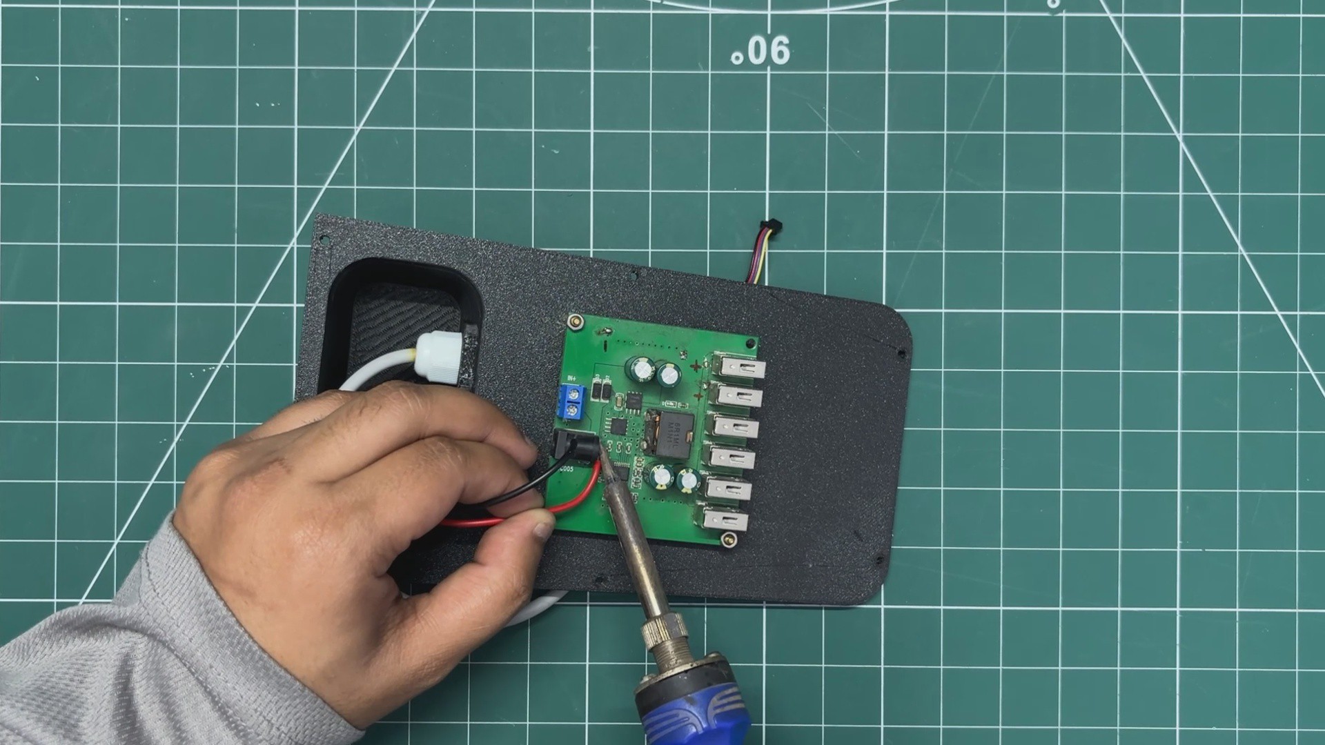
- After that, the DC barrel connector’s positive and negative wires are re-soldered to the input terminals of the DC step-down module.
With this, the lid assembly process is complete, and we can now begin the final assembly process.
-
20FINAL ASSEMBLY PROCESS
![]()
![]()
![]()
![]()
![]()
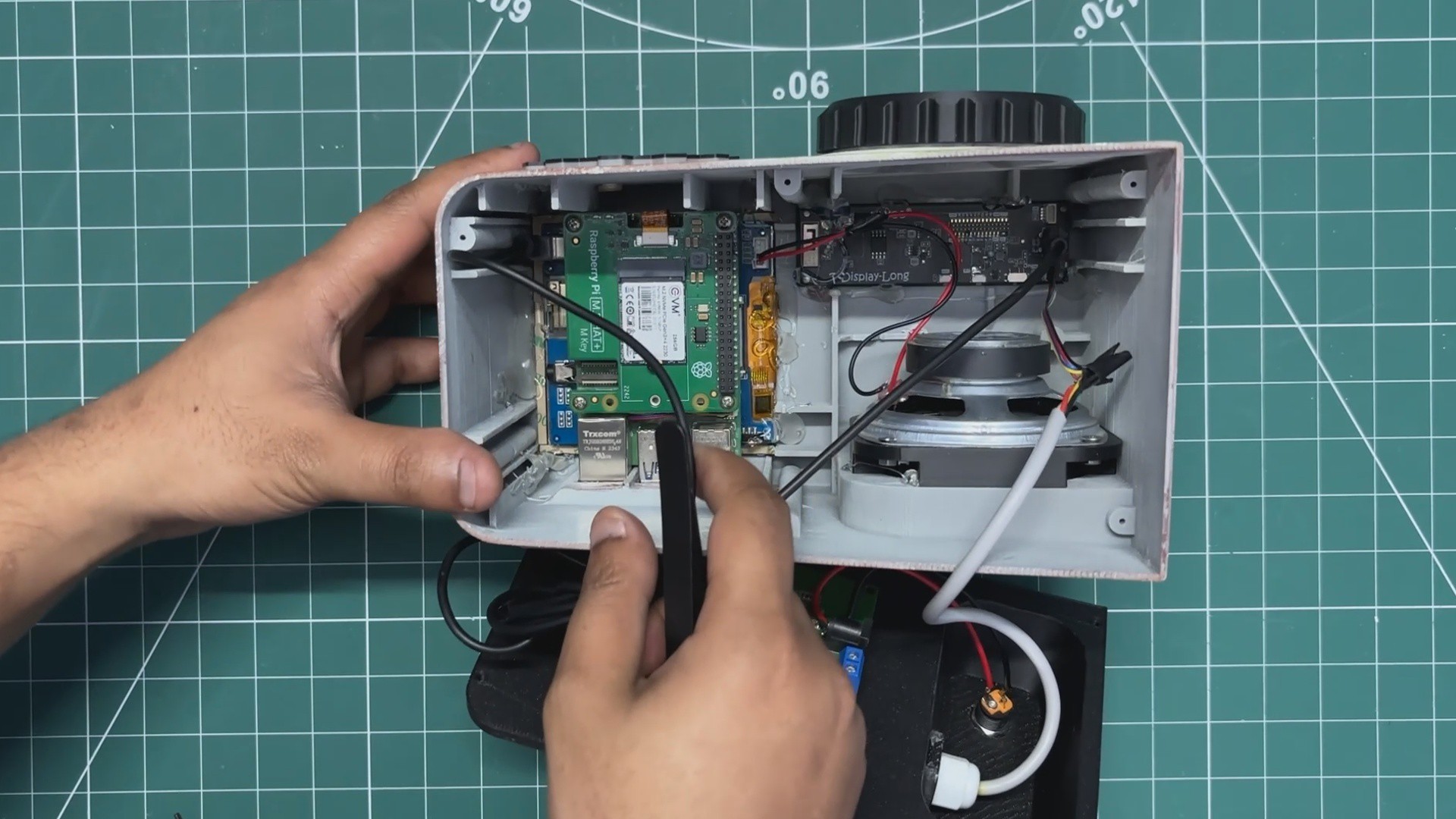
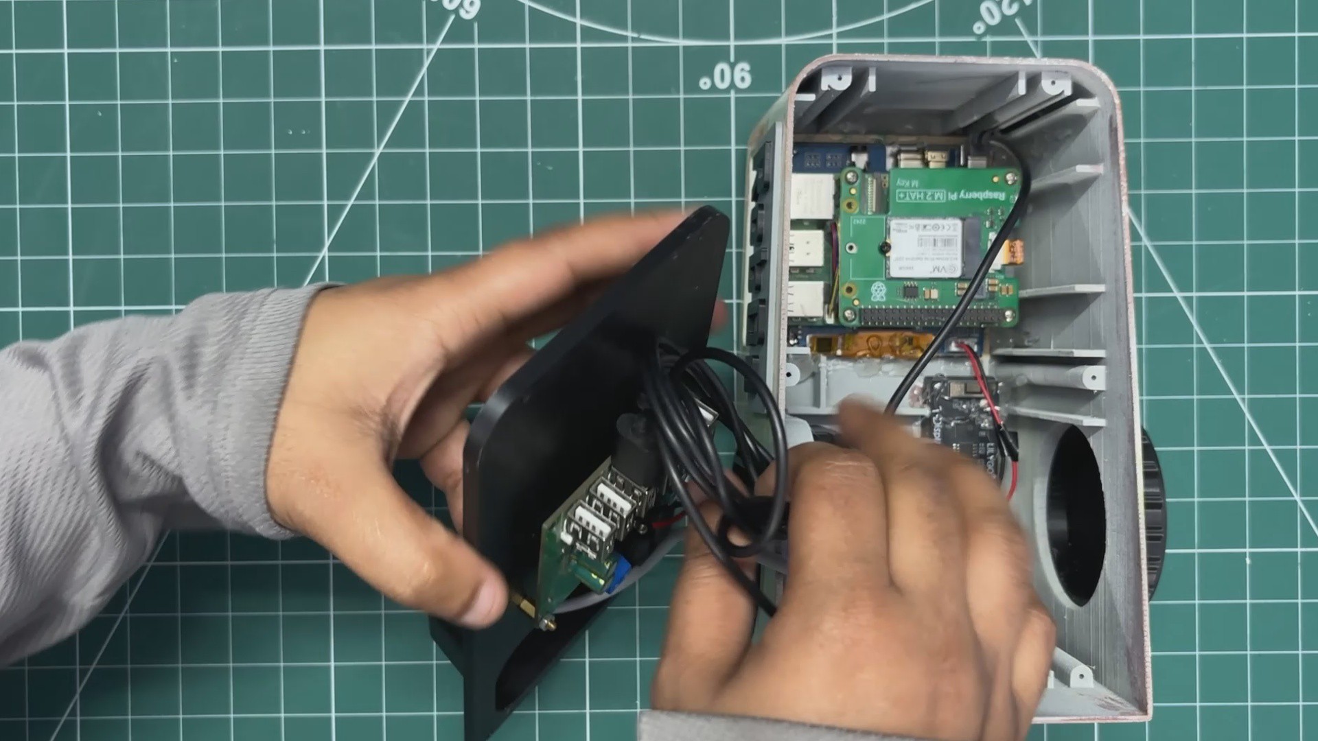
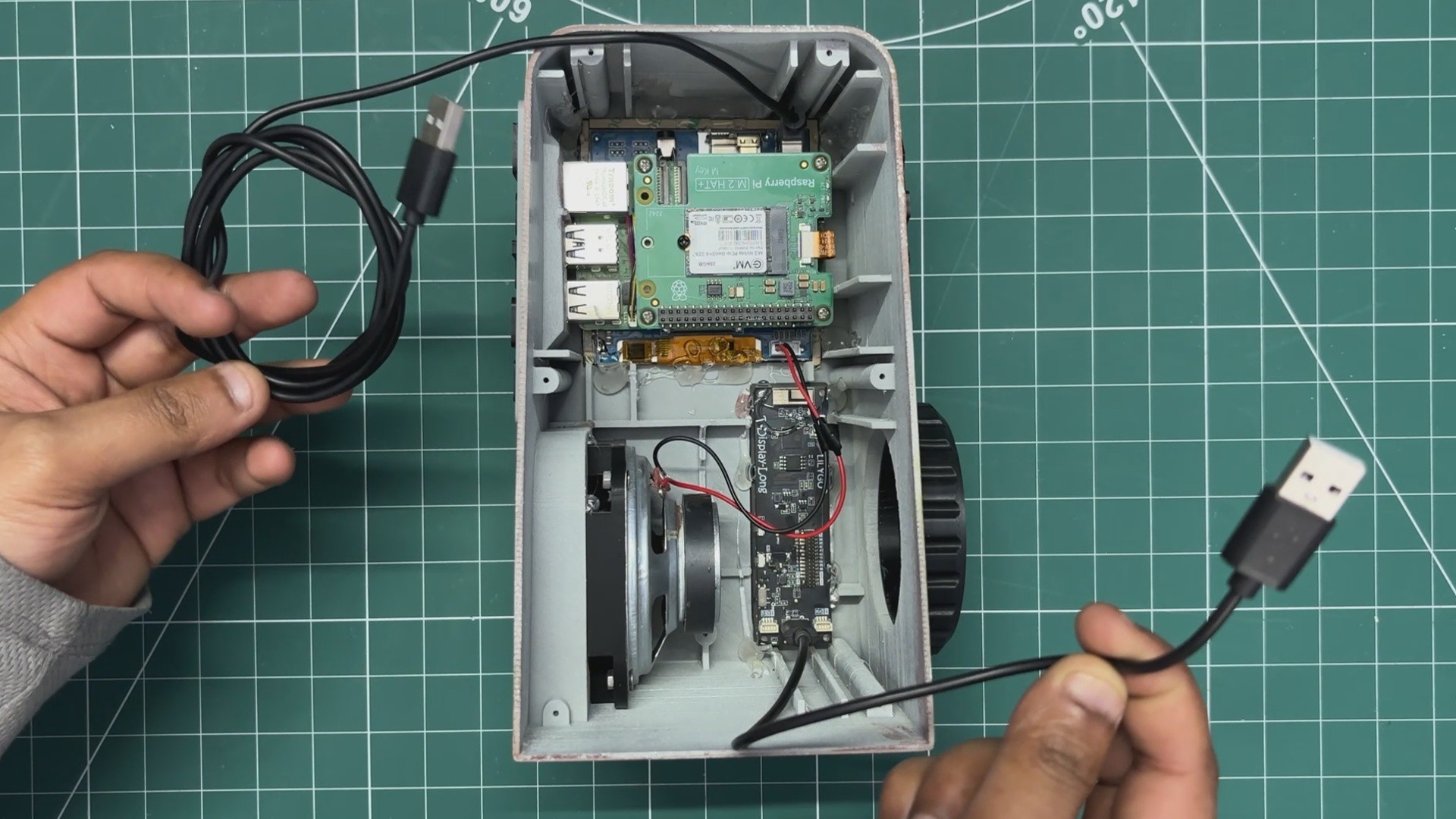
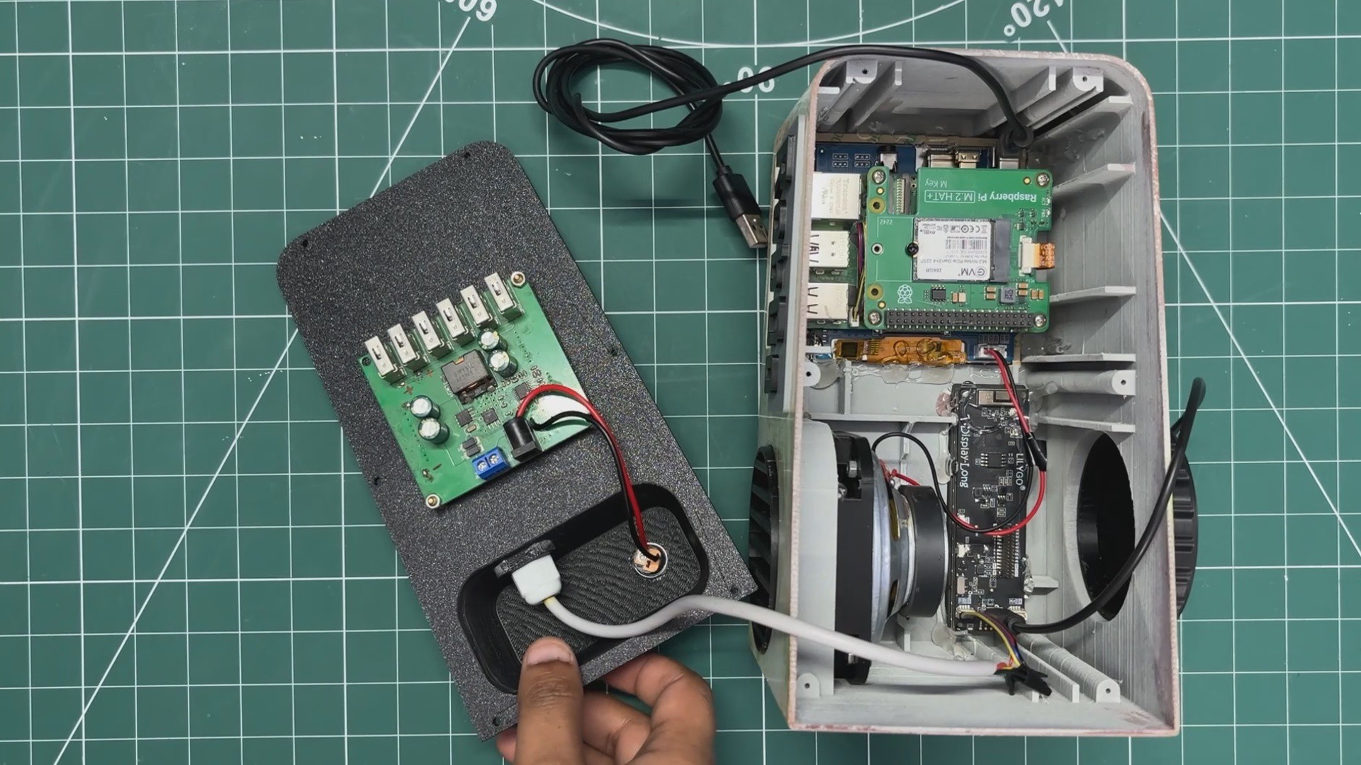
- The final assembly process begins by connecting the SGP40 wiring to the TTGO I2C connector.
- Next, the USB Type-C port from the Waveshare display is plugged into one of the USB ports on the DC step-down module, along with the TTGO Type-C port, which is also connected to the DC step-down module.
- The LED diffuser is then placed into position using tweezers. This diffuser is pressure-fitted and snaps securely into place.
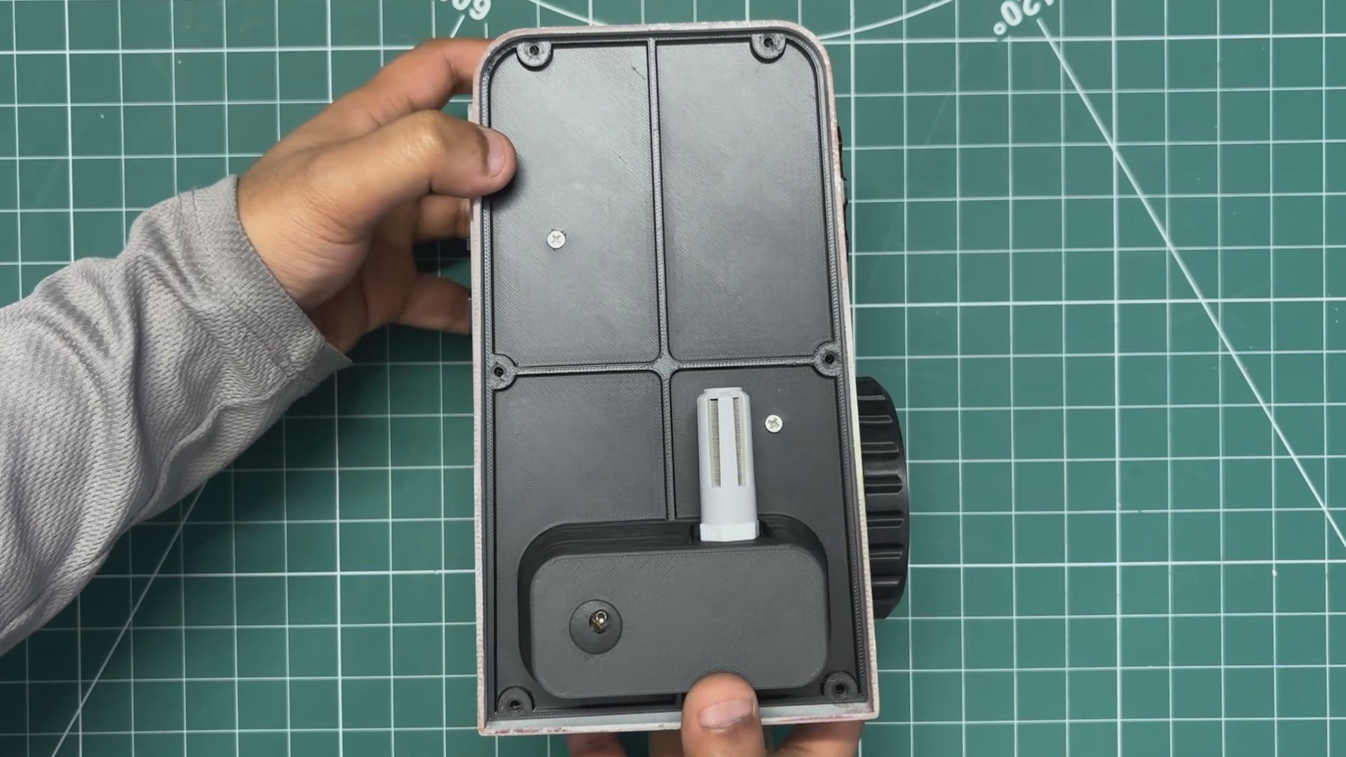
- Once all the connections are done, the lid is placed on the backside of the main body in its position.
- Six M2 screws are then used to fasten the lid to the main body.
With this, the entire project is complete, and the terminal build is finished.
VAULT-TEC Air Terminal
Made a Terminal PC from fallout, powered by Raspberry Pi 5
Discussions
Become a Hackaday.io Member
Create an account to leave a comment. Already have an account? Log In.