 Yann Guidon / YGDES
Let's start with an easy implementation, with the simplest protocol:
- 4 bits in parallel
- 1 bit of bus inversion
- 2 bits of clock (QA, QB)
- 16 bits per word (suitable for mono sound @16 bits or stereo @8bits, or for AI floats, or whatever)
- Easily extended to 32 bits in "OctoDataRate" (ODR) instead of QDR.
As usual, the data precedes the clock transition so the emitting circuit is DDR, running at 1 clock cycle per nibble. So it's "simple, synchronous design" and should not be hard to design.
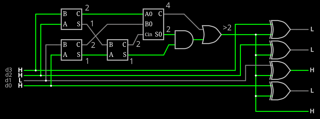
So let's start with MAJ4 to toggle the bus. That makes 5 bits and 6 counts:
- 0, 1, 2 : BI=0
- 3, 4 : BI=1
The circuit here is a reduced version of the previous ones.
Adding the buffer is pretty simple, as shown in this extended circuit:
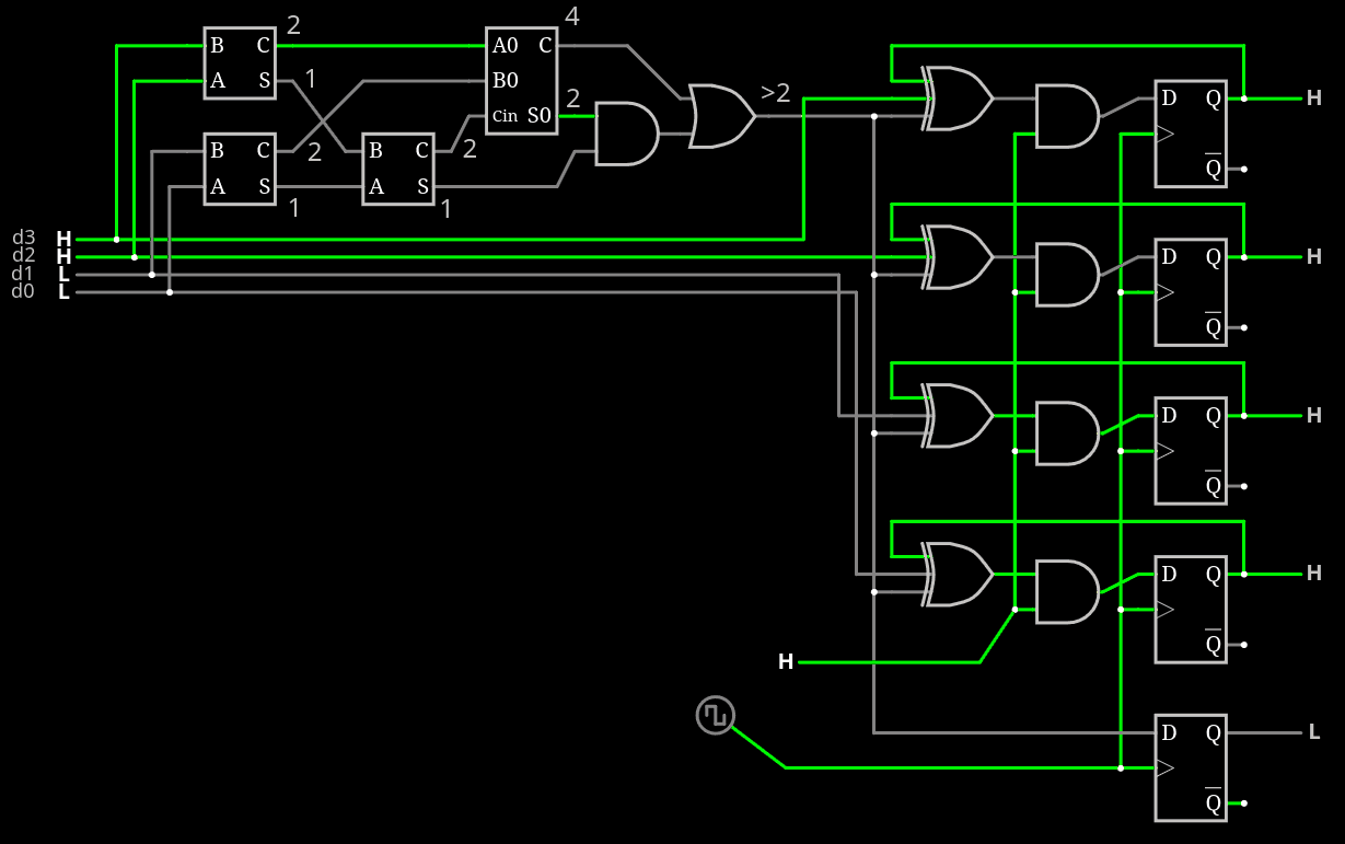
Just be sure that it's possible to synchronously clear the output.
So foor, so gad.
Then it becomes a bit more funky, as the clock generator must be designed. It's based around the classic "quadrature counter" or "2-bit Johnson counter" or "2-bit Gray counter": that's all the same circuit. It must generate at least 4 sequences:
- 4 cycles 2 3 1 0 : data A
- 4 cycles 1 3 2 0 : data B
- 2 cycles : 1 0
- 2 cycles : 2 0
One half can be realised by swapping the outputs with a pair of MUX.
The other half controls how signals are generated and circulate between the registers.
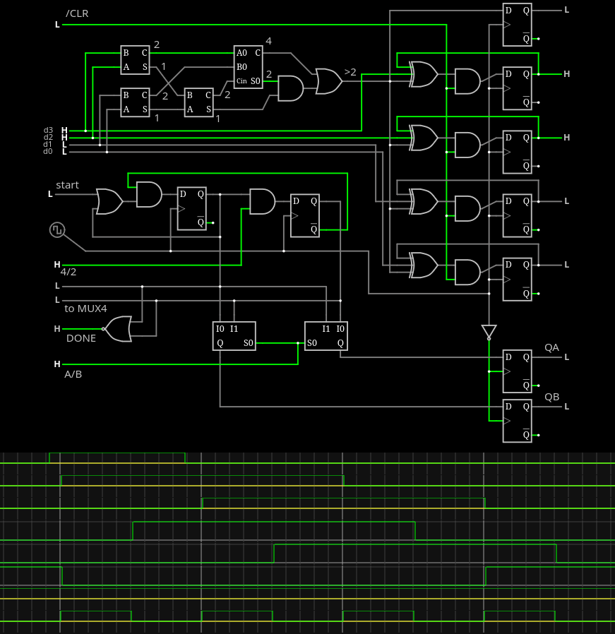
- A/B selects the order/direction.
- START is a one-cycle long pulse that triggers the sequence
- DONE goes high when the sequence is finished (returned to state 0)
- The state is also brought outside to select the nibble using an external MUX4.
- Extension to 32 bits will toggle A/B, which also controls a 32->16 MUX2.
- 4/2 selects the length of the sequence, often used with /CLR to reset the state.
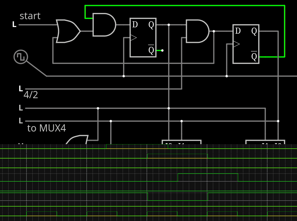
OK I made a tiny mistake for the one-shot sequence, the feedback is behind the AND2:
So all that's left for a transmitter is the 16->4 MUX4, which is quite large/cumbersome with CircuitJS but you get the idea. As you can see:
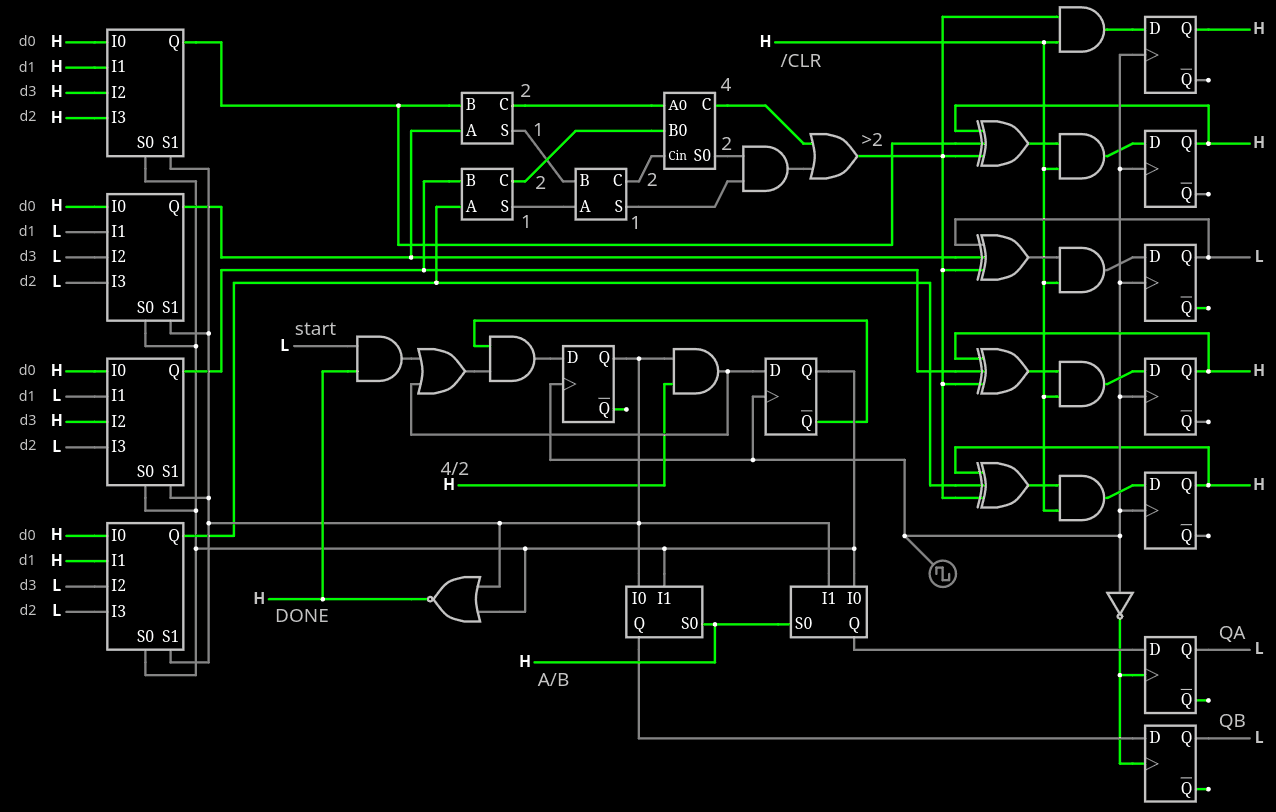
I have added a protection to the START signal so it can only work when DONE.
And then, one still has to design the FSM, but you see it's not difficult with the control and status signals:
- START
- A/B
- 4/2
- /CLR
- DONE
The decoder/receiver is a different pizza party though. This is why I create the "easy" encoder, so I can get the decoder right.
Discussions
Become a Hackaday.io Member
Create an account to leave a comment. Already have an account? Log In.