Close
0%
0%

Pico VGA Board 1.0

Drive VGA/HDMI Monitors with this Raspberry Pi PICO-based Dev board.

Similar projects worth following
0 followers
Greetings everyone, and welcome back!

Today I’ve got something super interesting to show you — the Pico VGA Board.
The heart of this project is a Raspberry Pi PICO W paired with a D-SUB15 connector, and with this setup, we can use a regular TFT monitor as a massive display for pretty much anything we want.

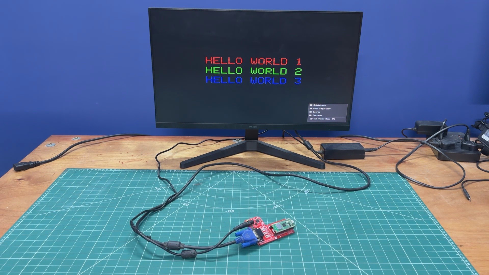
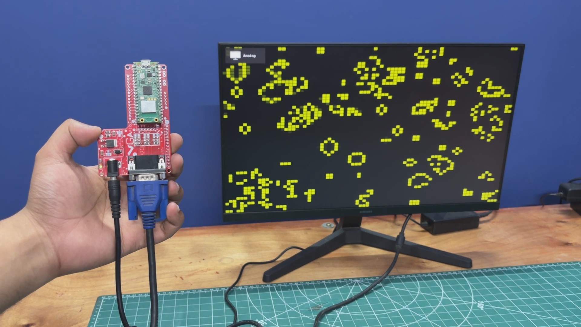
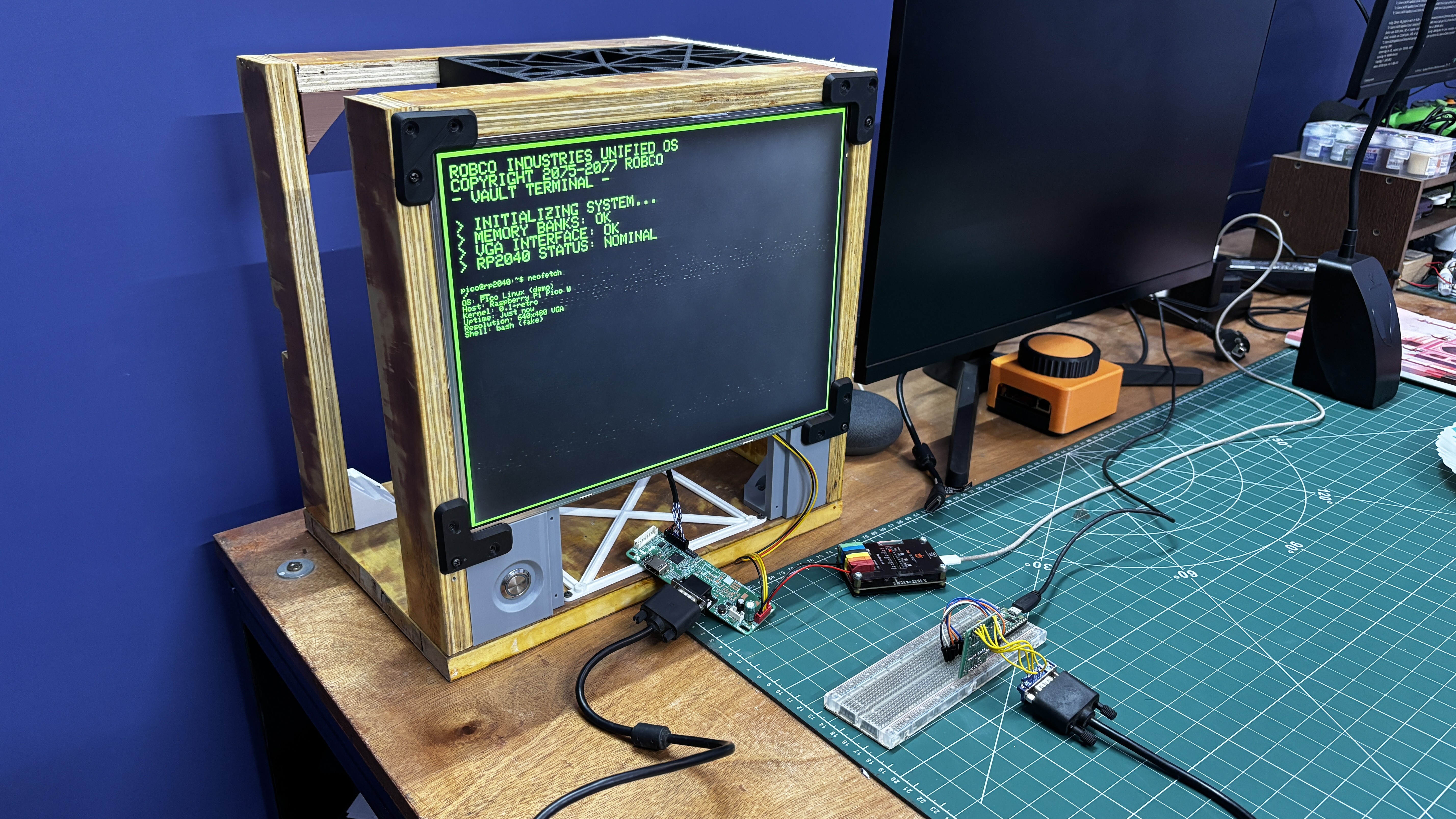
Here's a demo of Conway’s Game of Life running on a full-sized monitor.

The whole project is loosely based around an existing VGA library for PICO, which was made to work with CRT monitors. I made some changes to it so it can be used with modern LCD VGA Monitors.

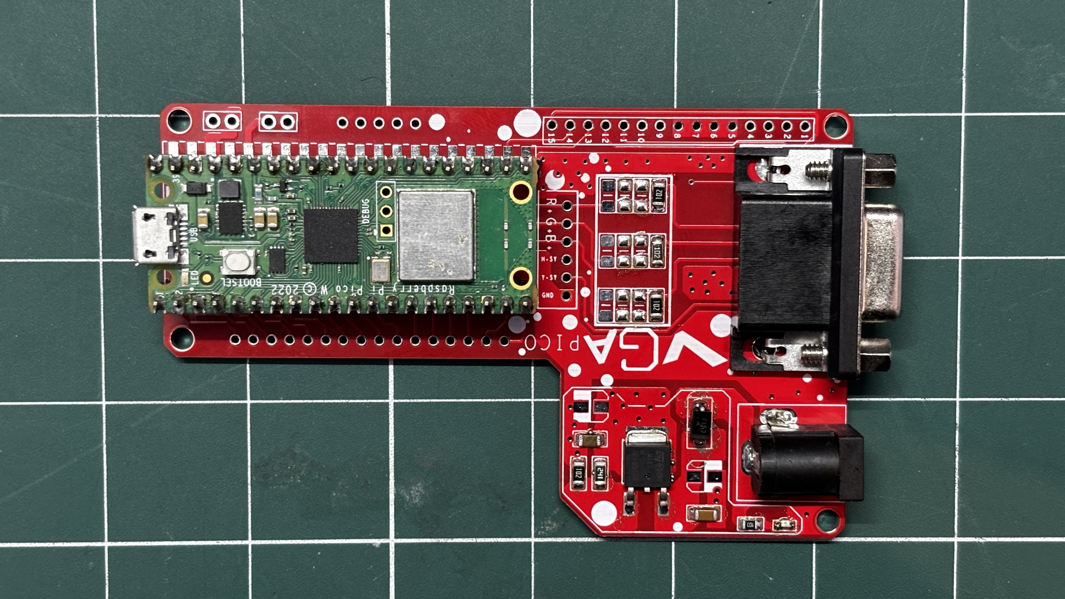
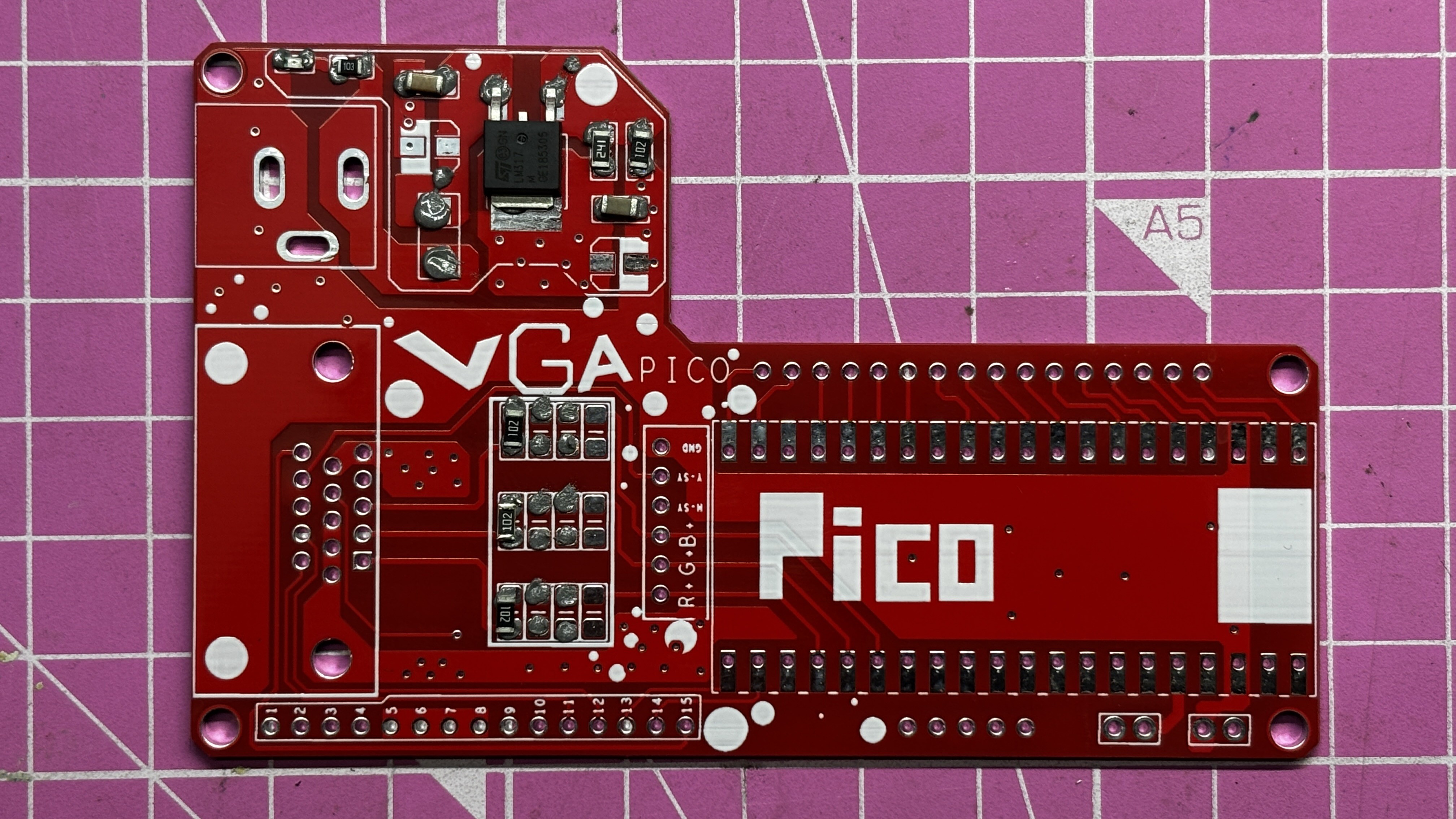
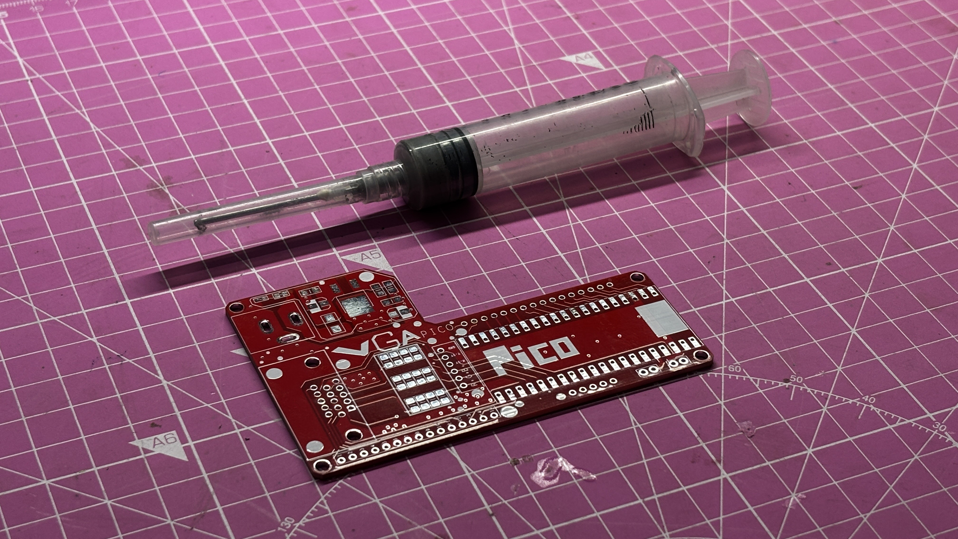
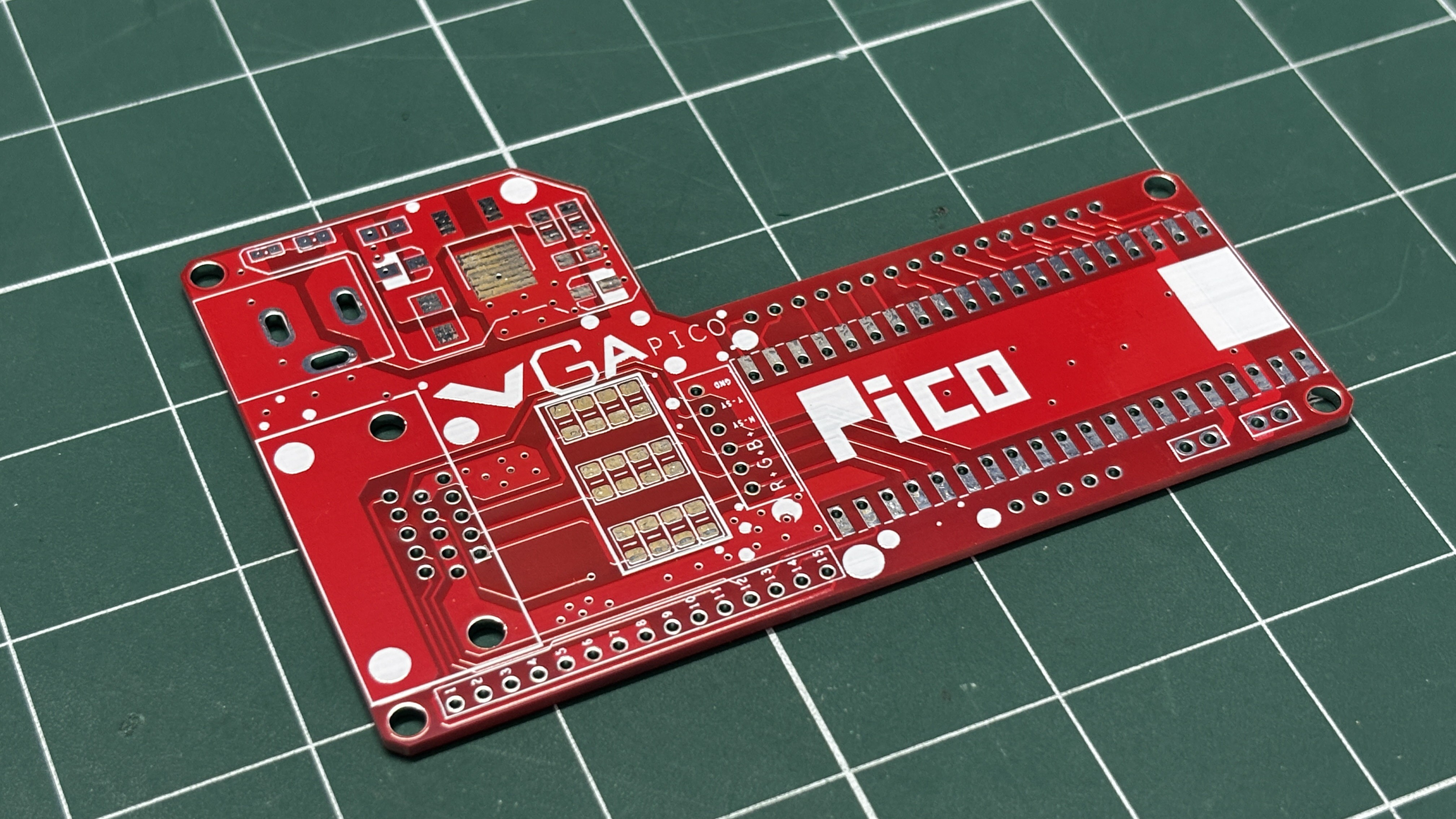
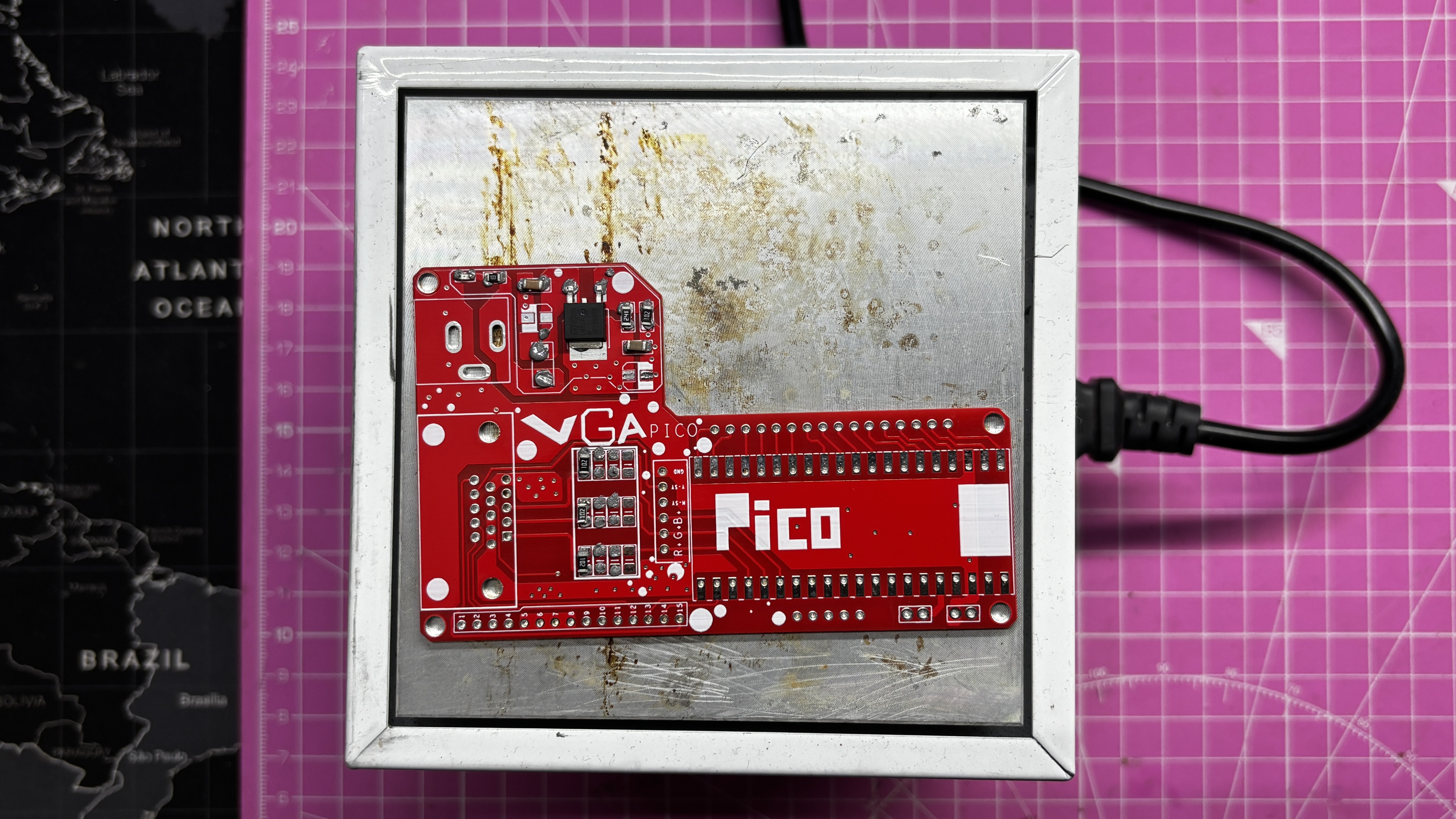
This article covers the complete build process of the PICO VGA Board and walks you through the whole code process.

HOW VGA PORT WORKS

Before starting this project, we first need to understand how VGA ports actually work. VGA, or Video Graphics Array, is an analog video interface that sends image data from a device, such as our Raspberry Pi Pico, to a monitor. Unlike HDMI or DisplayPort, VGA does not send digital packets; instead, it continuously streams voltages that represent colors and timing.

VGA uses three analog signals: Red, Green, and Blue. Each of these signal lines carries a voltage that typically ranges from 0 to 0.7V. At 0V, there is no intensity, and at 0.7V, the monitor displays full intensity.

By combining these three signal lines, the monitor recreates every pixel color. For example, if red is set to 0.7V while green and blue are at 0V, the result is pure red. If all three are set to 0.7V, the result is white.

In addition to RGB signals, VGA uses two digital signals: HSYNC (Horizontal Sync), which tells the monitor when a new line starts, and VSYNC (Vertical Sync), which indicates when a new frame begins.

The monitor draws the image by first rendering pixels from left to right in a single line. An HSYNC pulse then moves it to the next line, and this process repeats for all lines. A VSYNC pulse starts a new frame. This entire process happens approximately 60 times per second (60 Hz).

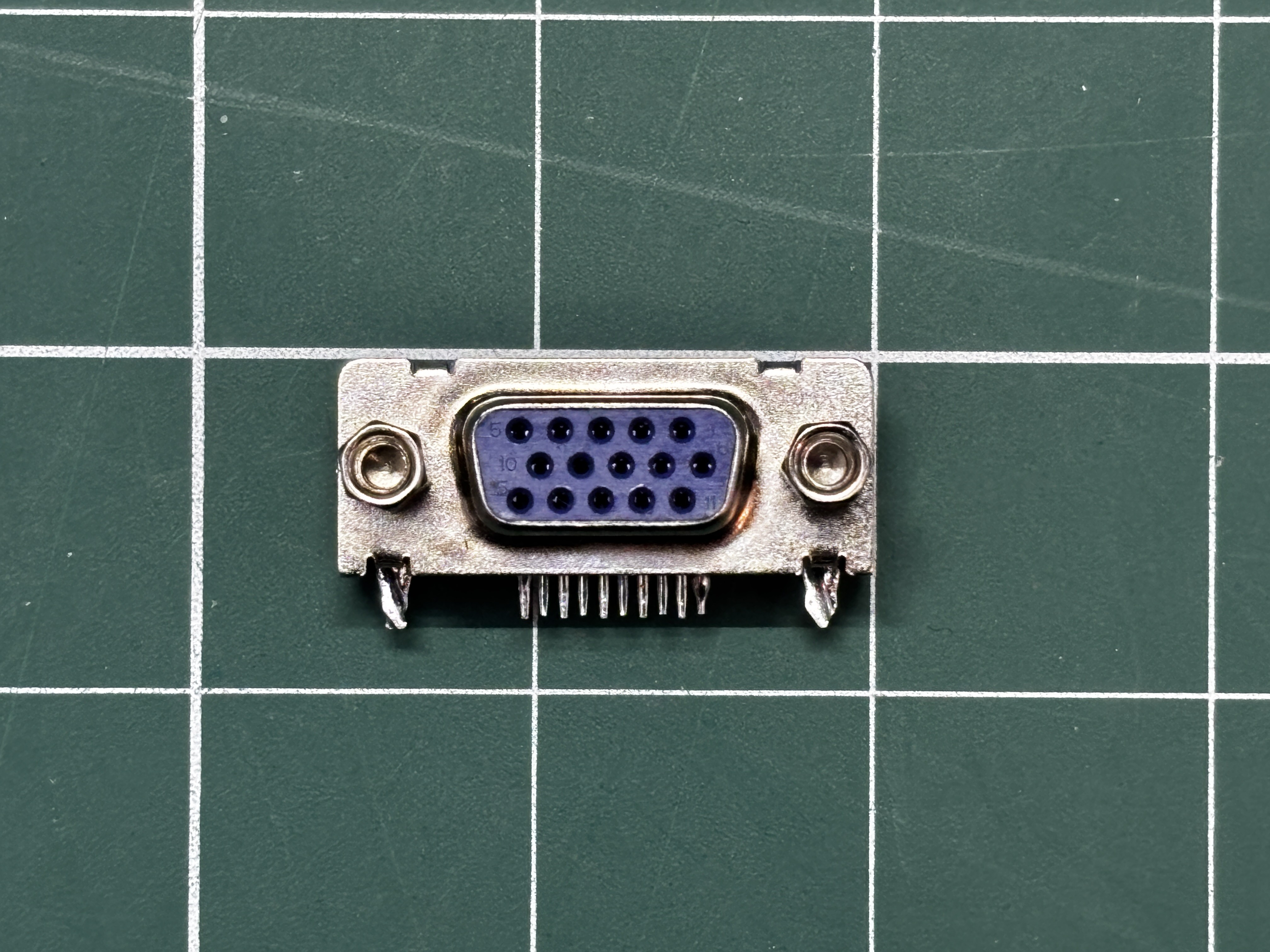
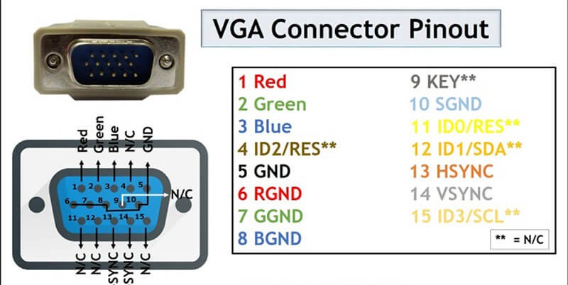
A VGA connector, also known as a D-Sub 15 (DB15) connector, consists of 15 pins. Pin 1 is for Red, Pin 2 for Green, Pin 3 for Blue, Pin 13 for HSYNC, and Pin 14 for VSYNC. The remaining pins are used for ground and other auxiliary functions.

PICO VGA LIBRARY

This project started when I came across a really interesting idea of using a VGA monitor with a Raspberry Pi Pico.

While exploring this, I found a Pico VGA library by Pancrea85. However, the original library was designed primarily for CRT monitors and didn’t work reliably with modern LCD VGA displays.

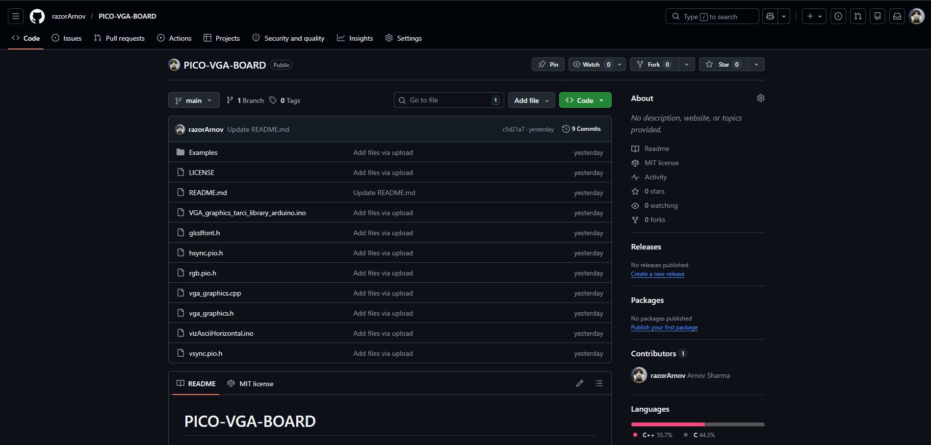
After making several modifications and adding a few example sketches, I created my own version of the library. This version is adapted for better compatibility with modern displays and can be easily installed and used from the GitHub link below.

https://github.com/razorArnov/PICO-VGA-BOARD

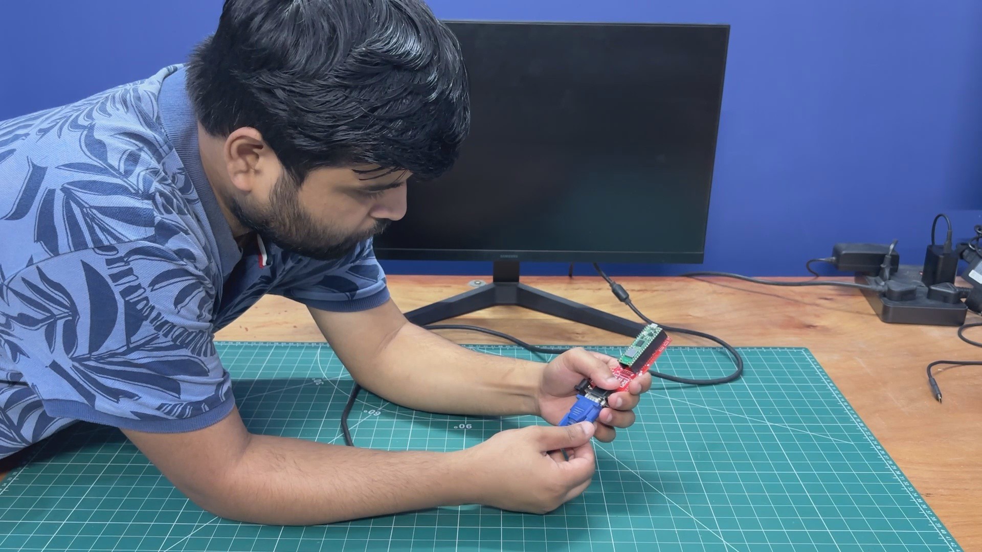
D-SUB15 VGA PORT & PICO BASIC CONNECTION

This is the basic wiring diagram used to interface a VGA monitor with the Raspberry Pi Pico.

  • Pin 1 (Red) of the VGA connector is connected to GPIO18, with four 1kΩ resistors in parallel placed between them.
  • Pin 2 (Green) is connected to GPIO19, with the same four 1kΩ resistors in parallel.
  • Pin 3 (Blue) is connected to GPIO20, again using four 1kΩ resistors in parallel.

The resistance value controls brightness. Higher total resistance results in a dimmer image, while lower resistance increases brightness. An ideal combined resistance is typically in the 200–400Ω range.

  • Pins 5, 6, 7, 8, and 10 are all connected to GND.
  • Pin 13 (HSYNC) is connected to GPIO16.
  • Pin 14 (VSYNC) is connected to GPIO17.

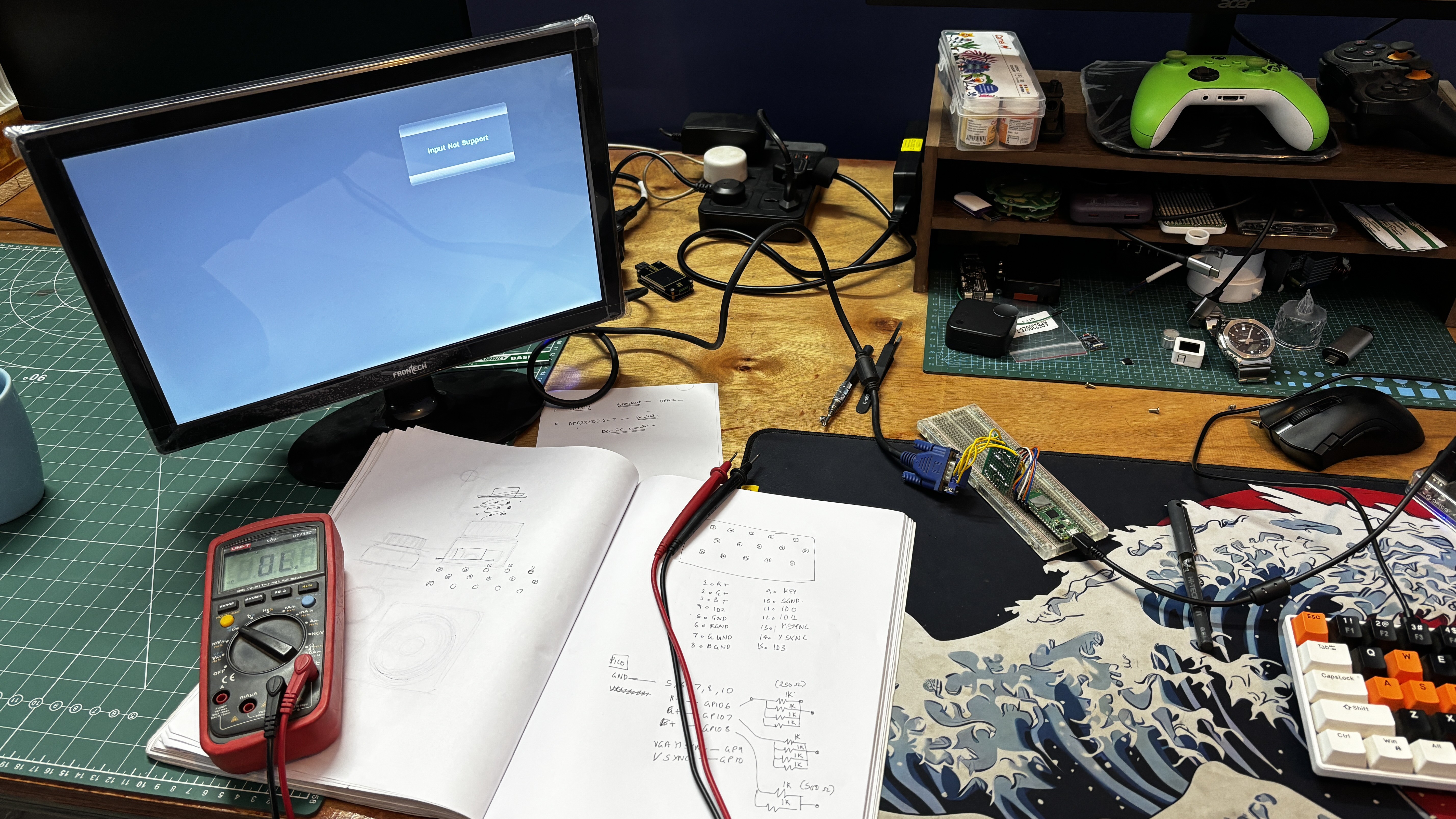
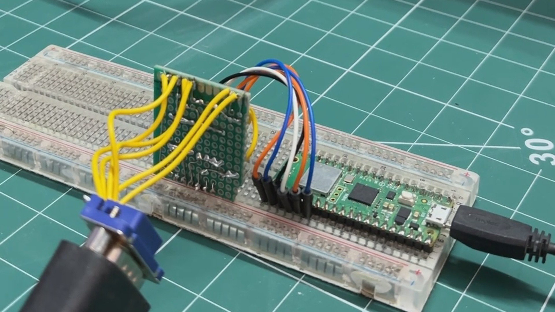
Using the VGA–Pico wiring diagram, we created a simple makeshift breadboard setup. A VGA connector was interfaced using jumper wires, which were connected to a prototype board containing resistor arrays for the RGB and sync lines. These signals were then linked to the Raspberry Pi Pico mounted on a breadboard, forming a complete test setup for VGA output.

BREADBOARD SETUP DEMO

After completing the wiring, we uploaded a custom demo sketch that recreates a Linux-style terminal inspired by Fallout’s RobCo terminals, featuring the same iconic green color theme.

Below is the demo code.

#include "vga_graphics.h"...
Read more »

VGA SCH.pdf

Adobe Portable Document Format - 209.65 kB - 04/12/2026 at 14:31

Preview

  • 1
    PCB ASSEMBLY PROCESS
    • We begin the PCB assembly process by first adding solder paste to each component’s pads one by one using a solder paste dispensing needle. Here, we are using 63/37 SnPb solder paste.
    • We then pick and place each SMD component in its correct location.
    • The PCB is then placed on a reflow hotplate, which heats the PCB from below up to the solder paste melting temperature. As soon as the PCB reaches that temperature, the solder paste melts, and all components are secured in their positions.
    • For the through-hole assembly process, we added the D-Sub 15 connector in its position, followed by the barrel DC jack and two CON20 female header pins in place of the Pico. By turning the board over and using a soldering iron, we solder all the through-hole component leads, securing everything in position.
    • At last, we place the Pico W in its position over the female header pins. This completes the assembly process of the driver board.
  • 2
    GETTING VGA PICO BOARD READY

    Before getting started with the code, we connect our Pico VGA Board to a 24-inch monitor using a VGA cable. We plug the VGA cable from the monitor into the VGA port of our circuit, and then connect the power adapter via the DC barrel jack connector.

  • 3
    DEMO 1- Hello World

    We begin the demo of our setup by flashing PICO W with a Hello World code first.

    This was a simple print statement like skeytch that prints hello world in three different colours, R, G, and B.

    Here's a little code breakdown.

    #include "vga_graphics.h"
    #include <string.h>
    /* ── Screen ───────────────── */
    #define SW 640
    #define SH 480
    /* ── Text scale ──────────── */
    #define SCALE 4
    /* ── Centered print ───────── */
    void printCentered(const char* text, int y, char color) {
    int len = strlen(text);
    int textWidth = len * 6 * SCALE;
    int x = (SW - textWidth) / 2;
    for (int i = 0; i < len; i++) {
    drawChar(x + i * 6 * SCALE, y, text[i], color, BLACK, SCALE);
    }
    }
    /* ── CRT Scanlines ───────── */
    void drawScanlines() {
    for (int y = 0; y < SH; y += 2) {
    drawHLine(0, y, SW, BLACK);  // dark line every other row
    }
    }
    /* ── Setup ─────────────── */
    void setup() {
    initVGA();
    clearScreen();
    int lineHeight = 8 * SCALE;
    int totalHeight = lineHeight * 3 + 20; // spacing included
    int startY = (SH - totalHeight) / 2;
    // Line 1 (RED)
    printCentered("HELLO WORLD 1", startY, RED);
    // Line 2 (GREEN)
    printCentered("HELLO WORLD 2", startY + lineHeight + 10, GREEN);
    // Line 3 (BLUE)
    printCentered("HELLO WORLD 3", startY + (lineHeight + 10) * 2, BLUE);
    // CRT overlay
    drawScanlines();
    }
    /* ── Loop ─────────────── */
    void loop() {
    }

    We begin by defining VGA resolution.

    #define SW 640#define SH 480

    We defined the size of text scaling that enlarges the font size. Default fonts are 6x8 pixels, with a scale of 4; each character becomes 24x32 pixels.

    #define SCALE 4

    This is a center text function that does three major things.

    void printCentered(const char* text, int y, char color)

    It first calculates the width of the text, then centers it horizontally, and then draws each character.

    int textWidth = len * 6 * SCALE;int x = (SW - textWidth) / 2;drawChar(x + i * 6 * SCALE, y, text[i], color, BLACK, SCALE);

    Also, I added a CRT Scanline effect using the following function.

    void drawScanlines()

    How it works is super simple, it just draws a black horizontal line every 2 pixels, which creates a retro CRT Look.

    void drawScanlines()for (int y = 0; y < SH; y += 2)drawHLine(0, y, SW, BLACK);

    In Setup, we print 3 coloured lines.

    printCentered("HELLO WORLD 1", startY, RED);printCentered("HELLO WORLD 2", startY + lineHeight + 10, GREEN);printCentered("HELLO WORLD 3", startY + (lineHeight + 10) * 2, BLUE);

    We apply the CRT effect using below function.

    drawScanlines();

    The loop is kept empty because this is a static display.

View all 6 instructions

Enjoy this project?

Share

Discussions

Does this project spark your interest?

Become a member to follow this project and never miss any updates