ADX: Workhorse Arduino for factories, farms, and offices. Open and tough.
To make the experience fit your profile, pick a username and tell us what interests you.
We found and based on your interests.
SCH_Schematic_2026-05-01.pdfADX Core V0 SchematicAdobe Portable Document Format - 227.27 kB - 04/30/2026 at 15:25 |
|
|
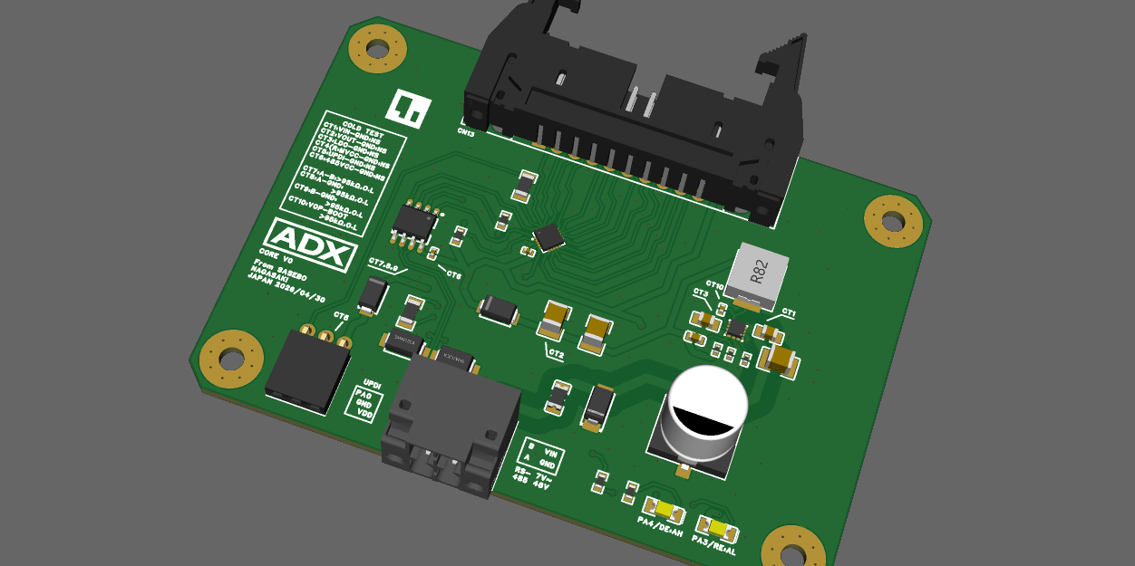
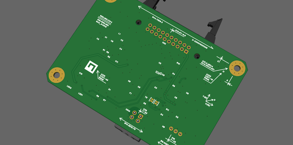
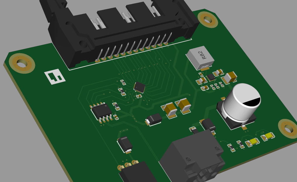
The design phase for the ADX Core V0 is officially complete. I have finalized the schematics and PCB layout, and the project has moved into the manufacturing stage. The PCBA (Printed Circuit Board Assembly) order has been placed with JLCPCB.
All design files, fabrication data (Gerbers, BOM, CPL), and detailed development history are available on GitHub:
Repository:
Note: The repository contains documentation and commit messages in a mix of English and Japanese.
The ADX Core V0 is designed as an "Arduino-like" industrial control board. It introduces a new, standardized industrial form factor—inspired by the ATX philosophy—aimed at creating an ecosystem where enclosures and components are easily interchangeable and professional.
| Item | Specification | Notes |
| MCU | Microchip ATtiny1616-MNR | 8-bit AVR® megaAVR 0-series |
| Clock Speed | 20 MHz (16 MHz recommended) | Internal clock |
| Logic Voltage | 5 V | |
| Memory | Flash 16 KB / SRAM 2 KB / EEPROM 256 B | |
| Operating Temp | -40°C to +105°C | Industrial grade components |
| Item | Specification | Notes |
| Nominal Input | DC 12 V / 24 V / 48 V systems | |
| Input Range | DC 7.0 V to 48.0 V | |
| Protection | SMD Chip Fuse / Reverse Polarity | |
| Surge Protection | TVS Diodes | Mounted on power input |
| Connection | 2-pin Push-in Terminal | Pluggable with lock lever |
| Item | Specification | Notes |
| Protocol | RS-485 x 1 channel | |
| Protection | TVS Diodes | A / B line protection |
| Programming | UPDI | 3-pin socket (UPDI, VDD, GND) |
Connector: 2×10 pin Locked IDC Box Header (Right Angle)
The layout utilizes multiple GND and VDD pins to ensure signal integrity and stable wiring in industrial environments.
| Pin | Signal | Notes | Pin | Signal | Notes |
| 1 | VDD | 5V Out | 2 | GND | Ground |
| 3 | PC3 | GPIO | 4 | PC2 | GPIO |
| 5 | PC1 | GPIO | 6 | PC0 | GPIO |
| 7 | GND | Ground | 8 | PB0 | GPIO |
| 9 | PB1 | GPIO | 10 | PB2 | GPIO |
| 11 | PB3 | GPIO | 12 | GND | Ground |
| 13 | PB4 | GPIO | 14 | PB5 | GPIO |
| 15 | GND | Ground | 16 | PA7 | GPIO |
| 17 | PA6 | GPIO | 18 | PA5 | GPIO |
| 19 | GND | Ground | 20 | VDD | 5V Out |
Once the boards arrive from the fab, I will proceed with:
Currently, many "Industrial Arduinos" (such as the Arduino Opta) are emerging, but they suffer from a fundamental flaw: they are becoming "PLC Lite." In their pursuit of being "official industrial products," they have inherited the "black box" nature of traditional vendors—closed enclosures, rigid board-to-board (B2B) connectors, and limited extensibility. I call this "Mechanical Debt." While it offers reliability, it kills the open-source spirit that made Arduino great in the first place.
- ADX-Core v0 proto
ADX is my attempt to break this cycle. Here is how I am designing it to be different:
Read more »
Create an account to leave a comment. Already have an account? Log In.
Become a member to follow this project and never miss any updates