Masahiro Furukawa
-
ADX Core V0 Design Freeze and PCBA Order Placed
04/30/2026 at 15:16 • 0 commentsProgress Report: ADX Core V0 Design Freeze and PCBA Order Placed
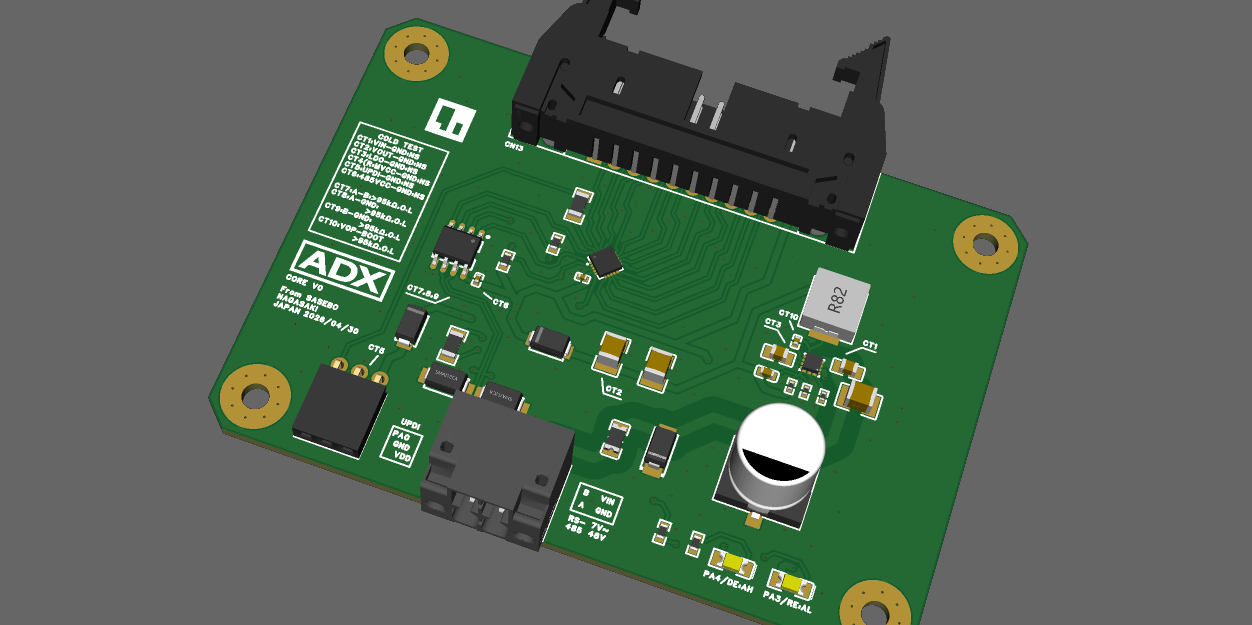
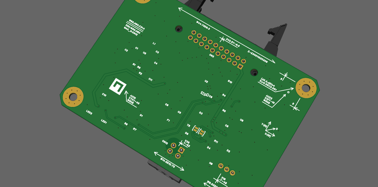
The design phase for the ADX Core V0 is officially complete. I have finalized the schematics and PCB layout, and the project has moved into the manufacturing stage. The PCBA (Printed Circuit Board Assembly) order has been placed with JLCPCB.
![]()
![]()
Status Update
- Schematics: Completed
- PCB Layout: Completed
- Manufacturing: In progress (Ordered via JLCPCB PCBA service)
- Target Grade: Industrial / Robust Control
Project Resources & Documentation
All design files, fabrication data (Gerbers, BOM, CPL), and detailed development history are available on GitHub:
Repository:
- https://github.com/Masafuro/ADX/
Note: The repository contains documentation and commit messages in a mix of English and Japanese.
Hardware Specifications
The ADX Core V0 is designed as an "Arduino-like" industrial control board. It introduces a new, standardized industrial form factor—inspired by the ATX philosophy—aimed at creating an ecosystem where enclosures and components are easily interchangeable and professional.
1. Performance Specifications
Item Specification Notes MCU Microchip ATtiny1616-MNR 8-bit AVR® megaAVR 0-series Clock Speed 20 MHz (16 MHz recommended) Internal clock Logic Voltage 5 V Memory Flash 16 KB / SRAM 2 KB / EEPROM 256 B Operating Temp -40°C to +105°C Industrial grade components 2. Power & Protection
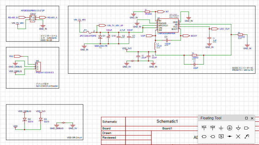
Item Specification Notes Nominal Input DC 12 V / 24 V / 48 V systems Input Range DC 7.0 V to 48.0 V Protection SMD Chip Fuse / Reverse Polarity Surge Protection TVS Diodes Mounted on power input Connection 2-pin Push-in Terminal Pluggable with lock lever 3. Communication & Interface
Item Specification Notes Protocol RS-485 x 1 channel Protection TVS Diodes A / B line protection Programming UPDI 3-pin socket (UPDI, VDD, GND) 4. GPIO Pin Assignment
Connector: 2×10 pin Locked IDC Box Header (Right Angle)
The layout utilizes multiple GND and VDD pins to ensure signal integrity and stable wiring in industrial environments.
Pin Signal Notes Pin Signal Notes 1 VDD 5V Out 2 GND Ground 3 PC3 GPIO 4 PC2 GPIO 5 PC1 GPIO 6 PC0 GPIO 7 GND Ground 8 PB0 GPIO 9 PB1 GPIO 10 PB2 GPIO 11 PB3 GPIO 12 GND Ground 13 PB4 GPIO 14 PB5 GPIO 15 GND Ground 16 PA7 GPIO 17 PA6 GPIO 18 PA5 GPIO 19 GND Ground 20 VDD 5V Out 5. Mechanical Specifications
- Dimensions: 85.0 mm × 60.0 mm
- Mounting: 4 x M3 screw holes (corners)
- Features: 8.0 mm washer clearance, C3 chamfered edges.
Next Steps
Once the boards arrive from the fab, I will proceed with:
- Power rail verification: Testing stability with 24V and 48V inputs.
- Firmware upload: Initializing the ATtiny1616 via UPDI.
- Stress testing: RS-485 communication reliability in high-noise environments.
-
Beyond "PLC Lite": Designing for "Soft Coupling" and Openness
04/21/2026 at 23:49 • 0 commentsBeyond "PLC Lite": Designing for "Soft Coupling" and Openness
Currently, many "Industrial Arduinos" (such as the Arduino Opta) are emerging, but they suffer from a fundamental flaw: they are becoming "PLC Lite." In their pursuit of being "official industrial products," they have inherited the "black box" nature of traditional vendors—closed enclosures, rigid board-to-board (B2B) connectors, and limited extensibility. I call this "Mechanical Debt." While it offers reliability, it kills the open-source spirit that made Arduino great in the first place.
![]()
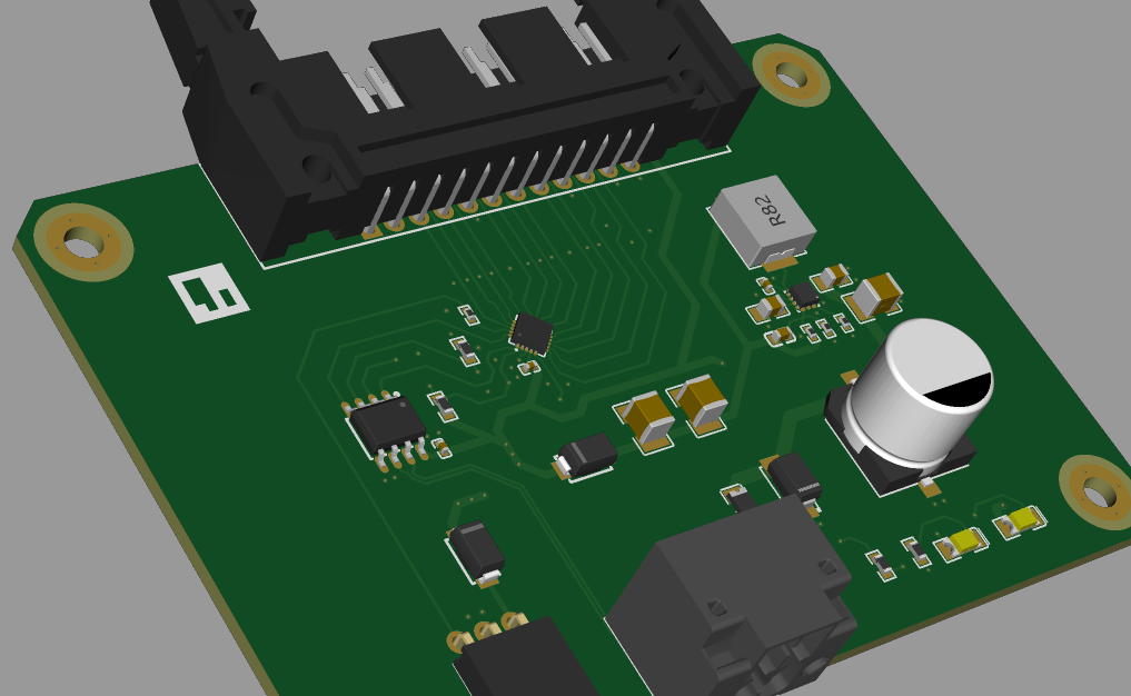
- ADX-Core v0 proto
ADX is my attempt to break this cycle. Here is how I am designing it to be different:
---------- more ----------1. The "Soft Coupling" Strategy: Why IDC24?
Instead of rigid B2B connectors that lock you into a specific proprietary enclosure, ADX utilizes a locking IDC24 connector.
- Why? To allow for physical "play." By using ribbon cables to connect to expansion modules, we decouple electronic reliability from the sub-millimeter precision of a plastic case.
- This is my vision for an "Industrial ATX"—a world where the controller and the housing are independent. You should be able to mount it on a DIN rail, a camera screw, or even zip-ties without losing connectivity.
2. Choosing the ATtiny1616-MNR
I chose the ATtiny1616 as the heart of ADX because it is simply the most practical "Modern-Classic" chip for the field.
- Cheap & Abundant: It is extremely affordable and has excellent stock availability worldwide. No more supply chain headaches when you need to scale.
- Industrial Temperature Range: It natively supports -40°C to +105°C, making it tough enough for factory floors and outdoor agricultural use right out of the box.
- Arduino IDE Ready: Thanks to megaTinyCore, you can develop with the familiarity of the Arduino IDE while leveraging the modern features of the tinyAVR 1-series.
3. The Path to PL4 (Power over LIN based RS-485)
On-board RS-485 is standard, but the ultimate goal for ADX is a field network I call PL4. It is a LIN-based RS-485 architecture that can carry power over distances up to 1,000 meters. In environments where Wi-Fi is unreliable and cables run long, we don't need "fragile" connections—we need raw, stable communication.
![]()
![]()
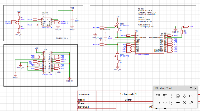
- Current circuit diagram
Stay Updated & Feedback Welcome
ADX is still in its early stages, and I’ll be sharing my progress, technical iterations, and lessons learned here as I go. I’m also documenting the nitty-gritty technical details and deeper philosophy on my development blog:
I’m looking forward to building this in the open, so please feel free to chime in with your thoughts, suggestions, or questions in the comments. Any feedback is welcome as the project evolves!
ADX : Industrial ATtiny board, Arduino IDE Ready.
ADX: Workhorse Arduino for factories, farms, and offices. Open and tough.