Having semi-finalised the idea in my head I thought it was time to take a note of it, before I forget or change my mind again :-)
Here's what I have come up with:

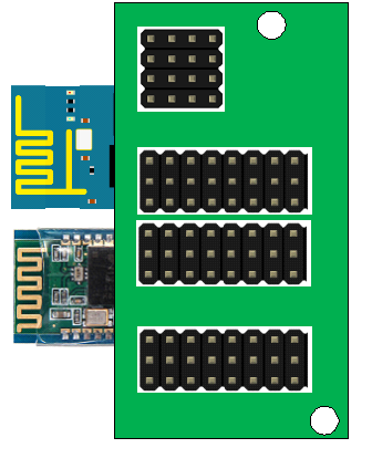
This is a very primitive drawing done using Microsoft Paint so please excuse the roughness of it.
The board will fit over the lower end of the Mega, plugging into the communication pins, digital pins and analog pins. The mounting holes are there for guidance.
The ESP8266 & Bluetooth modules will be soldered underneath, overlapping the board somewhat. The overhang would fit under the arduino shield mounted alongside it.
On the top there are banks of pins:
- 4x4: i2c pins (SDA, SCL, 5v, GND)
- 8x3, 8x3: Digital Pins (D22-D52 even pins, 5v/3.3v, GND)
- 8x3: Analog Pins (A8-A15, 5v, GND)
I would also like to add the option to connect an external power source to help power all the potential extra devices if necessary.
If anyone is interested in helping me produce a board that would be greatly appreciated! ( @davedarko, nudge nudge, wink wink ;-) ) that would be amazing!
Cheers
 Craig Hissett
Discussions
Become a Hackaday.io Member
Create an account to leave a comment. Already have an account? Log In.
hmmm. Placing the boards right where the pinheaders are is a bit tricky ;)
Esp12 or esp01?
Are you sure? yes | no
Ha ha, I never said my drawing was feasible :-)
Obviously the bottom-mounted boards can go anywhere to fit, and the headers on the top can also go anywhere too. For the ESP I am easy; whichever one is lower profile and easier to use for you :-)
Are you sure? yes | no
They are so neatly arranged - I was unsure ;)
Are you sure? yes | no
Thank you for noticing :-)
I was just aiming to demonstrate a group of i2c, analog and digital pins for ease of use, heh heh.
Are you sure? yes | no
Note to self: look at ESP32 to handle both Bluetooth and Wifi over one serial connection. Will leave one serial port free to be broken out ok top of board.
Are you sure? yes | no