-
PCB Design skillz required
06/13/2017 at 13:18 • 0 commentsApologies for the lack of updates on this project.
I'm still looking to find the time to invest in learning how to draw up a schematic and how to design a pcb.
Once that's done I can get the board ordered and soldered up ready to go.
I can't bloody wait to get this working!
-
Board Design ideas
05/02/2017 at 15:46 • 5 commentsHaving semi-finalised the idea in my head I thought it was time to take a note of it, before I forget or change my mind again :-)
Here's what I have come up with:
![]()
This is a very primitive drawing done using Microsoft Paint so please excuse the roughness of it.
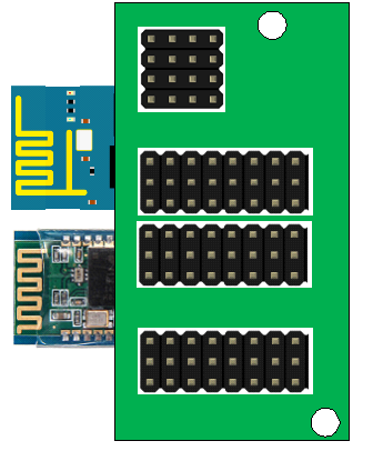
The board will fit over the lower end of the Mega, plugging into the communication pins, digital pins and analog pins. The mounting holes are there for guidance.
The ESP8266 & Bluetooth modules will be soldered underneath, overlapping the board somewhat. The overhang would fit under the arduino shield mounted alongside it.
On the top there are banks of pins:
- 4x4: i2c pins (SDA, SCL, 5v, GND)
- 8x3, 8x3: Digital Pins (D22-D52 even pins, 5v/3.3v, GND)
- 8x3: Analog Pins (A8-A15, 5v, GND)
I would also like to add the option to connect an external power source to help power all the potential extra devices if necessary.
If anyone is interested in helping me produce a board that would be greatly appreciated! ( @davedarko, nudge nudge, wink wink ;-) ) that would be amazing!
Cheers
-
Wifi Serial
04/24/2017 at 19:21 • 0 commentsSo, delivery #1 of many arrived today; 3 ESP07-based serial boards.
With only Tx, Rx, power and ground pins broken out, this board is controlled via AT and over a serial connection.
This is perfect for this project - added to the Serial1 port of the Mega it will make wifi comms easy!
I am going to adapt the Arduino sketch of the project I previously shared to process an 'ESP_' command, and forward the following string (which will be the AT command) straight to Serial1.
In addition I am going to write a python based GUI, along the lines of the previous link's C# application. This is to practice writing python GUI apps, and also to write something that works cross platform.
Will post my results Tommorrow, all being well!
-
Look at this!
04/22/2017 at 15:51 • 0 commentsstill waiting on a few bits and bobs to start putting together my projects, so started thinking about perhaps creating software to accompany this device, and making its use simple.
Found this little beauty, which will enable a fantastic start!
-
ESP Spree!
04/03/2017 at 15:00 • 0 commentsThat monthly sacred day known as Pay Day has arrived.
I've ordered a few different types of ESP8266 based boards for my various projects:
- A few NodeMCU boards with a view to potentially running my #GBAA: Game Boy Advance Arduino project.
- A few ESP-01 modules to use as plug-in modules with my #Aquariumatic project
- And for this, my #Arduino Mega Expansion board, an ESP-07 based serial port board.
The board I have ordered is nice and slim, and only has the serial port pins (tx/rx/5v/gnd) broken out. This is perfect for this as I can simply add a rightangled female header and plug this board in to keep a really low profile under the board. I've always planned on connecting the serial pins up to TX1/RX1 on the mega so there's no need for any other headers.
Good times!
-
Rough layouts for boards
03/22/2017 at 18:17 • 1 commentJust at work so had to use Excel to map my plans before I forgot ha ha!
![]()
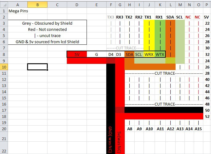
Row 8 details the header for the Wemos D1 mini, and where it will sit on my perfrboard in relation to the Mega pins. It shall be mounted underneath, keeping the top free for Analog, Digital and i2c headers.
TX1 and RX1 go straight to the RX and TX pins of the D1 mini, with the SDA and SCL lines routed to meet pins D2 and D1 on the Wemos board.
5v and ground lines are added to the left of the board where no other pins are connected.
As you can see the 5v and the Ground pins of the Wemos will stick out underneath the board, but that is fine; in order to remove it you will need to remove the arduino shield first, and to install it you will have to plug in the expansion board first.
Arduino Mega Expansion board
A mini shield-like add-on for the Arduino Mega designed to add wifi/Bluetooth connectivity and more alongside the standard Uno-sized shield.
 Craig Hissett
