Close
0%
0%

nTerm2-S

A terminal emulator of my own liking. Using an ESP32, connecting to a VGA screen, and having sound. Based on the uTerm2-S and FabGL.

Similar projects worth following
This is a terminal emulator board using an ESP32 with emulator software based on the FabGL library. It can connect to a VGA screen, uses a PS/2 keyboard (and mouse), and has an RS232-V24 compatible serial port. It also features an option to switch between a normal connection or a null-modem connection, eliminating the need to find that null-modem cable that is never where you last left it, or that patch box of which a few wires always seem to have come loose by themselves since the last time you patched it to work as a null-modem converter.

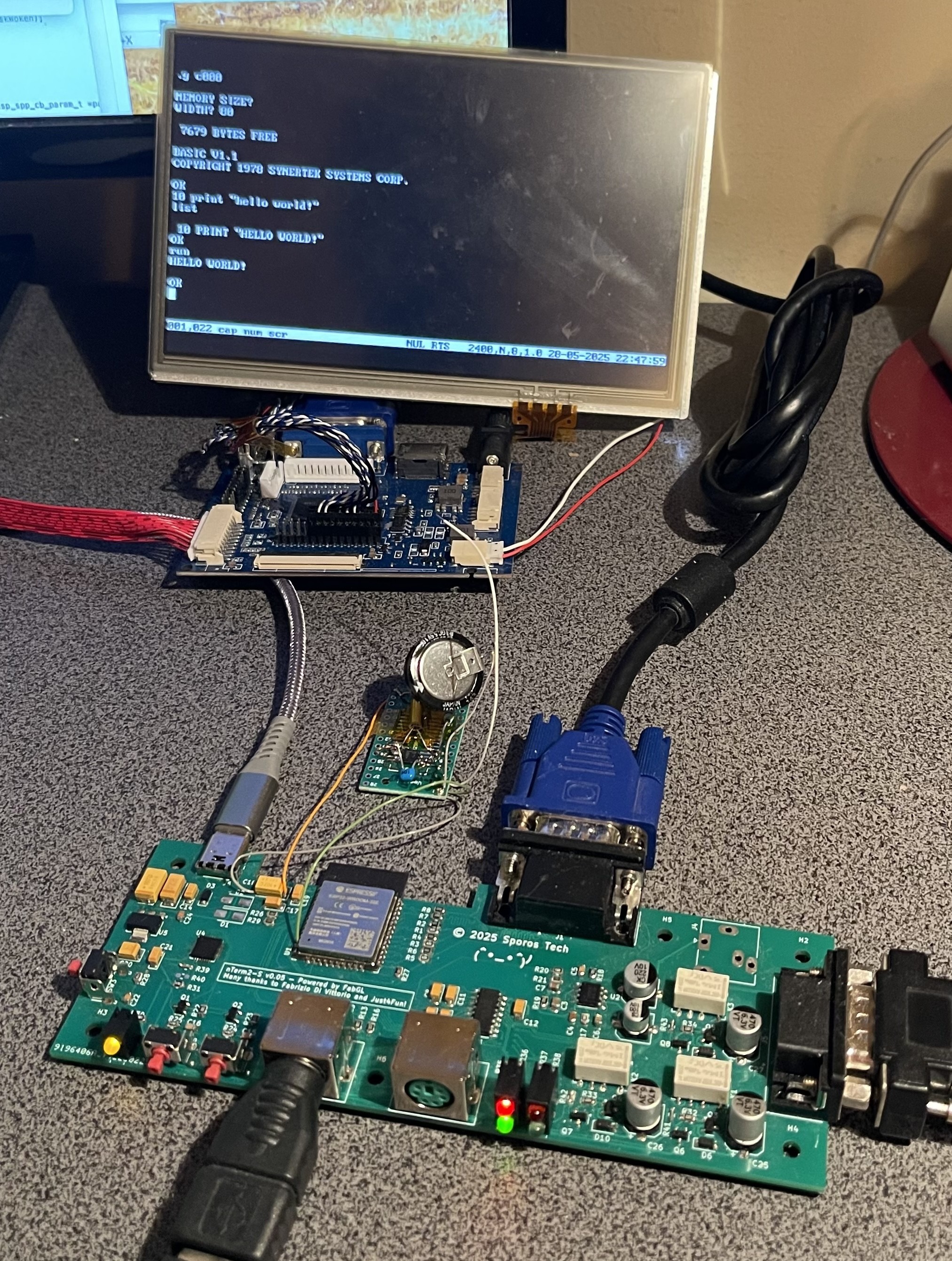
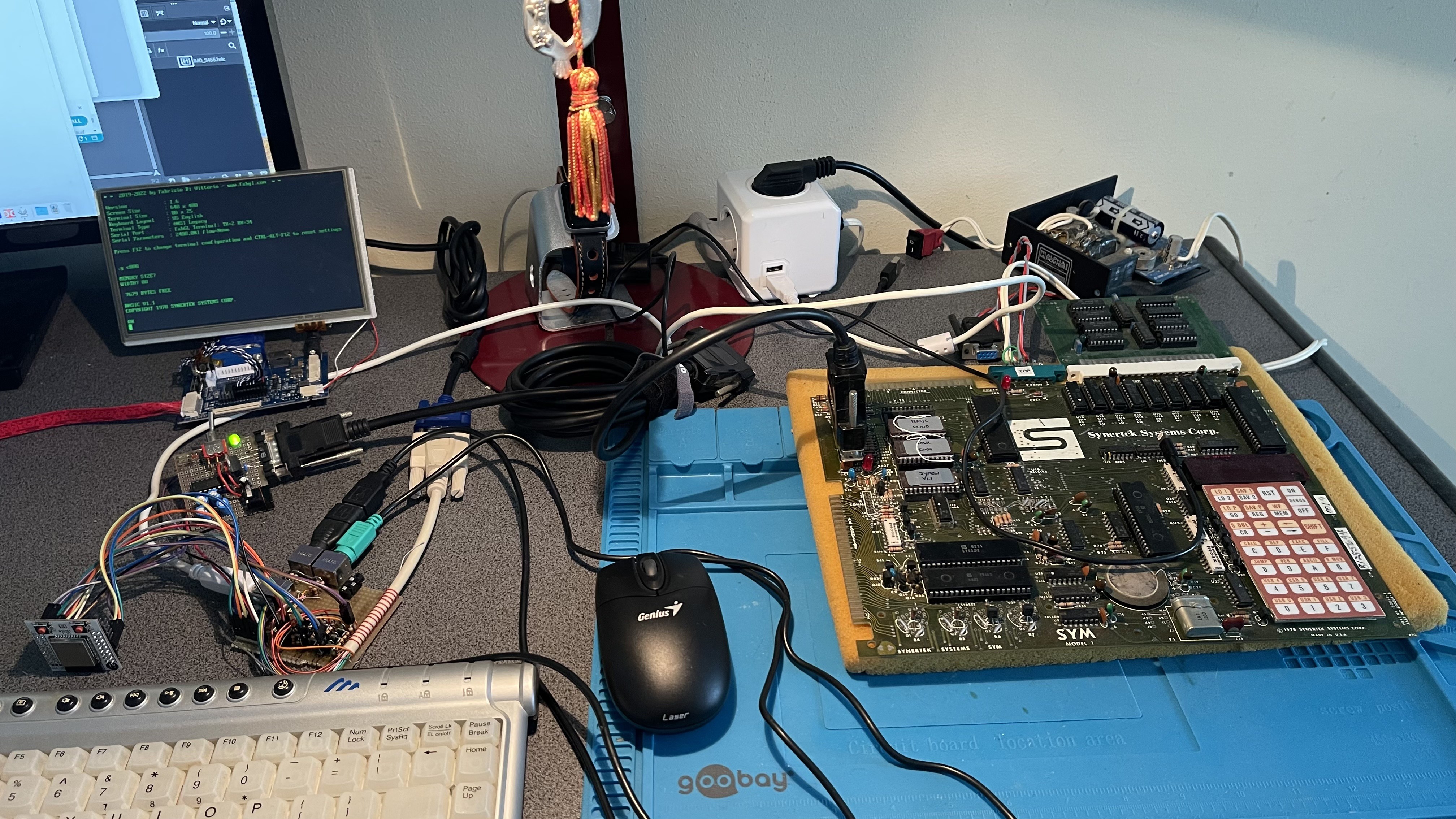
Some time ago I was working on a Minato 1866 Eprom Programmer, and a SYM-1 single-board computer. Both can only communicate with the operator through a keypad and 6 digits of LED displays.

Or... RS-232 V24.

I found myself having either one laptop connected to it and annoyingly having to switch back and forth between a terminal emulator and the web browser, or two laptops where one was talking to the device and the other showing docs. Also using a bunch of adapters, and making sure to use an RS232 to USB dongle that can handle +/-12V. Not optimal. So I started thinking if there was something better.

After looking around, I found out about the uTerm2-S and FabGL. That looked very close to what I was looking for, and I almost bought a uTerm2-S board.

However... I was looking for a worthwhile hardware project to brush up on my long-unused hardware development skills anyway, or more honestly: my long-unused PCB design skills.

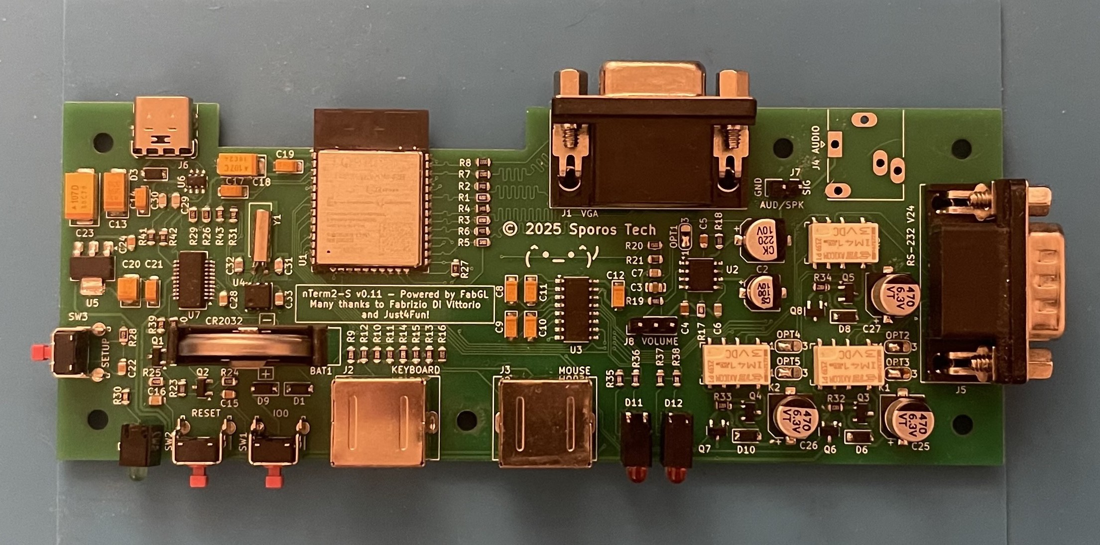
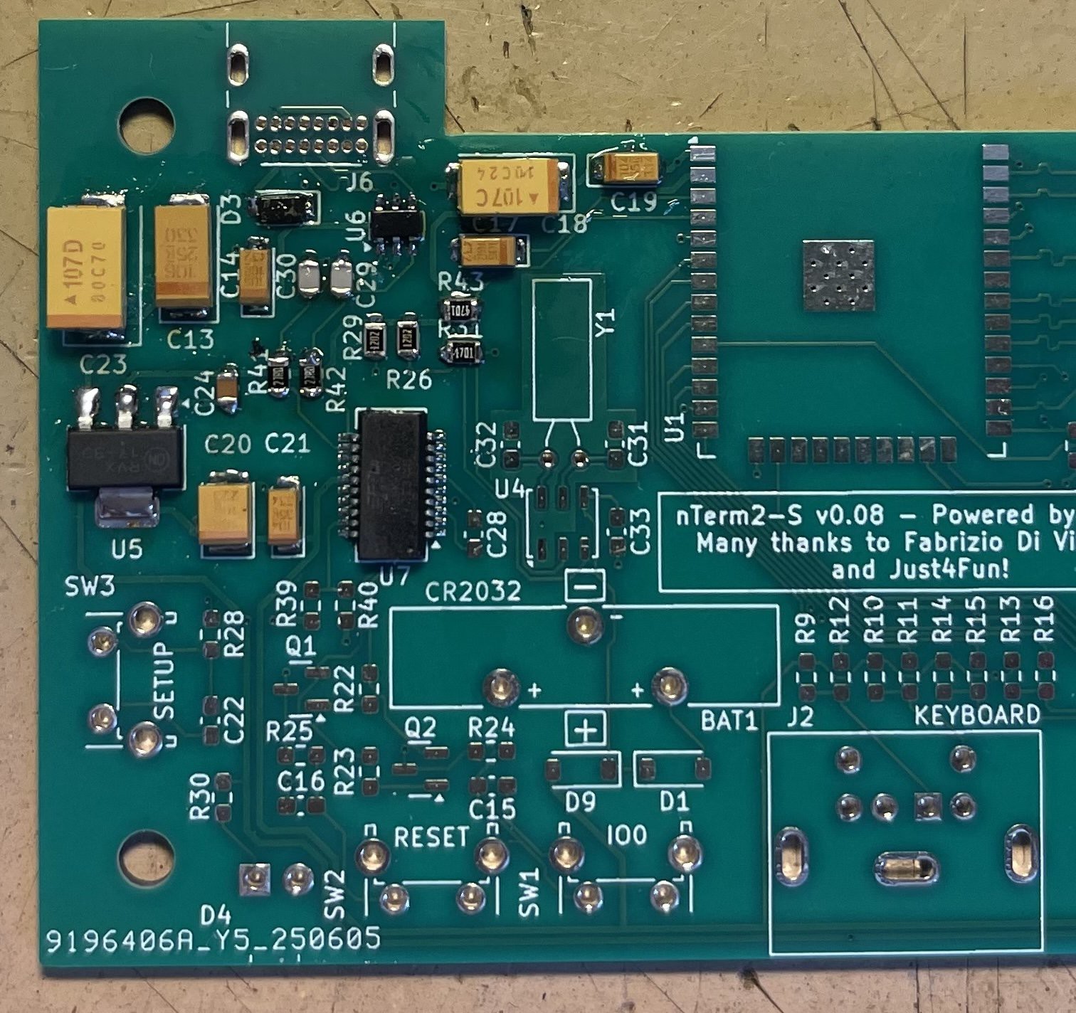
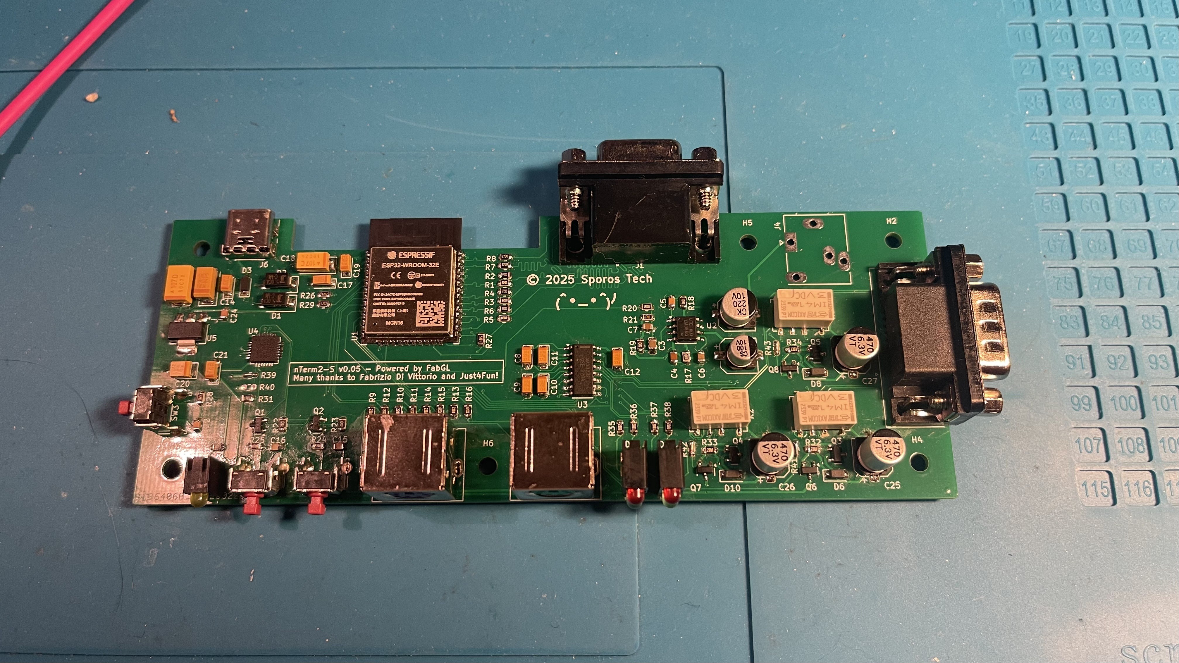
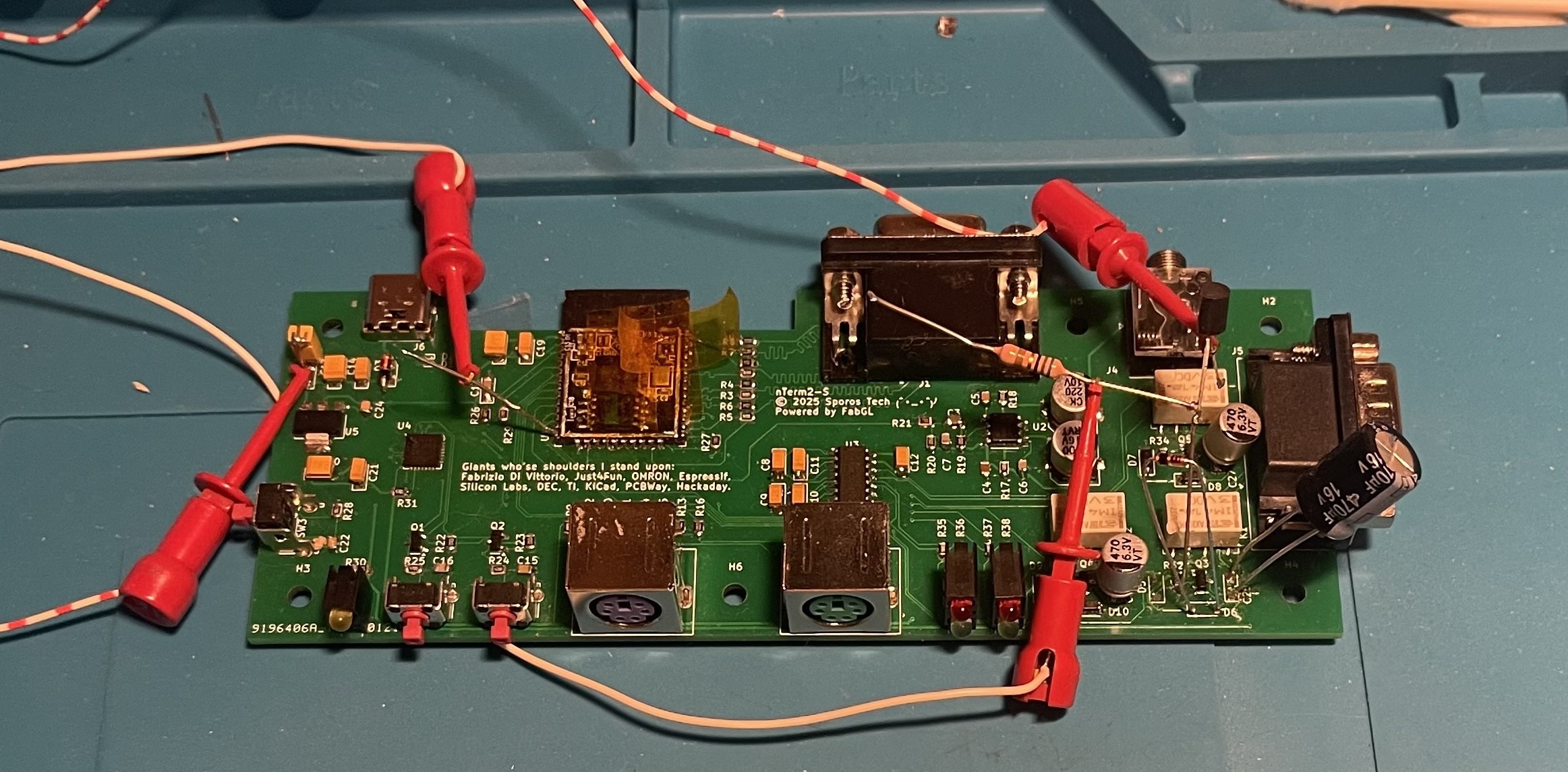
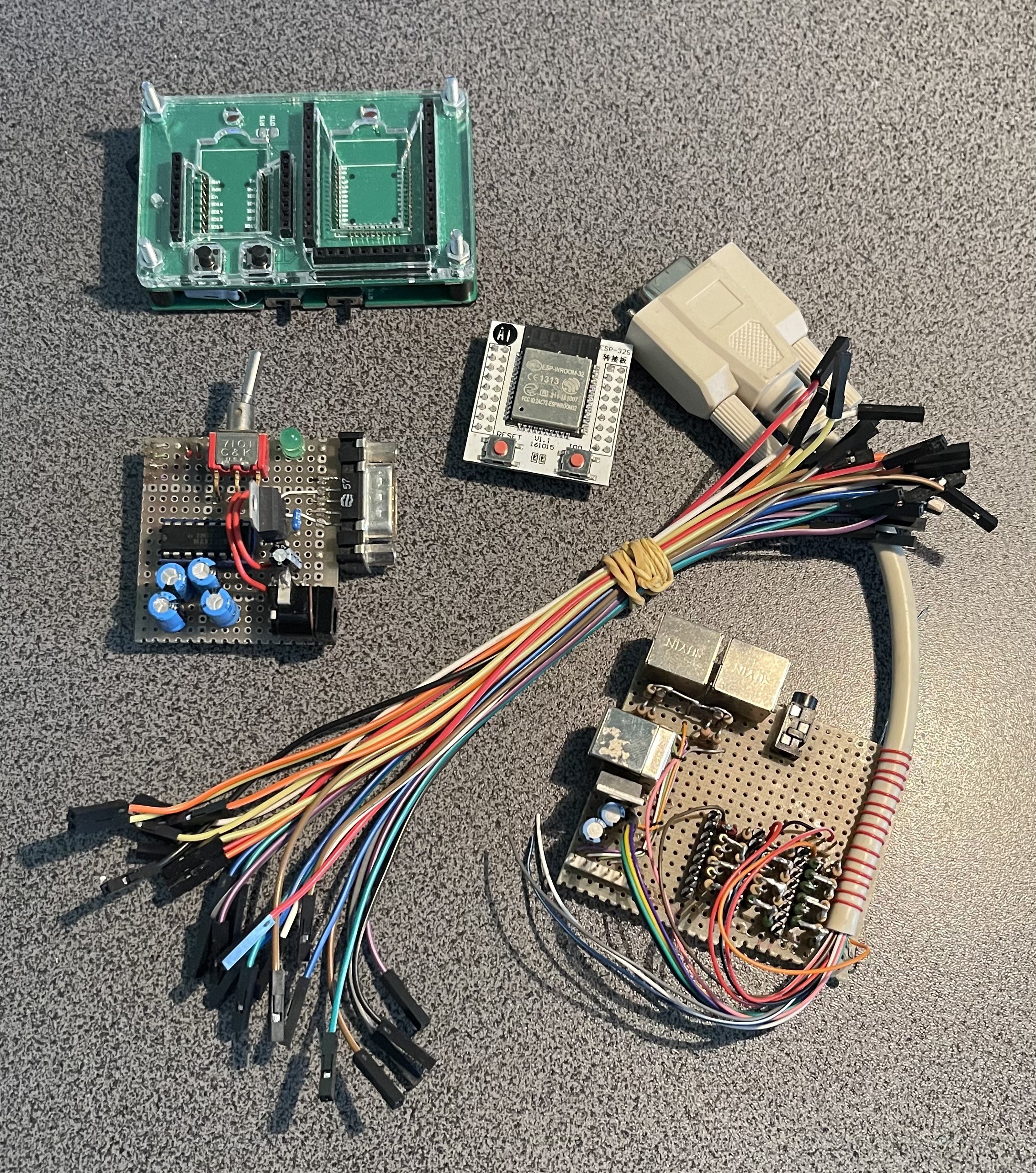
So I decided to make my own board based off the FabGL Serial Terminal board and the uTerm2-S:

The nTerm2-S!

  • Conclusions

    Retep V04/30/2026 at 18:25 0 comments

    Now, of course I have some regrets.

    The first one is that I didn't use an ESP32 WROVER. That has an extra 8MB PSRAM, which can help tremendously in freeing up some memory. SporosTerm has so few memory free that I have to bend over backwards here and there to make it all work. Having the extra PSRAM might have made my software developments easier. And it would also have enabled the nTerm2-S to run FabGL's dos computer emulator. :)

    The second regret is that I actually think that I had better used the 4066 or equivalent, instead of the relays. It's less robust than a relay, but it would have used a lot less board space. And it would have been cheaper too.

    The third regret is that the ESP32 does not have a full UART. It actually really only implements RxD/TxD and RTS/CTS flow control in hardware. My switcheroo circuit makes it possible to connect DSR/DTR to the RTS/CTS of the ESP32 and more or less provide hardware DSR/DTR handshaking that way (possible because the ESP32 has large buffers and is quite fast). It works, but RS-232 is an old standard, and many old devices have some weird combination of handshaking, and I would like to support that somehow.

    A fourth regret (but not so big) is the VGA connection. It would be nice to have an HDMI port instead of VGA.

    A fifth and final regret is the cost. The cost of components alone is about 45 euro all-in, at low volumes. If you buy smart or higher volume, you probably can get down to 35 euro or even less. I think that it's possible to do it cheaper than that and still have better features.

    For now, I'm tweaking the software, and will continue doing that for a while.

  • v0.12 unfortunately

    Retep V04/30/2026 at 16:58 0 comments

    The n00b mistake that I had made reared its ugly head when I plugged in my nTerm2-S v0.11 into my macbook directly, using a USB-C to USB-C cable. Up til then, I had always connected through an old USB 2.0 hub, figuring that if I made a mistake, it was better to let the USB hub go up in smoke than a USB-C port on my expensive MacBook. This is good practice that anyone should follow.

    But it has a caveat...

    USB 2.0 happily always provides the device with 500mA of power, regardless of anything. So if you use a USB 2.0 hub, with a USB 2.0 to USB-C cable, and plug in your USB device, it works great.

    However, USB-C wants to negotiate first about how much power it will give you. And if your device doesn't negotiate, USB-C just doesn't give it power. Simple as that.

    The power negotiation of USB-C (USB-C PD) is a bit involved, but at the minimum the device needs to negotiate its power role. In the case of the nTerm2-S, its role is a power sink (it needs power, doesn't deliver it), and that role is negotiated by putting two 5K1 pulldown resistors on the CC1 and CC2 connections of the USB-C connector. And guess what I forgot...?

    Hacking a few resistors onto the V0.11 board confirmed that it was indeed the problem.

    It's especially unfortunate because the space around the USB-C port was already quite cramped, and I just couldn't find the space for the resistors. Of course I could have actually placed them almost anywhere on the board, because they are passive. But that goes against aesthetics. So I took the time to refactor almost the whole USB and power area. And to be honest, I was quite happy with it because it now looks more neat.

    Spot the differences.

    And there we are. It's now 2 months later, and I have still not found any reason for any new updates to the hardware. And that means that I am done with the hardware.

  • v0.11

    Retep V04/30/2026 at 16:09 0 comments

    v0.08 had everything working to such extent that I could continue developing the software. Many, many hours have gone into the software, even though it was based on a library that already existed. So I postponed making a new version until I got much further into the software.

    But in the mean time, I was updating the design. v0.09 was already there, fixing some missing thermal reliefs. v0.10 came and went, which fixed a few small details, including the mentioned capacitor. v0.11 added a pin header for connecting a volume pot, and had some improvements in the routing.

    I ordered PCBs, which arrived after some time. I actually made videos of how I soldered it together, but due to lack of time and lack of experience with video editing, I have not processed them into a nice video yet.

    But here is the end-result!

    Of course, the story does not end here. Because I am a n00b, and I expect that a few of the people who have had a look at any of the versions I made, other than V0.12, will have spotted my mistake. :)

  • v0.08

    Retep V04/30/2026 at 15:50 0 comments

    The v0.5 was actually such a success that instead of tearing the whole project down with my switch to the FT231, I decided to clone the project into a new Github repository and name it nTerm2-S-FT231. I'm not sure that was actually the best thing to do, but here we are.

    While testing v0.5, another thing had started to annoy me. I had started to write the software, and at some point got the status bar to work. And I was showing the date and time on the status bar. But every time I cycled the power, I had to set the clock again. Not ideal, so I started looking for an RTC chip. Now, I had all of the GPIOs in use, except one. So if I would want to add an RTC without making changes to the GPIO or surrounding circuitry, I had to find something that used one wire. 1-wire! I shopped around on Dallas's website and found the DS417. Not really an RTC, but a 64-bit counter that increases the count with 1 every second. Sounds like Unix time_t to me, so perfect. Cobbled a prototype together on my v0.5 board, and it worked first time.

    Next up was removing the CP2102 from the design and putting the FT231 in. That was a major undertaking, but went well. I also got smart on the TVS diodes and used a chip that had everything inside it to protect the USB lines.

    After I got that done, it was time for the RTC. The RTC's clock circuit had quite some requirements for the PCB design. Especially large copper fills around the crystal.

    At the last moment I added solder bridges to the circuit, so that people could decide what they want to populate or not. Bridges for bypassing the amplifier and bridges for bypassing the relay circuits.

    The rest of the changes were again a few wrong footprints. A few commits later, I arrived at v0.08, and sent everything off to JLCPCB again.

    The next day I was already sorry that I had jumped that gun, and had a v0.09. But there you go, v0.08 was the next version that got life breathed into it. Here's a nice close-up pic of the FT231 and the RTC clock circuit (not populated yet).

    Now, I want to point your attention to capacitor C19, at the top right. See how its orientation is different from all the other capacitors? That's a recipe for disaster, because for sure there will be people (including myself) who will solder it the wrong way around. This is a major showstopper, unacceptable and cannot be released this way.

    But other than that, this release was great, it worked flawlessly, the clock worked, all the footprints were finally right. Just that pesky capacitor that I should have rotated. Great success!

    Or, once again: so I thought.

  • v0.05

    Retep V04/30/2026 at 15:18 0 comments

    Version 0.05 was to be the fix-all version, my final version! Of course...

    After I had ironed out the problems with the relays, there was one important thing that I had neglected and should fix: protection diodes on the USB port. So I set out to add them.

    I found some nice diodes initially, but the were ti-ny... Meant for mobile phones and industrial manufacturing. And I thought that nobody was going to be able to hand-solder those. So I went out to search for bigger ones and used those.

    Next was that I, of course, had a few components with the wrong footprint, mostly the large tantalum capacitors, but also the relays.

    And after some puzzling, I got to v0.05. Ordered PCBs and started soldering.

    Did I mention that in v0.01 soldering the CP2102 was hell? Well, in v0.05 it was worse for some reason (probably time of day, or my coffee intake). I got it soldered down properly, but I decided that I did not want to go through that again, and did not wish anyone else to have to go through it. This was the final straw, the next version had to have a different USB chip.

    So sad that Silicon Labs decided not to produce a SSOP version of the chip. The QFN-28 version has 10 N/C pins, meaning that only 18 pins are used and it could fit in a SSOP-18 package.

    Well, after soldering I hit my first big problem: no USB. The device was not recognized at all. I doublechecked all connections, doublechecked my schematics, the PCB design, all seemed fine. So the only thing left to be suspicious about were the TVS diodes. I removed them, and there it was: device recognized and doing its stuff.

    I went on the forum to ask what I had done wrong. And well, 54 minutes later I had the answer: the diodes that I had chosen because they were of easily solderable size, actually had way too high a capacity (500pF) and were seriously impacting the USB signal. I should have used diodes with a capacity closer to 0.5pF. So that was also a "back to the old drawing board".

    For the rest: everything worked great, I was soo close now! I thought...

  • v0.01

    Retep V04/30/2026 at 13:50 0 comments

    With my requirements and stretch goals set out, I fired up Kicad and started to pull in components until I had basically more or less replicated a mix between the FabGL Serial Terminal and the uTerm2-S. However, I wanted to have a way of switching the serial connection between normal and null-modem.

    I found that real crossbar ICs that could handle 12V were extremely expensive. I considered the venerable 4066 analog switch, and other analog switches. But then stumbled on a post that was talking about a circuit controlling a bistable relay with only one GPIO port. That was interesting enough for me to try out, and after buying some relays and prototyping, I got it working quite stable within parameters. The relays were surprisingly cheap, and I was up for experimenting. So I chose to use relays.

    But relays use a lot of current when they are being powered. So I chose to use latching relays. But that had yet another problem. The small ones are single-coil latching relays and are set one way by applying a pules with a specific polarity, while they are set the other way by applying a similar pulse, but with reverse polarity. That requires two GPIO pins, and I did not have enough.

    Another option would be to use a circuit built around two comparators, and use one GPIO pin in tristate mode.

    But then I stumbled upon a really simple circuit, once patented by Omron, that could do the same with one GPIO pin, but not using tristate mode, built around a transistor, two diodes, a resistor and a large capacitor. It can be seen here on page 12, section 2.2.24.

    I started experimenting with the circuit on the breadboard, and it worked fine. I measured currents, and it all seemed within specs of the ESP32's GPIO port, so I went for it.

    I designed the PCB fully, and sent it off to JLCPCB for the ridiculously low price of €11.01.

    After a few days the boards arrived, and I started soldering! Everything went smooth, except for soldering that pesky CP2102 . USB worked, I could program the firmware, got VGA out, keyboard and mouse were working, and after programming some lines to switch the relays... No clicks, no switching.

    :(

    So that led to taking out the oscilloscope and trying to find out what was the problem. That is described in the Github entry of the nTerm2-S, and I would refer you to there if it interests you.

    After a while, my beautiful board turned into a Frankenstein. Not helped by the fact that I only had ESP32s that were soldered onto a carrier board, decided to desolder one, ripped of an important pad, and had to perform microsurgery to solder a wire onto it :D.

    In any case, a few more redesign steps had to be taken, and at some point I reached v0.05 (don't ask me about the version numbering, I just chose this without much thought ;)).

  • First prototype

    Retep V04/30/2026 at 11:48 0 comments

    Everything began with the first prototype I made. In the previous post I mentioned that many of my projects stranded in the phase where everything was held together with strings. Well, this prototype is one of those. As far as 'being held together with strings', while still doing its work, is something to be proud of, I am extremely proud of this one! Let me show you. ;)

    The parts.

    The result. Working!

    That it was actually speaking with my SYM-1 was motivating enough to dive headlong into the project.

    I also want to note that I had started out writing a few blog posts about the process, and hope they will be somewhat entertaining for you. :)

    To be honest, in the - On Terminals - blog post I mention 13 requirements and 3 stretch goals. ;)

  • Introduction

    Retep V04/30/2026 at 11:39 0 comments

    As the project is already close to being finished, and I basically used Github's README.md to record my progress, I am writing this page on Hackaday.io as a way to 'release' the device, and as a way to get feedback on it.

    This was a project that I did for myself, to prove I could do it and to learn, and so I did.

    I set out with a list of requirements, which I carefully curated. And I was determined to implement no less, but also no more of those requirements. The reason being that I have many unfinished projects, and many of those projects are unfinished because I set either unrealistic requirements, or ended up spending much time on feature creep instead of taking time to finish off something that was well rounded and not tied together with strings.

    • The nTerm2-S would be basically using Fabrizio's FabGL library, and should be fully compatible with it. The objective being to run Fabrizio's excellent ANSI terminal example.
    • It should be small, made with SMD components, and still be hand-solderable. The objective being to learn to use Kicad and make PCBs through JLCPCB or the like.
    • It should feature a real RS-232/V24 port, meaning that it should be able to communicate RS-232 with +/-12V (or so).
    • It should feature an on-board amplifier so I could simply connect a speaker.
    • It should feature a way to, in software, switch between normal communications and null-modem.

    I more or less succeeded in all of that, and come to a rounded, finished, project, which I am proud of. :)

    But still, I had missed one important requirement that I want to name here.

    • It should have an on-board RTC with battery backup.

    In this blog, I'll highlight a few of the most interesting challenges I had, in the hopes that it is a bit educational. Also, I am thinking of making a new version with more or less the same requirements, but using HDMI. And I'd really like to hear some feedback too.

    You can read all the details (really, there are a lot, I like to write ;)) of my development process on the corresponding Github pages.

    One thing I want to clarify up front is why there are 2 versions of nTerm2-S: nTerm2-S and nTerm2-S-FT231.

    I started out designing the nTerm2-S using a CP2102 USB to Serial bridge IC. It is a great IC, supported out-of-the-box by all major Operating Systems without having to install any drivers. I love it, and it was working great in the nTerm2-S. However... When I made my first prototype, I found that it's really hard to hand-solder reliably. I had to resort to hot air and a lot of fiddling to get it properly soldered down. I thought it might be me, having a bit of shaky hands. But with my second prototype it was all the same misery. So after long deliberation, I decided to switch to a different USB to Serial bridge. After careful looking around, I found the FT231, basically archived the nTerm2-S with CP2102, and made a new Github project nTerm2-S-FT231. And that is the version that I brought to completion.

View all 8 project logs

Enjoy this project?

Share

Discussions

Similar Projects

Does this project spark your interest?

Become a member to follow this project and never miss any updates