Close
0%
0%

Excalibur 64 - A new build

Or should that be 'A new hope'?

Similar projects worth following
As mentioned in my Excalibur 64 recreation project log, I now have a real Excalibur 64 mainboard and keyboard PCB in hand! These are on loan, and the owner would like them returned fully populated.
This is actually a relief—if I owned them myself, I’d face a real moral dilemma: do I leave them untouched as a piece of history, or build them up? Now, I get to enjoy the build without the guilt!
This board is the final version (Rev 5, Issue 1), so most earlier bugs have been addressed. My plan is to use it to verify my recreation; my current schematics are for Rev 4 and contain several known (and a few newly discovered) errors. Once the detective work is done, I’m going to populate this board like it’s 1983!

Excalibur 64 Recreation: https://hackaday.io/project/205460-excalibur-64-the-recreation

Jobs to do:

TaskStatus
1Do a hi-res scan of both sides of the PCBsDone
2Update a copy of the Kicad schematic used for the recreation projectDoing
3Import components to Kicad PCB place and then spend many hours tracing the tracks from the scan Doing
4After DRC checks create Gerbers for PCB manufactureNot Yet
5Start populating the original board *.Doing
6When we get the PCBs back build one and then take over the world.Not Yet

* Original plan is to wait until a PCB was manufactured to compare closely with the original board but the PCB tracing is going to take ages so took the risk and started populating the original PCB while doing the Kicad work.

1. Scans

This wasn't too hard. Had to do some stitching but came out alright.

2. Update Kicad schematics

My recreation uses SRAM instead of DRAM and replaces the two EPROMs with a single FLASH so need to change these so we can layout the board. There is also a PROM ( 6331-1) that is used for the Colour Look Up Table (CLUT). These are hard to come by so I'm looking at using a ATF22v10 which as a different pinout and pin count. So not sure what to do here. Keep the board the same and make an adaptor or commit sacrilege and change the board design??!! Any feedback welcome here. Same problem with the audio out. The output is just a BC548 which gets awfully hot. The user group newsletters has as a fix by using a bigger transistor and a 1w resistor. Same dilemma but in the case our ancient forefathers fixed this, so is it cannon to redesign the board, or bodge it after?

3. Import Components

 This is just importing the components onto the board. The components will be laid out then manually tracing the tracks, using the scanned board as a guide. Haven't done this before but should be too hard. I hope 😉

4. DRC Checks

Yes do the usual Design Rules Checks. This is a big board and don't want to find out after they are manufactured that there is something wrong!

5. Populate the original board

As the title says, start on the real board. I have all the components so should be good. The original used 74LS and NMOS ICs. I only have  CMOS versions the Z80, 8523, MC6845 etc... so will have to use 74HCT me thinks. See how we go but hopefully the board will work straight out of the box. Will be using the original ROM images.

Keyboard may be an issue as the key footprint is not your standard footprint. But have already made some keyboard PCBs with the Cherry MX footprint. Need to research that one a bit more.

6. Populate the new board

As above, I hope. Then use it to play a game of Thermal Nuclear War. What could go wrong?
excalibur_64_construction_manual.pdf

This is the original construction manual. Could still be useful?

Adobe Portable Document Format - 3.07 MB - 05/01/2026 at 06:39

Preview

  • Got some new ROMS!

    Dave06/30/2026 at 04:30 0 comments

    Managed to get a different version on ROMs for the board. Luckily, I did as up and till now the only version I had was for the Hi-Res board which unfortunately I don't have so if use it here it never would have worked.

    For the build looking like I'll go 'all the way' with TTL ICs. There is some tricky timing happening so will be good to keep everything the way our founders intended then mess about with new technology

    Still looking for that elusive Hi-Res card and 512k expansion. Here is the Hi-Res! wanted dead or alive. With install instructions please 😁

  • Clock and Reset circuit done, almost.

    Dave06/29/2026 at 01:46 0 comments

    Ok the clock is running nicely, even with-it being way over on the other side of the board!! Not all ICs are in yet but I'm assuming I'm going to have issues with noise once the board gets busy.

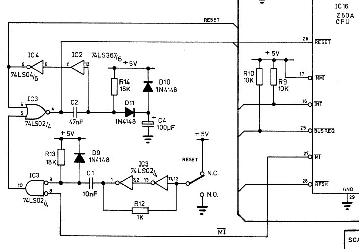
    Have also installed the reset circuit as per below with a CMOS Z80 the circuit doesn't work. I think it is due to the mix of TTL and CMOS. The reset circuit using purely 74LS caused the /RESET line to stay low. I replaced the 74LS02 with a 74HCT02 and it fixed the /RESET staying low but the reset button doesn't work. Need further investigation but probably need to replace IC2 with a 74HCT as well. Need to scratch around to see if I have one else I guess I could put a 1k pull up on the /RESET to ensure there is +5v on the line.

    Also getting some nasty spikes on the data and address lines, this CMOS/TTL mix is going to be an ongoing problem me thinks. 

  • Side Quest

    Dave06/10/2026 at 03:16 0 comments

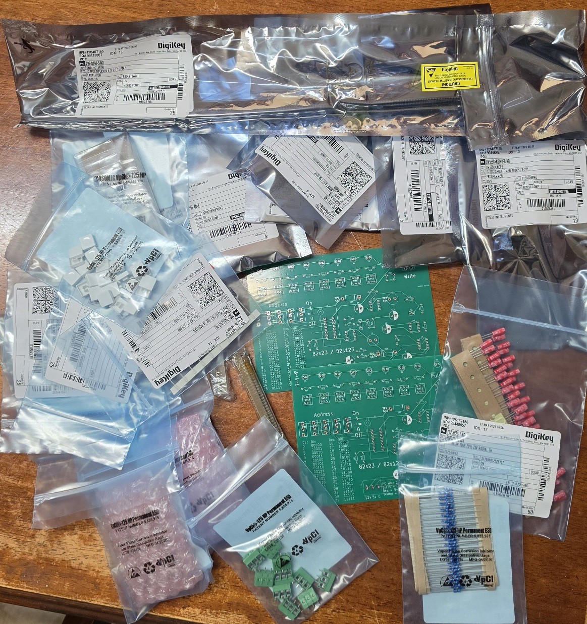
    The 6331-1 PROM used for the colour palette is not very new. So are a bit expensive and need a special programmer. The average programmer, like the TL-866, don't supply the right programming voltage for it. So being bipolar it needs something more specific and this is it. A manual programmer where you have to flick switches for the address then load the value for that address. This board is very similar to what was published in the early eighties by ETI and probably a lot of other magazines as well. The PROMs are one time programmable so need to take it nice a slow.

    Have all the bits so will be building it like it's 1984.

    Quick specs of the 6331-1

    • Memory Capacity: 256 bits, organised as 32 words × 8 bits.
    • Package Type: Narrow 16-pin Dual In-line Package (DIP).
    • Technology: Schottky Bipolar architecture using Nickel-Chromium (NiCr) fuses.
    • Speed Designation: The -1 suffix indicates a high-speed variant of the standard 6331 chip
    • Equivalents:  82S23 or 82S123 from Fairchild, 74S188 or 74S288 from TI , 74S188 or 74S288 from Harris

  • It's all a bit passive

    Dave06/08/2026 at 10:21 0 comments

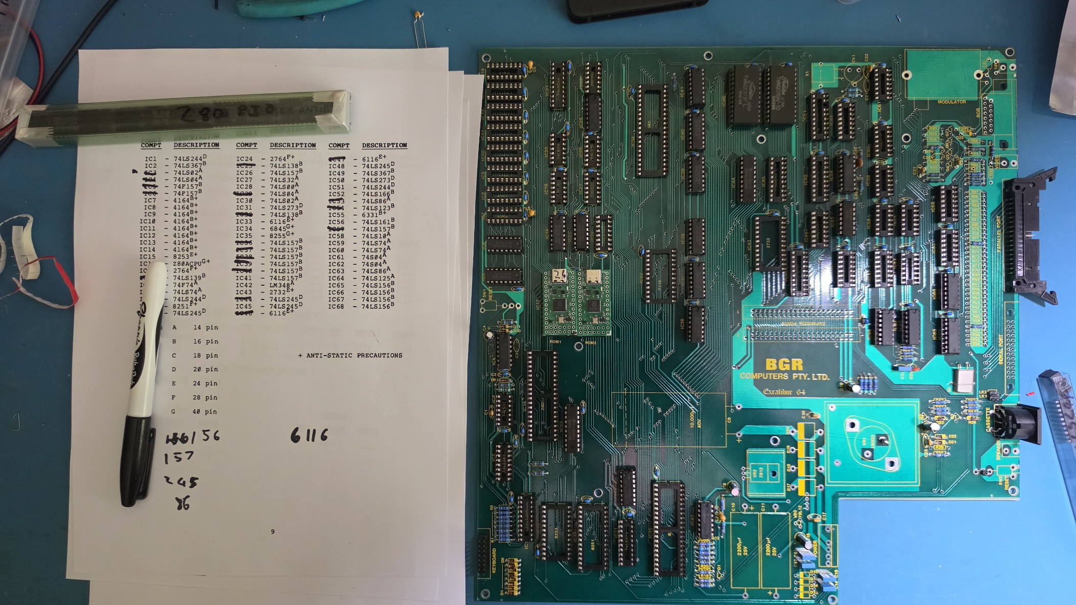
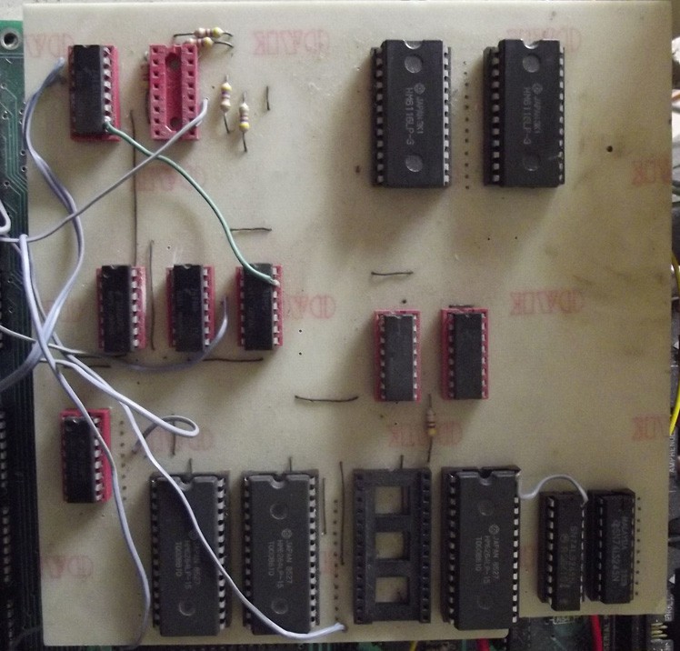
    So, nearly all the passive components are in. Missing some ceramic caps but rough enough for now. Unfortunately I'm missing some key 74LSxx ICs. Installed what I had and the clock circuit works fine. Going to use the OneROM for this build, hope they are ok with the 74LS? If not I can still use 27128 and 2764 EPROMs. Just need to order them from Unicorn or somewhere like that. This isn't a development board so maybe OneROMs are an overkill?

    One interesting thing with the EPROMs is the that one of the images is 16Kb and the other is 8kb. Which equates to using a 27128 and a 2764. This matches the memory map I have from a forum ROM1 as $0000-$3FFF and ROM2 $2000-$3FFF, the region from $0000-$1FFF is always active when the /ROM switch is selected. Which ROM appears at $2000-$3FFF (either rom2 or the second half of rom1) is determined by bit 5 of the control register at port $70. This isn't mentioned in the documentation or schematics, so presumably these are later version ROMs from the original?

    The schematic shows them as both 2764 and A13 is not connected. I know a couple of people who worked on this computer and developed expansion boards back in the day. I simply call them 'the oracles'. Hopefully one of them can explain how it works. I got away with in my recreation as I just used on big Flash ROM. This is where having a pre-build one would be handy 😒

    Oh well, poor me, need to order even more bits. On the plus side, the programmer for the 6331-1 has arrived, so I will be busy building that and programming a couple of one-time programmable ICs. What could go wrong? 😊

    Footnote: I'm using the original construction manual for the build (on the left) and has proven to be quite handy.

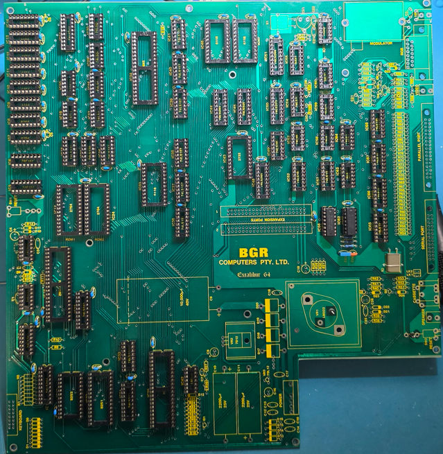
  • Sockets Done!

    Dave05/31/2026 at 21:39 0 comments

    Nothing amazing to report but all the sockets are done. And, just because I had it I, installed a 74AHCU04 for the oscillator circuit and works fine. But there is some noise so may have to fiddle with the resistor values. But still want to keep it original so will try a 74LS. If it worse then I will need to accept not all of it can be original. Need a clean stable clock. The CPU is on the other side of the board.

    Now onto the resistors and caps. Notice on the right? So many resistors and just to make it fun they are nearly all different values ... they are for the D to A used by the composite video out. 

  • First Contact

    Dave05/30/2026 at 07:49 6 comments

    Ok I but my big boy pants on and actually made a start on the Excalibur 64 Original build. My initial idea was to build it stages. Starting with the oscillator, then CPU, ROM/RAM, then move further out to the I/O and finally video.

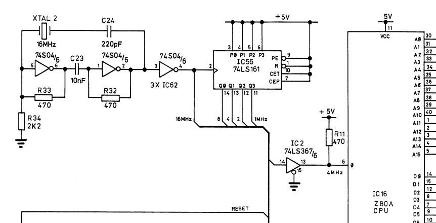
    But I didn't have quite the right ICs for the oscillator. It needed a 74S04 for amplification and phase control and a 74LS161 to divide the 16Mhz crystal. Only had a 74LS04 and a 74HCT161. Discovered these are no good. The oscillator circuit is a  two-inverter series-resonant crystal oscillator. The two inverters provide a  0 degree phase shift. The problem is the 74LS series has much less drive capability compared to the 74S series. I could muck about with the 470 resistors to reduce the load but I want to keep it as original as possible. So will have to leave the oscillator for the next bits order. So figured might as well start installing all the IC sockets. Which is quite therapeutic.

                         This the two-inverter series-resonant crystal oscillator

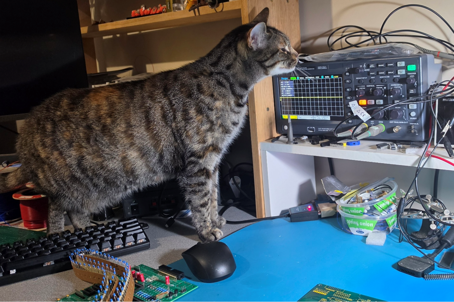
                    I thought it best to conduct a cat scan before declaring I had the wrong ICs

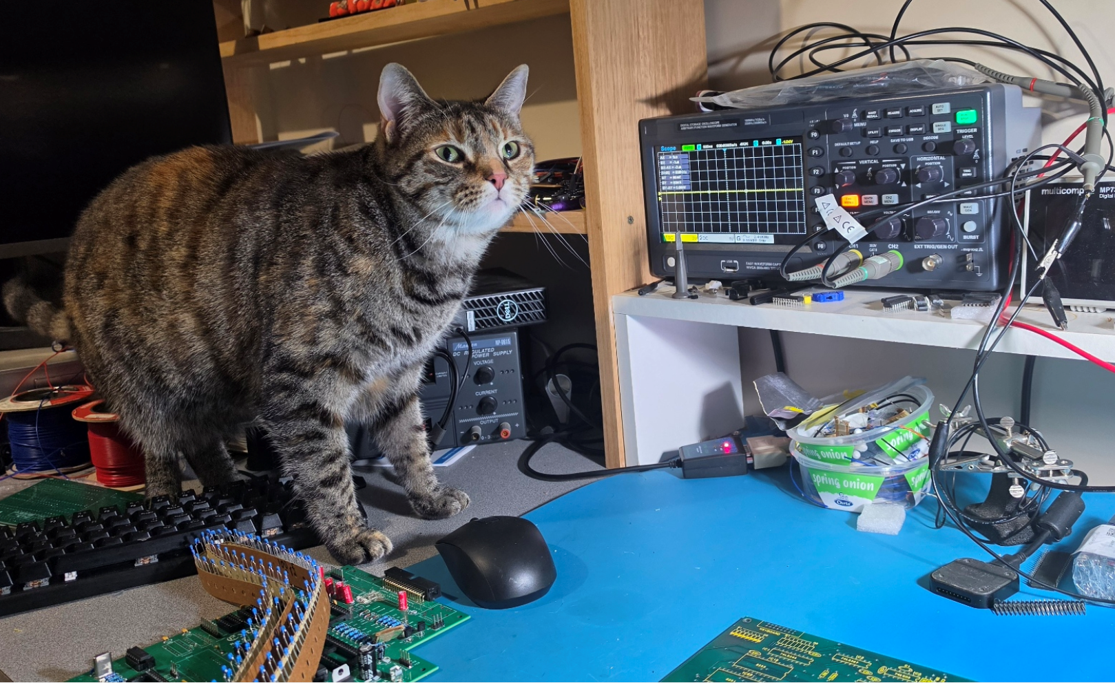
                       Reading her facial expression it's confirmed 😒 need the right ICs

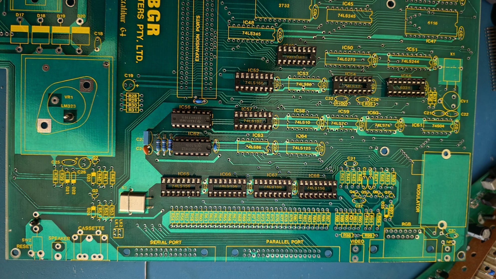
                        And the progress so far - not too exciting but will be!!

View all 6 project logs

  • 1
    excalibur_64_construction_manual

    Added the original construction manual to the files

View all instructions

Enjoy this project?

Share

Discussions

Similar Projects

Does this project spark your interest?

Become a member to follow this project and never miss any updates