Close
0%
0%

Applix 1616 build

The rebirth of an kit computer

Similar projects worth following
208 views
0 followers
The Applix 1616 was a kit computer powered by a Motorola 68000 CPU. It was released in 1986 first seen in the magazine ETI. It ran a custom multitasking multiuser operating system resident in ROM. Compared to other computers of the time this was very impressive. It launched with 512KB of RAM (expandable to 4MB), and the OS eventually gained preemptive multitasking, multiple user support, and pipes. It's a shame it didn't take off. But hopefully this issue can be remedied with a faithful recreation.

So this project attempts to build one using the original ROMs. But I'm taking no credit for the PCB that was done by Forthnutter ( see below ). He has a real one and faithfully recreated the PCB. This project is essentially a build log based off his PCB.

This is the original project that this build is based
https://hackaday.io/project/192942-applix-1616

And here is some great documentation
https://hackaday.io/project/182024-applix-1616-documentation

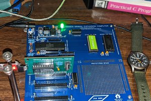
This is a build of a Applix 1616. A lot of the parts are available including the obsolete parts that can be found on may sites as new old stock.  As mentioned in the the intro the PCB was done by others I just sent off the gerbers to JLCPCB and 5 boards came back. The PCB is pretty big 394 mm x 210 mm . Lots of connectors like a Centronics port, 2x serial ports, 4x80pin expansion ports audio and 2 analogue joystick ports which is quite nice. Looking forward to playing some games on it.

Quick specs

=====================================================

CPU:                     68000 16/32 bit running at 7.5MHz

Memory:               512kb DRAM and expandable to 4.5Mb on board

ROM:                     up to 128kb on board

Graphics:              320x200 16 colours, 640x200 any four of 16 colours. 

Audio:                   Stereo sound with onboard amplifier

Storage:                Cassette port and RAM disk support software in ROM

Expansion ports: 4x80-pin expansion ports with all 68000 signals 

                               Dual serial RS232

                               Dual  Analogue two button joysticks

                              General purpose analogue and digital I/O
  • 1 × MC68000P Microprocessors, Microcontrollers, DSPs / Microprocessors (MPUs)
  • 1 × 65C22S6 Versatile Interface Adapter (VIA)
  • 1 × Z85C3010 SCC Serial Interface Controller
  • 1 × M6845 CRTC Controller

  • Playing with my PALs

    Dave2 days ago 0 comments

    Not having much luck with my new PALs. Getting the right signals out for the clock divisors, RAS and LPULSE are ok butt CASL and CASU are not. Need to check the basics like the HALT signal as well as the BR (Bus Request) and BGACK (Bus Grant Acknowledge). Then the interrupt lines and make sure they are not low for some reason. So a bit of work to understand what's going on.

    Gee I hope this thing can play some good games 😋

  • My PALs have arrived!!

    Dave3 days ago 0 comments

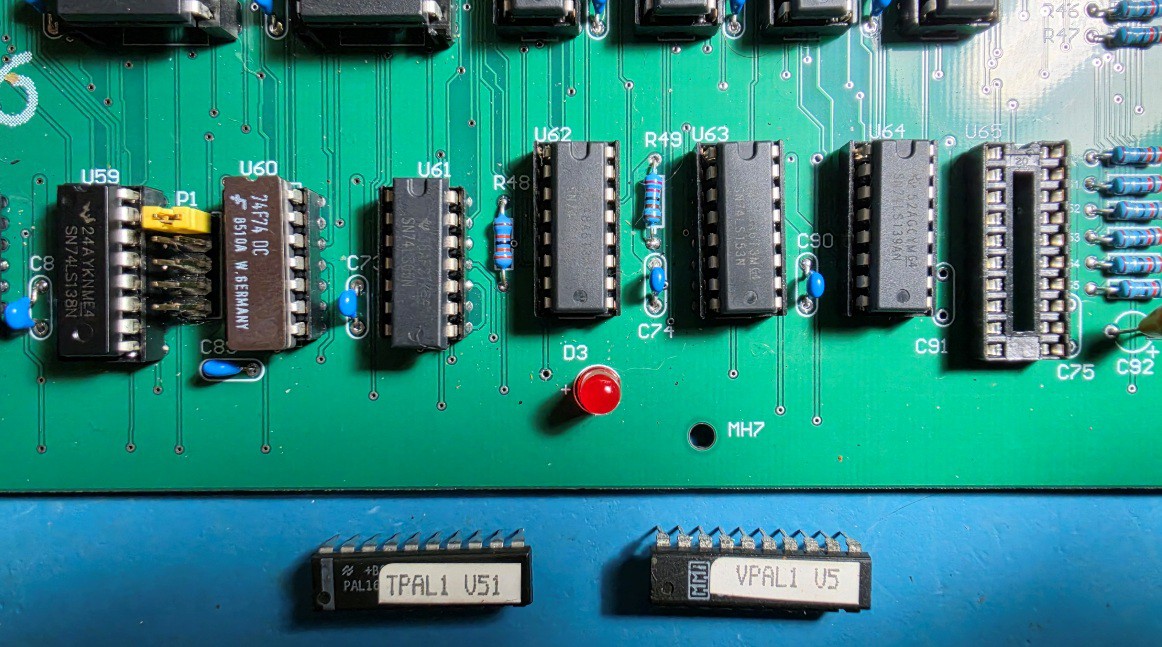
    A fellow Hackster gave me the all important Timing and Video PALs for the board. These are quite rare as they can't be read with a simple EPROM programmer so not easily copied. The original program for these has been lost to time so the only way to create new ones is to reverse engineer real ones. While not too difficult it does involve inputting various conditions and see what pops out. The Timing PAL manages the timing for the DRAM refresh and needs to do it in sync with the 6845 CRTC controller. So can be a bit tricky.

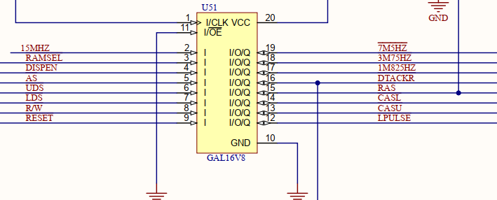
    But anyway I stuck them in and no joy the clock divisor works ( pins 17-19 ) and LPULSE (12) but DTACKR and RAS, CASL and CASU all stay high. Haven't had a proper look yet. Still need to do some tracing ( its most likely me not the board) may be as simple as something in the reset circuit. I'm not forgetting about the VPAL but without the timing the VPAL won't be doing much.

    I  have till Friday to sort it out as I promised to lend them to someone in the UK who is lot smarter than be and will be about to sus it out in a jiffy. 

    And this is the pinout for the TPAL.

  • Made a start

    Dave05/12/2026 at 23:04 0 comments

    Have made a start on the board. Was only going to do the minimum to work on the Timing PAL (TPAL) programming. But was in the zone so kept going until I ran out of IC sockets and .1uf Caps. Another order for DigiKey 🫤

    The EPROMs ( sorry FLASH Memory) are programmed with the original code. As for the TPAL I managed to work out the clock divisors, but the TPAL does a lot more than that. It uses a 3-bit synchronous counter driven by 30 MHz and 15 MHz clock inputs to generate critical DRAM timing signals, such as /RAS, /CASL, /CASU, and ROW/COL. Not something I can work out easily so will have to wait for people smarter than me to work that one out.  

    Till then I'll be optimistic and continue soldering bits in. Have a good de-soldering gun as back up. 😋

View all 3 project logs

Enjoy this project?

Share

Discussions

Similar Projects

Does this project spark your interest?

Become a member to follow this project and never miss any updates