 Raushan Kumar

The project is built with the AP33772S USB-C PD sink controller, an ESP32 microcontroller, and an INA226 power monitor. Together, these components allow PowerPD to negotiate PD/PPS voltages, measure voltage and current in real time, and provide a simple user interface through an OLED display and rotary encoder.
HARDWARE
Main Components
- ESP32-WROOM-32E Module
- AP33772S USB-C PD Sink Controller
- INA226 Voltage/Current Monitor
- MP1584 Buck Converter
- AP2204K 3.3V Regulator
- USB Type-C Connector
- 5 mΩ Current Sense Resistor
- MOSFET Output Switch
- 1.3-inch SH1106 OLED Display
- Rotary Encoder
- Push Buttons
- Status LEDs
- Assorted resistors, capacitors, diodes, and other passive components
PCB DESIGN
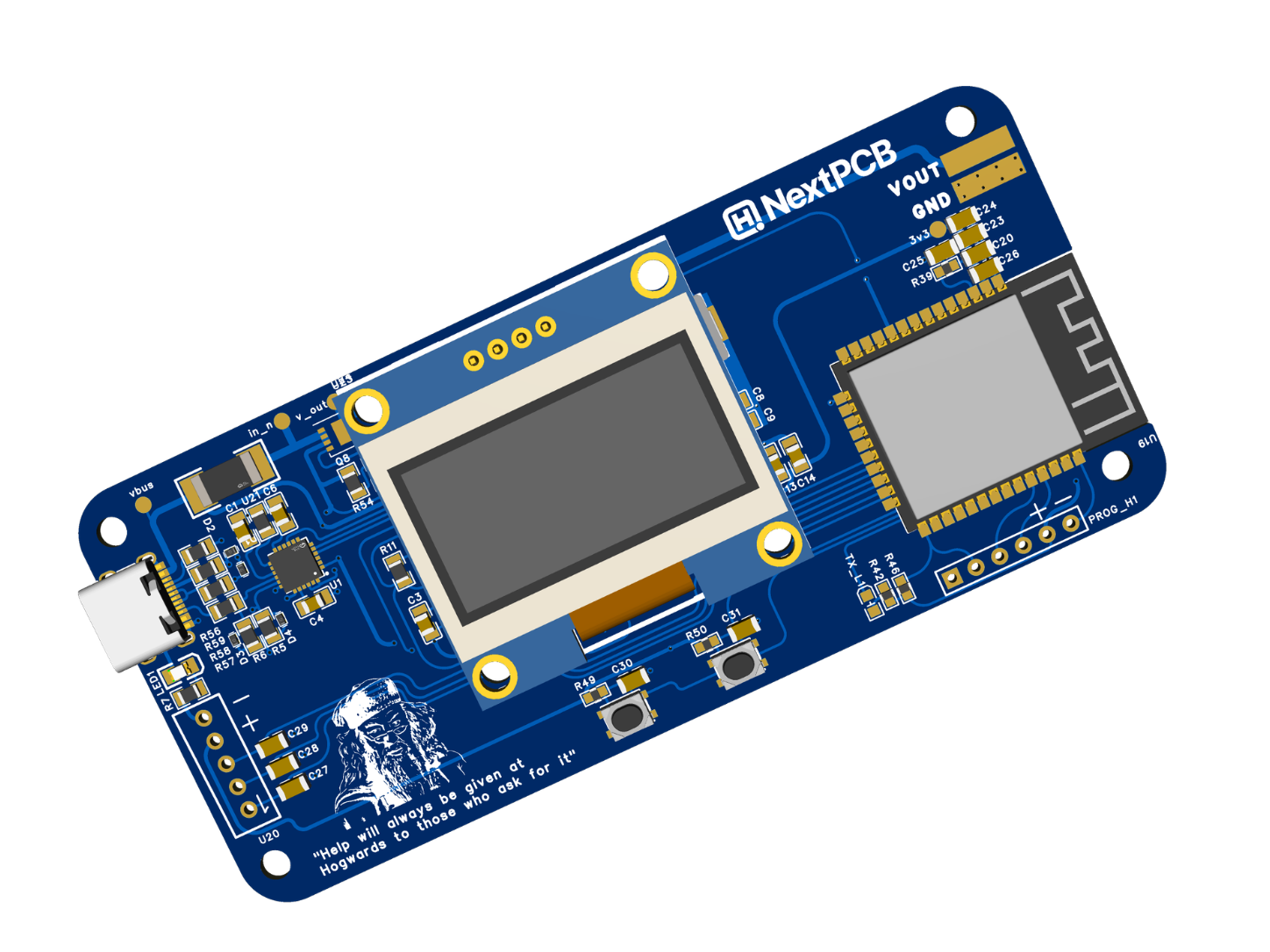
My friend Rabindra designed the PowerPD PCB in EasyEDA.
The AP33772S USB-C PD controller is placed close to the USB Type-C connector to keep the CC traces short and clean. The INA226 is positioned right next to the 5 mΩ shunt resistor so it can use proper Kelvin sensing for accurate current measurement.
The AP33772S was placed close to the USB-C connector to keep the CC traces short and clean. The INA226 was positioned directly beside the current shunt resistor to improve measurement accuracy.
Since the design uses several fine-pitch components, including the USB-C connector and PD controller, I decided to have the boards professionally assembled rather than hand soldering everything.
The finished PCB contains the ESP32 module, AP33772S PD controller, INA226 monitor, buck converter, 3.3V regulator, MOSFET output stage, OLED interface, and programming header.
PCB ASSEMBLY
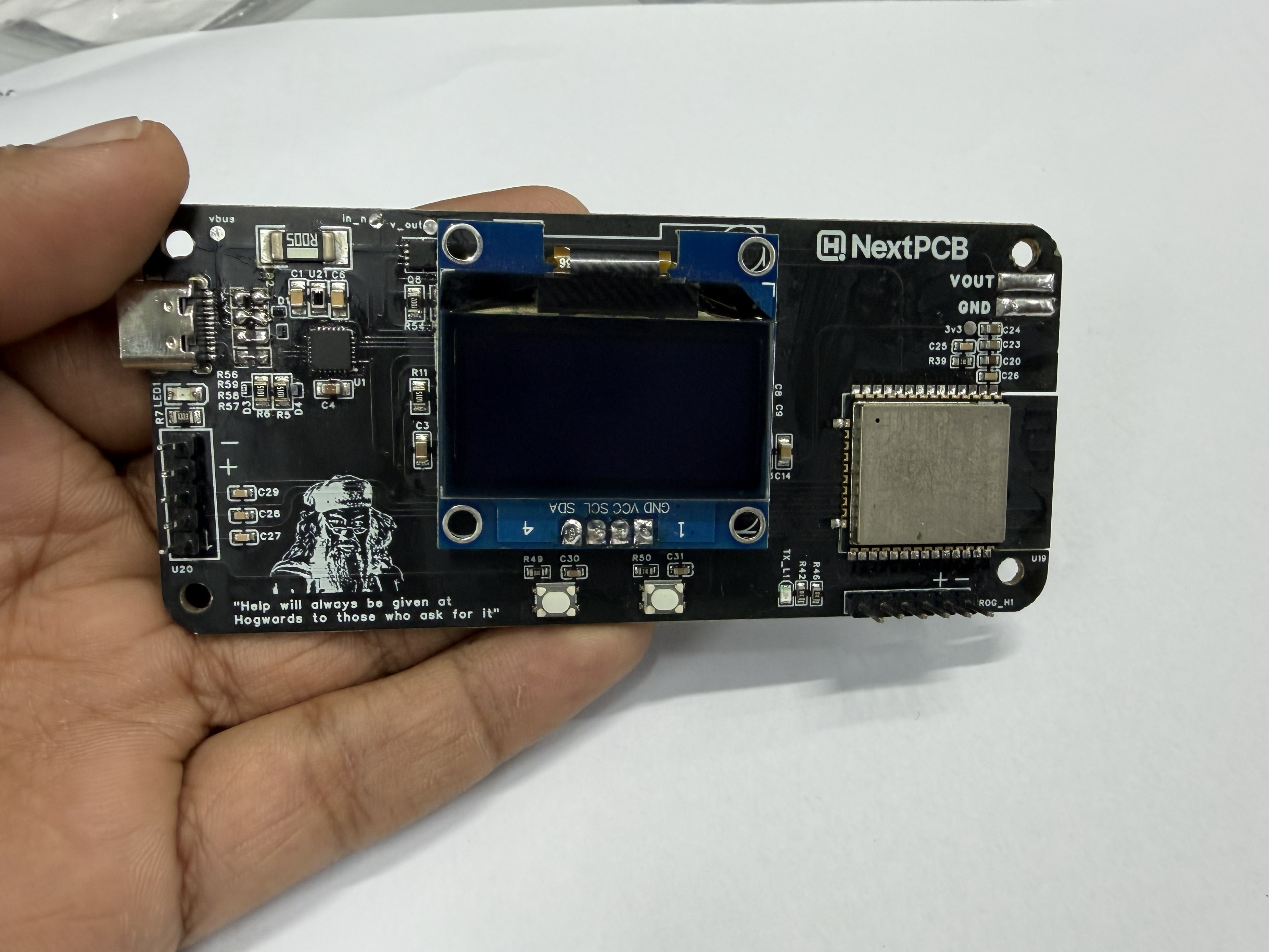
For fabrication and assembly, I used NextPCB.
After generating the Gerber files, BOM, and pick-and-place data, the files were uploaded for assembly. Before shipping, assembly photos were provided so the component placement could be verified.
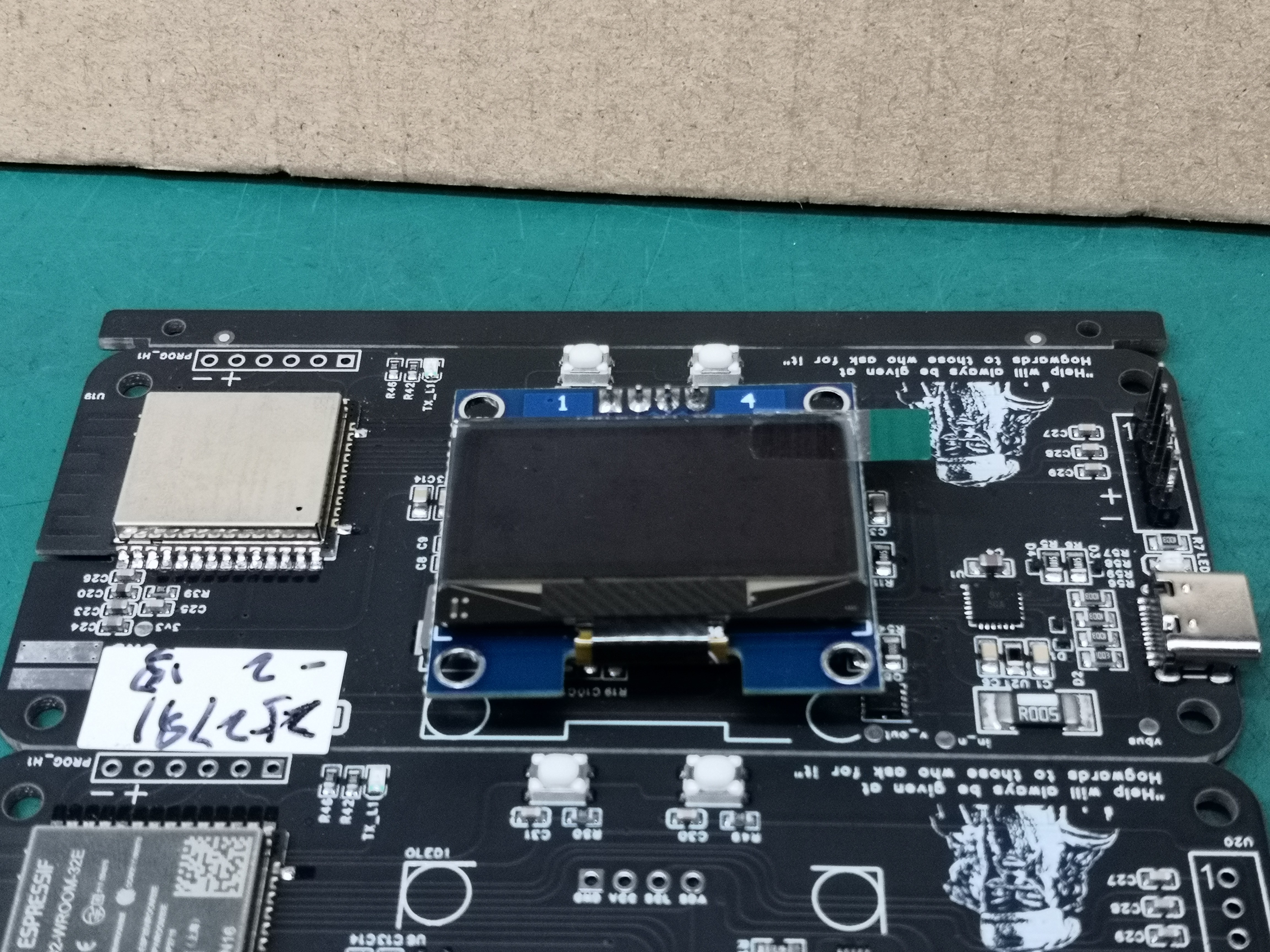
Sponsored by NextPCB
This project was successfully completed with the support of NextPCB, a reliable multilayer PCB manufacturer. With over 15 years of experience in PCB fabrication and assembly, NextPCB offers high-quality and dependable PCB solutions for makers and professionals worldwide.
You can order high-quality PCBs starting at $1.9, and multilayer PCBs starting at $6.9:
https://www.nextpcb.com/pcb-quote
Get free PCB assembly for up to 5 boards:
https://www.nextpcb.com/pcb-assembly-quote
With comprehensive Design for Manufacture (DFM) analysis features, HQDFM is a free, sophisticated online PCB Gerber file viewer.
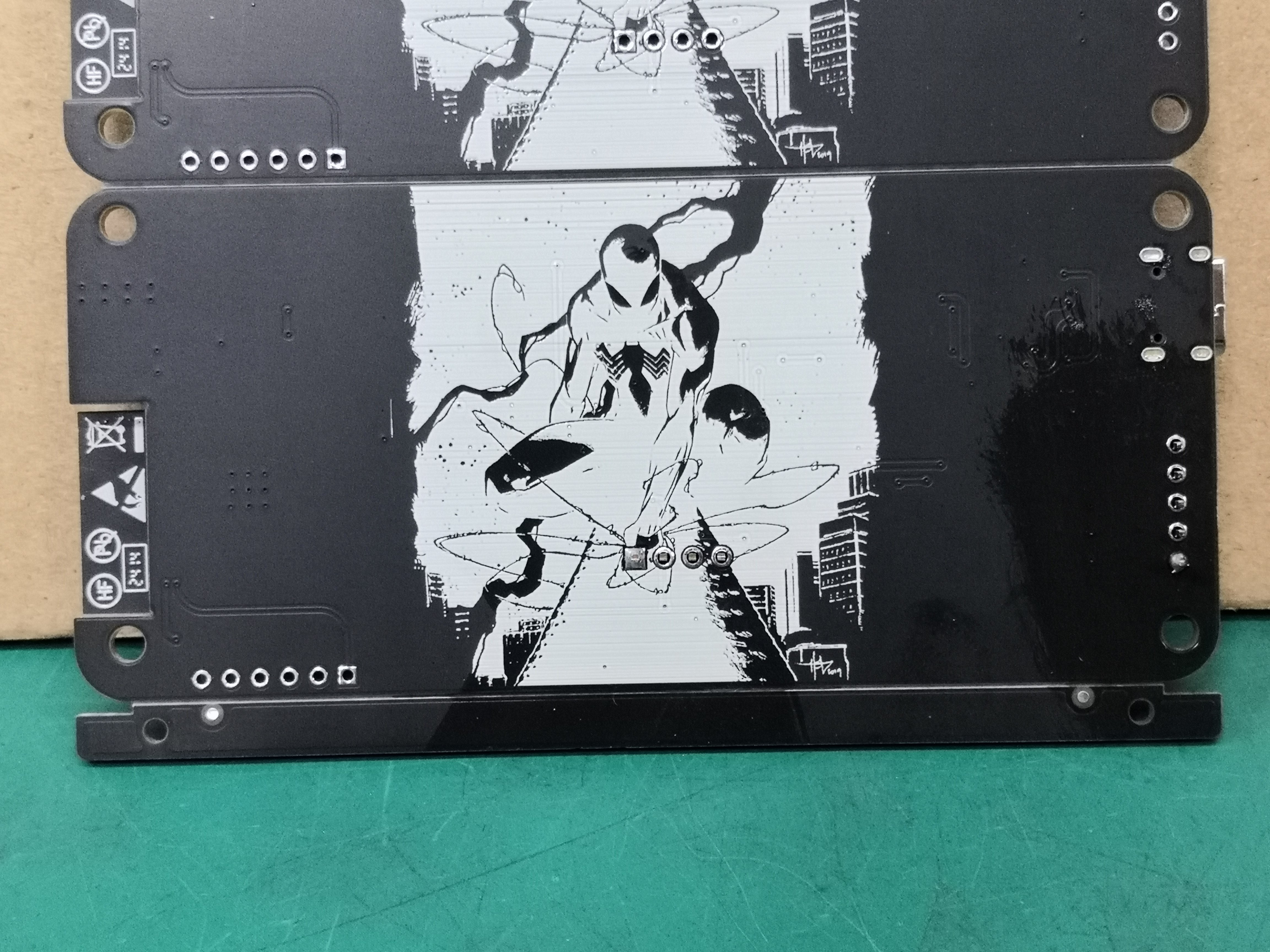
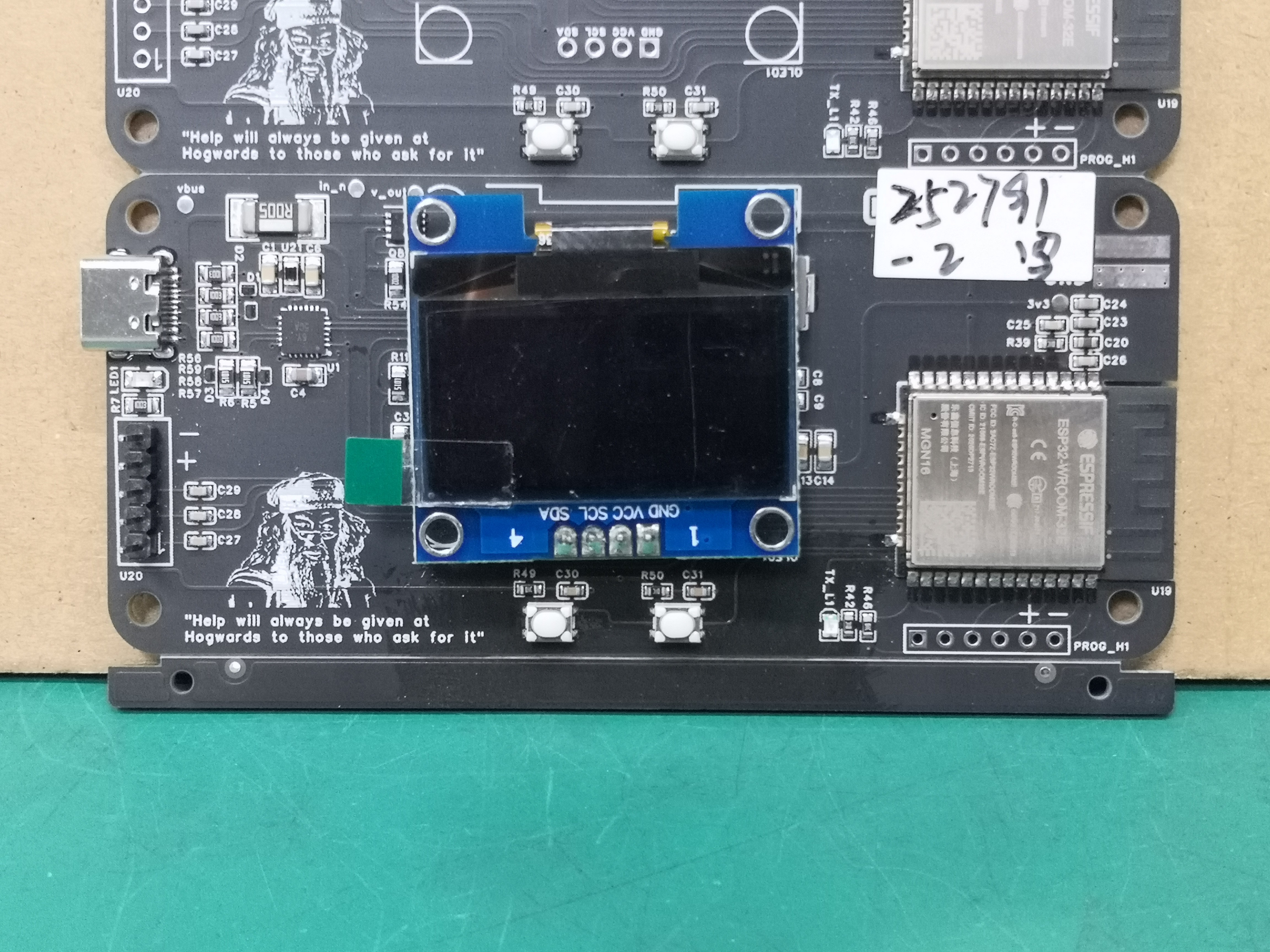
Once the boards arrived, the only remaining step was flashing the firmware and beginning hardware testing.
FIRMWARE
The firmware was developed using the Arduino framework.
A custom AP33772S library was written specifically for this project to simplify USB-C PD and PPS communication.
The firmware handles:
- PD/PPS voltage negotiation
- INA226 measurement
- OLED display
- Rotary encoder
- Output switching
- Adafruit IO communication
- System monitoring
On startup, the ESP32 reads the available PD profiles from the connected charger and presents them through the user interface.
If you'd like to build your own PowerPD, I've included the Gerber files, BOM, and schematic in the GitHub repository.
ENCLOSURE
The enclosure was designed in Autodesk Fusion 360 and consists of three main parts:
- Front panel
- Main housing
- Rotary encoder knob

The design was kept compact while still providing access to the OLED display, USB-C connector, output terminals, and controls.

All enclosure parts can be printed using standard PLA on a desktop 3D printer.
TESTING
Testing was performed using several USB-C PD chargers supporting different power profiles.
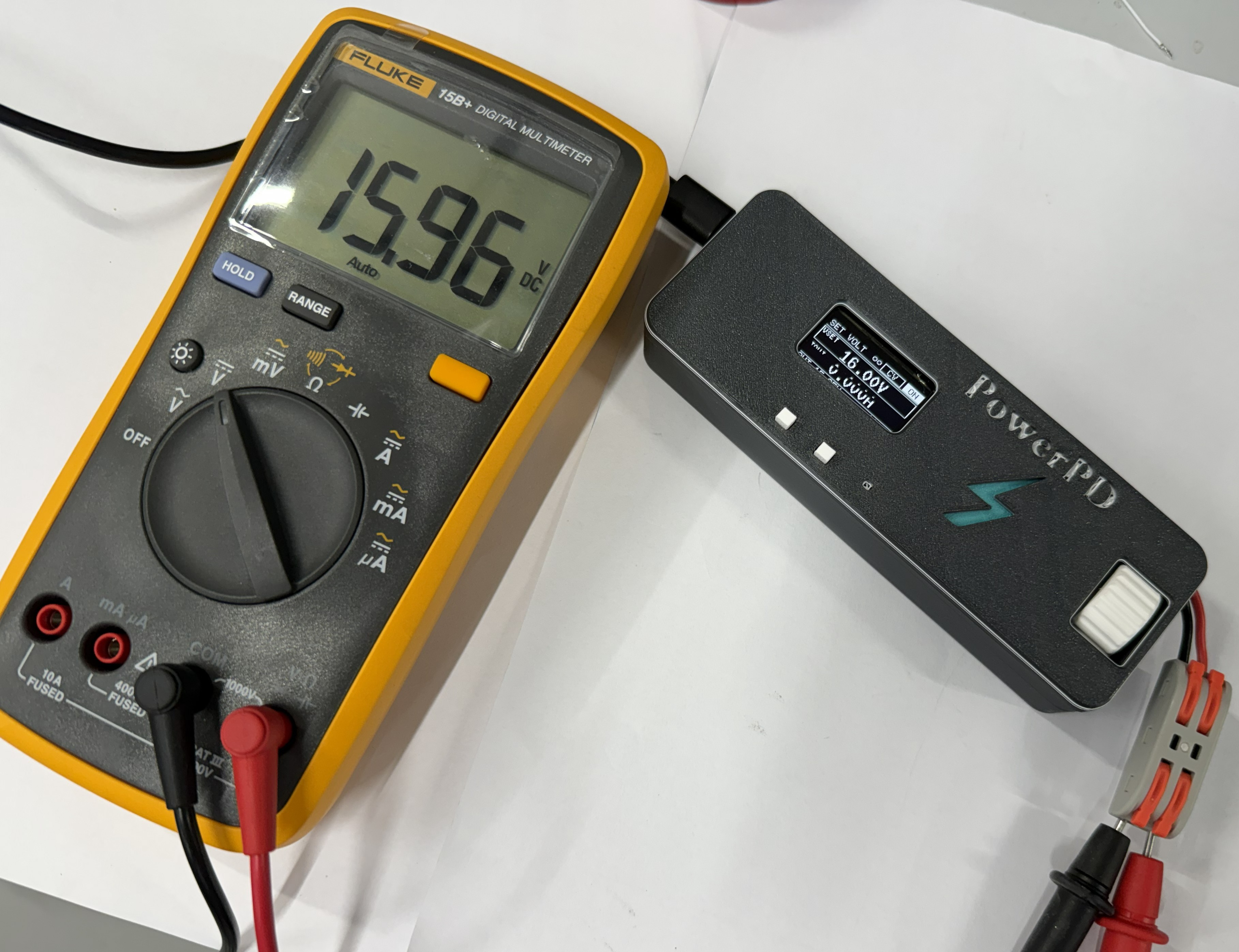
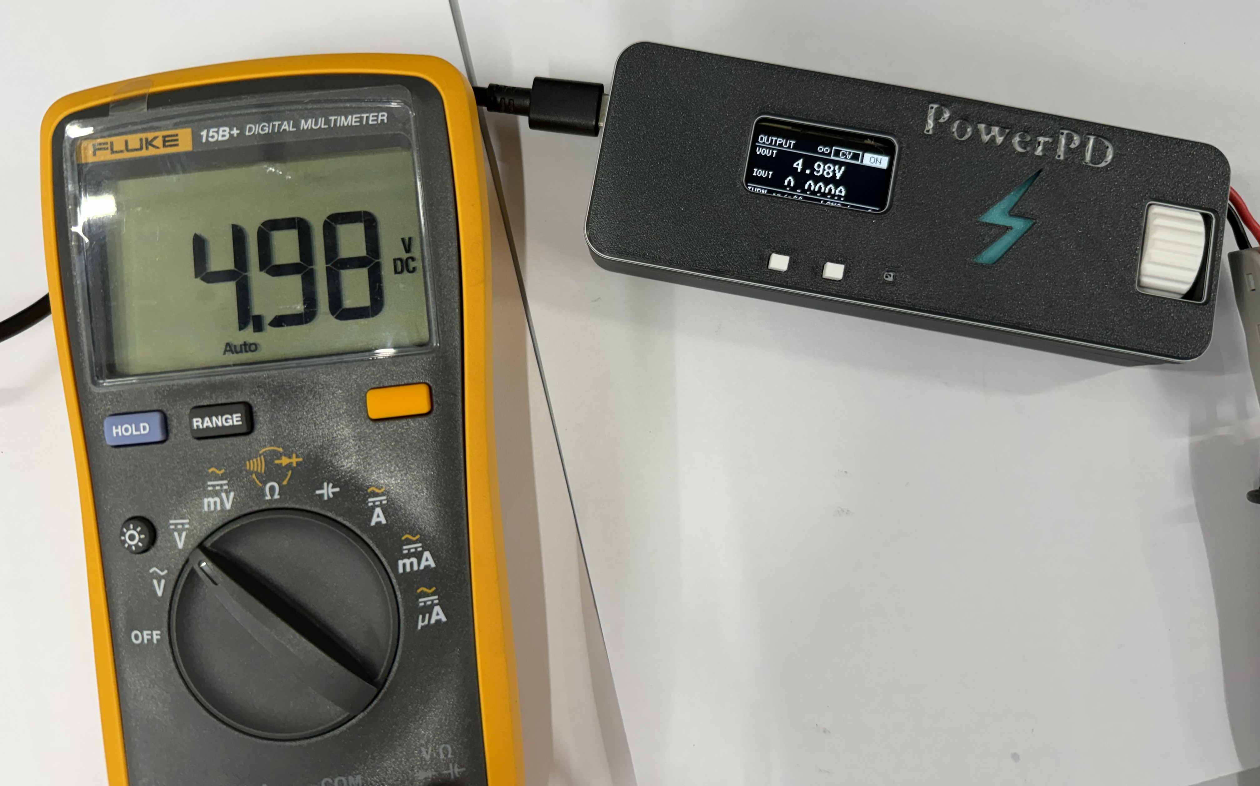
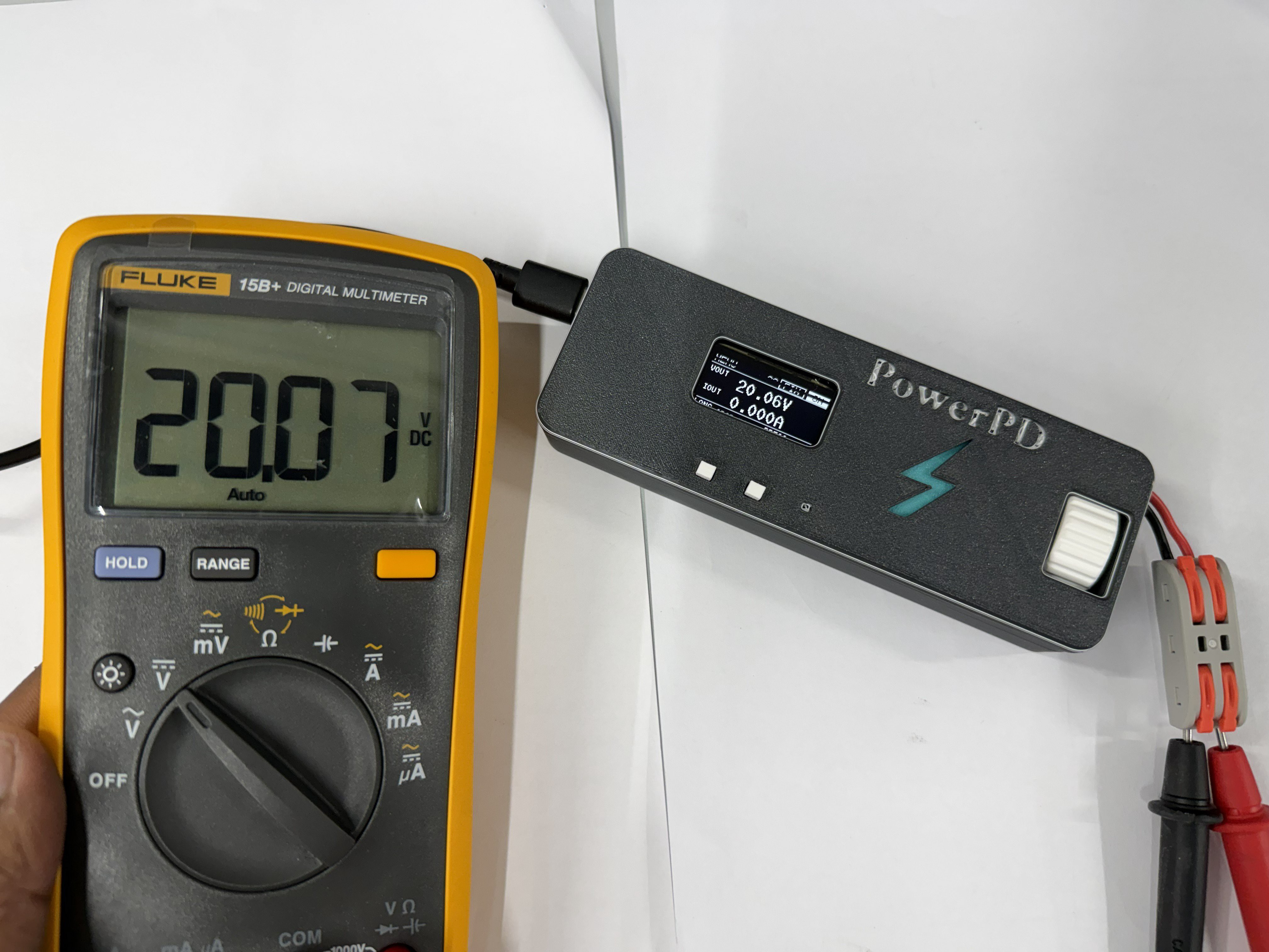
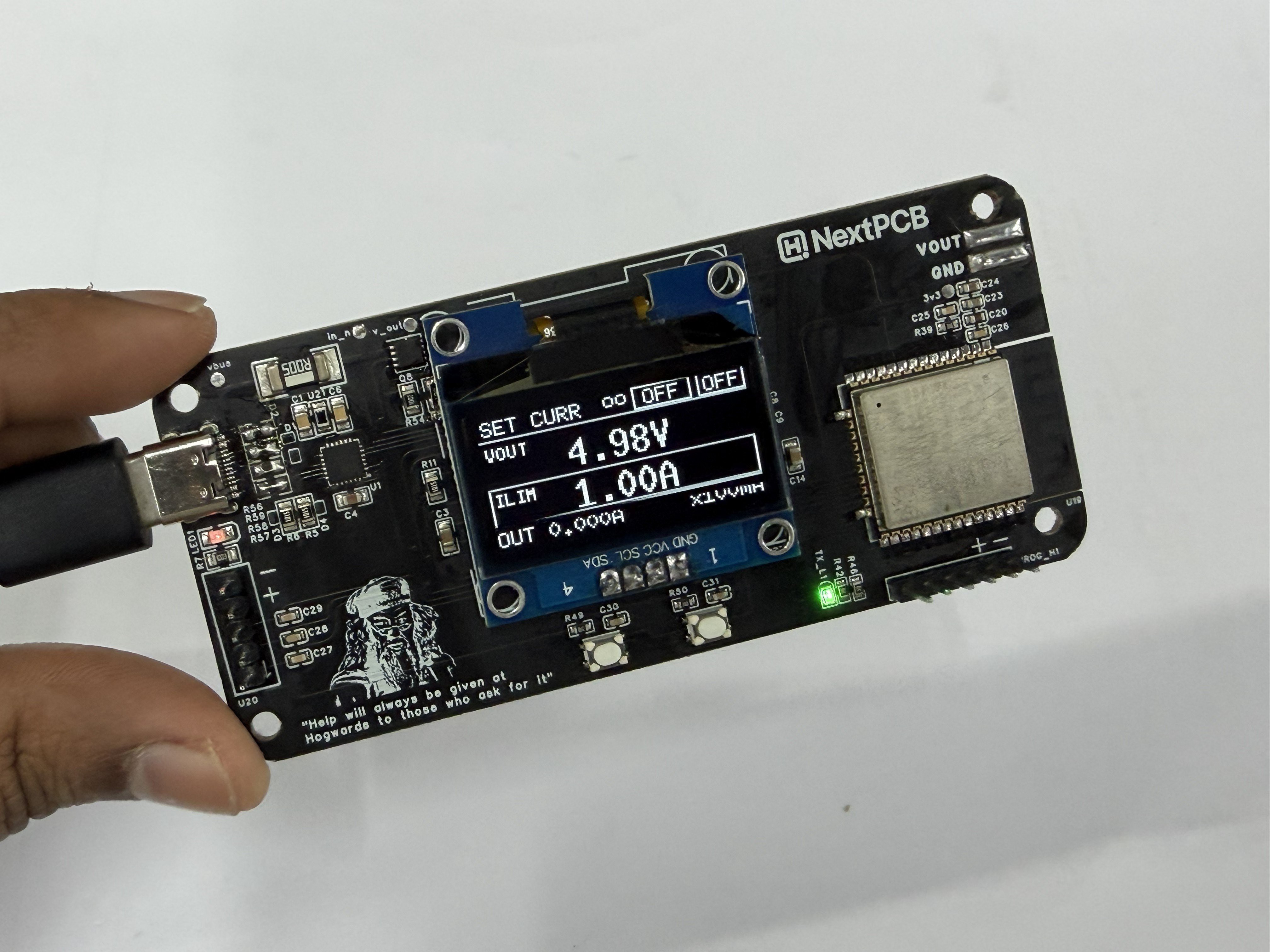
After powering the board, I verified the negotiated output voltages using a multimeter. The measured values closely matched the values reported by the INA226 and displayed on the OLED.
I also tested PPS operation by selecting intermediate voltages through the rotary encoder and confirming the resulting output voltage....
Read more »





 Daniel Knezevic
 Sagar 001
 Ludwin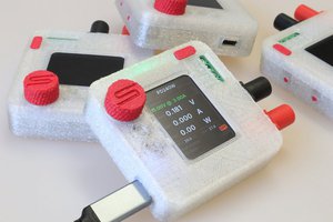
 Theo Heng
This looks SO cool. If the project works well it would be nice to swap out the MP1584 Buck Converter for one that can do 48V to 60V to support PoE devices. PoE++ require 52.0–57.0V at the PSE and >2A out.