 Daniel Knezevic
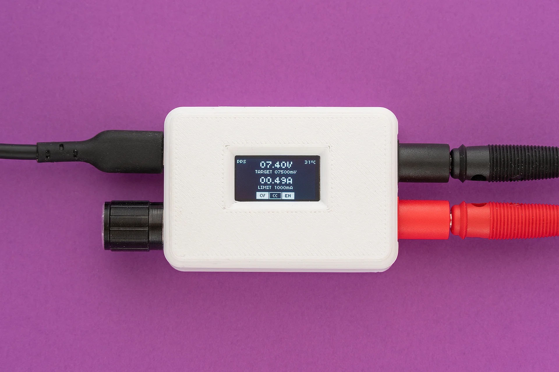
TinyPPS is a pocket-sized programmable power supply built on the USB Power Delivery (PD) standard and the USB Programmable Power Supply (PPS) feature. It transforms a standard USB-C PD charger into a flexible bench-style power source by negotiating selectable output voltages and current limits directly with the charger.
Key features
TinyPPS takes advantage of pin-compatible USB PD sink ICs (AP33772 and AP33772S), providing two feature sets within a single firmware, depending on the selected IC:
| Feature | With AP33772s | With AP33772 |
|---|---|---|
| Supported PDO profiles | fixed PDO, PPS | fixed PDO, PPS |
| Output voltage range | 3.3 - 21V | 3.3 - 21V |
| Max output current* | 5A | 5A |
| PPS voltage step size | 100mV/Step | 20mV/Step |
| Programmable current limit | 250mA/Step | 50mA/Step |
| User-switchable output | ✅ | ✅ |
| Over Voltage Protection (OVP) | ✅ → Hard Reset and Auto Restart | ✅ → Auto Restart |
| Over Current Protection (OCP) | ✅ → Output Disable | ✅ → Auto Restart |
| Under Voltage Protection (UVP) | ✅ → Output Disable | ❌ |
| Over temperature protection (OTP)** | ✅ → Output Disable | ✅ → Output Disable |
| Short-Circuit Protection (SCP) | ✅ → Output Disable | ✅ → Output Disable |
*charger and cable dependent
**OTP is set to 85°C
The idea
Everything started with buying a 15$ USB powered mini SMD hot plate that required a supply with the following capabilities: PD65W 20V 3.25A. By acquiring a 100W power supply I have found out something called PPS, beside regular voltage/current values, on the label.
PPS 3.3V-21.0V - 5.0A 100W max - tickled my brain. What is PPS? It turned out it is a neat USB-C feature. To be more precise, it is an advanced feature of the USB Power Delivery (USB PD) 3.0 standard that allows chargers to dynamically adjust voltage and current in real time. Unlike standard PD, which uses fixed voltage “steps” (e.g., 5V, 9V, 15V, 20V), PPS allows for fine-grained adjustments - typically in 20mV voltage increments and 50mA current steps.
Knowing this, I came up with the idea of using USB PPS to build a small “lab” power supply as a proof of concept. Before jumping in to realisation, I explored existing solutions and stumbled upon PocketPD by Centylab. Inspired by this great project, I came up with an idea to create my own solution and use this opportunity to learn new skills.
Sponsor time
Huge thank you to PCBWay for providing me PCBs and SMD stencil for free.
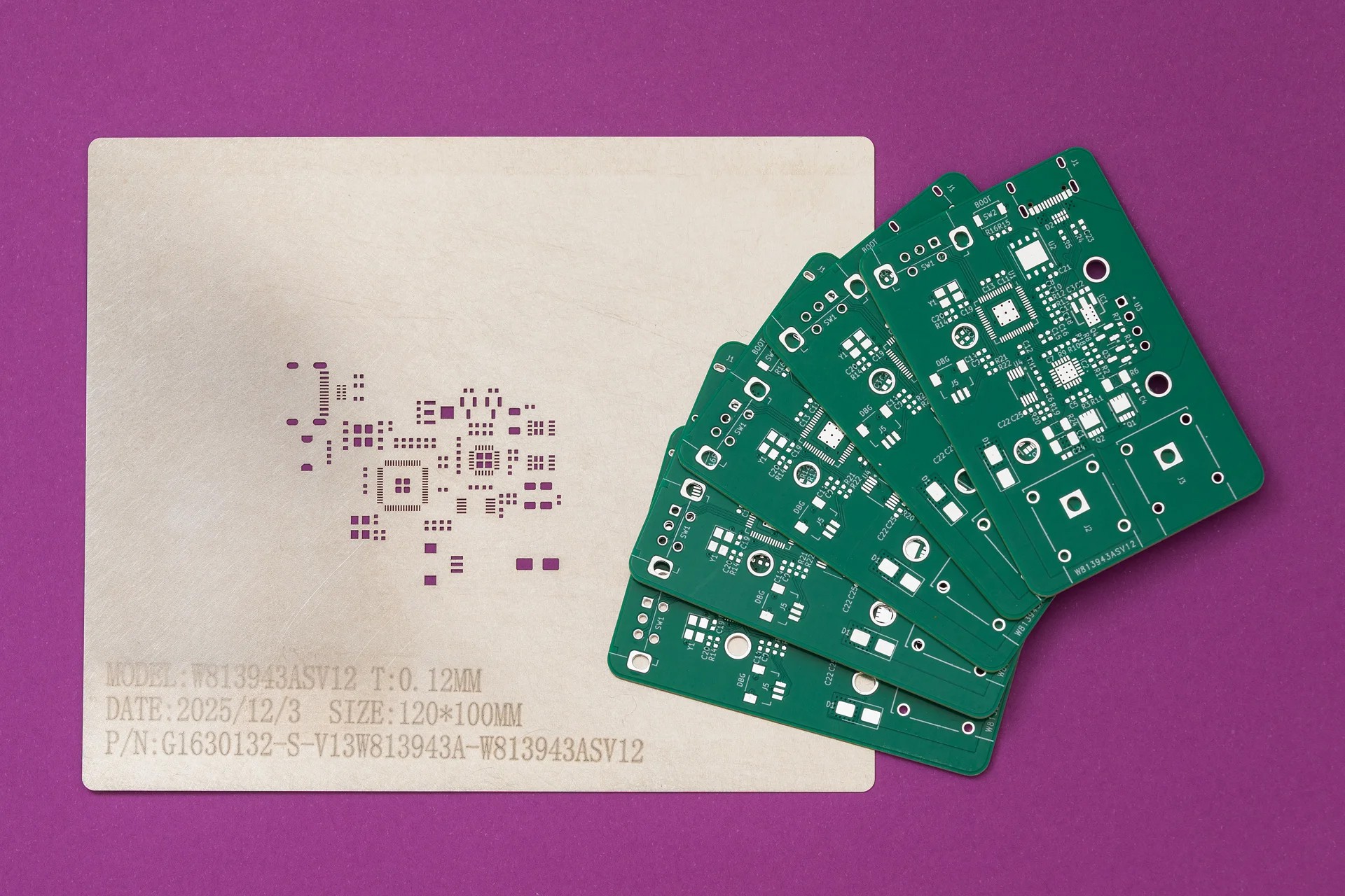
PCBWay offers high-quality PCBs at affordable prices. The boards are ready to solder straight out of the box, with no leftover tabs that need to be sanded down. Ordering is super easy: just upload the Gerber files and select the desired parameters.
What I like most is their customer support. They are quick to review orders and don’t just point out issues - they provide detailed explanations on how to address them. Whether it is about a missing Gerber file or out of capabilies issue. At the end, the outcome is always positive.
Hardware
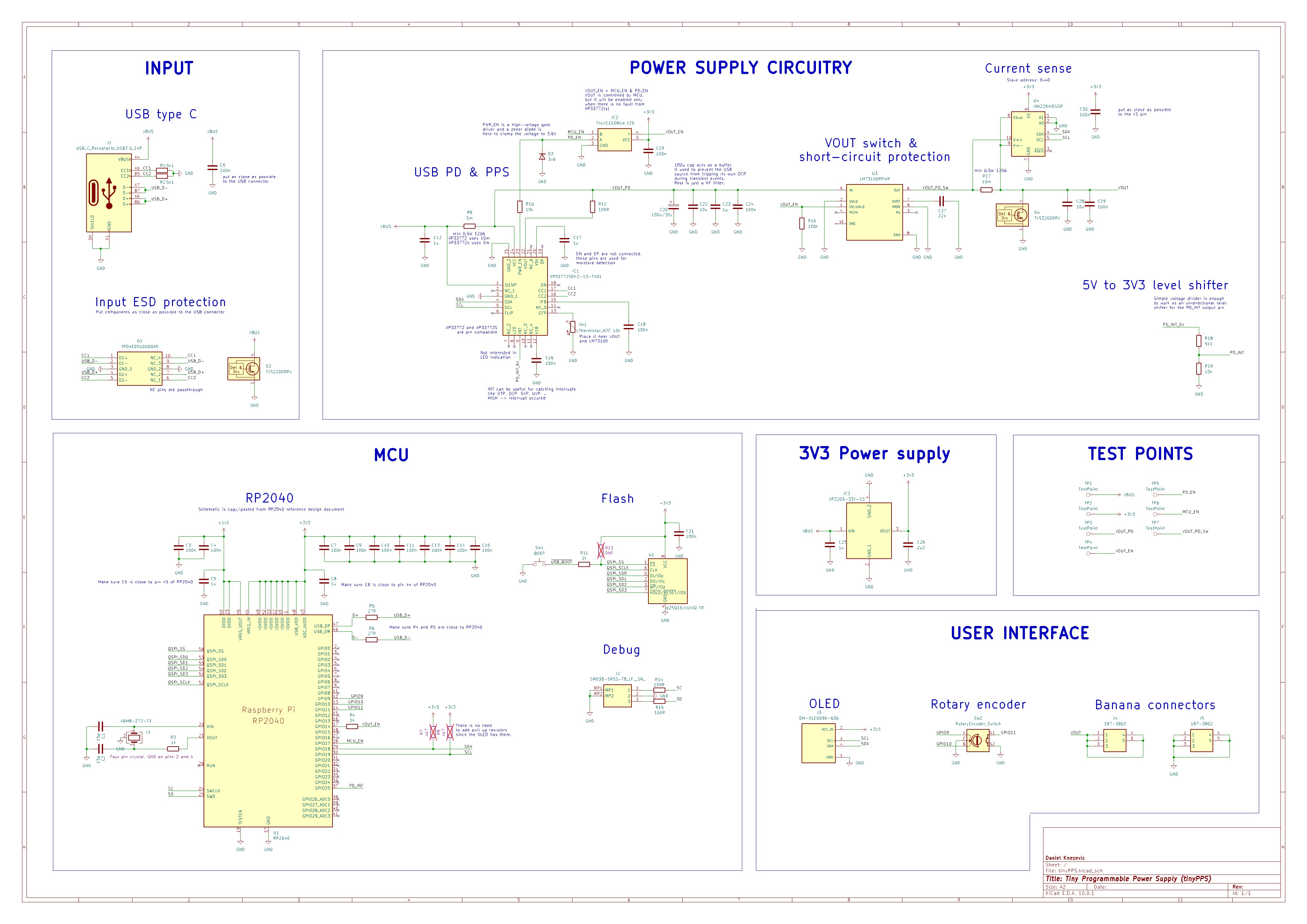
For this project I wanted to use a microcontroller family other than ESP32. Options were Raspberry Pico-series or STM32. Due to ease of use (mostly flashing) I have chosen the Pico - RP2040.
The schematic started as an amalgamation of a few reference designs - mostly RP2040, AP33772S and INA226, with an OLED, rotary encoder and some extra connectors added on top.
When I realised the older AP33772 variant provides smaller voltage and current steps for PPS compared to AP33772S I tweaked the schematic to handle both USB PD sink controllers. The good thing is that these two ICs are pin compatible.
Schematic and PCB are designed in KiCAD 10:
Difference between AP33772 and AP33772S
Shunt resistor: AP33772 requires a 10 mΩ shunt resistor while AP33772S requires 5 mΩ.
VOUT control: While AP33772S has an option to manually enable/disable the output via the VOUTCTL bit in the SYSTEM register, the AP33772 enables the output automatically upon successful PD negotiation. To support both ICs and have the same...
Read more »