shlonkin
-
log 4: challenges and lessons
10/14/2017 at 13:22 • 0 commentsWay back I mentioned making this thing speak gcode, which would greatly improve its usefulness for the masses. I tried to do it. I got stuck learning about gcode and trying to figure out the best way to make it happen. Sadly I've had to accept the fact that I just don't have time for that right now. So for now it will just speak my own custom language for transmitting instructions to the plotter. That's not such a bad thing. It has worked fine for me so far.
Another thing I've had to accept is the limitations of this technique. I learned this lesson with my "Automate the art" project as well. The image is just not going to look as good as I want it too. With lots of tuning and way too much time spent I might end up with something OK, but then I have to ask myself "Was it worth it?" In some cases, yes. But usually not.
I want to include something positive in this log too. I learned many things and increased my proficiency with coding and machine making. I produced a nice little plotter that works very well and can now draw crosshatched pictures that look pretty good. I also built an egg-bot type machine for drawing on balls that can make use of the same code.
I hope that someone else is finding this project useful or educational. If so, then at least I can say it has accomplished the goal of the hackaday prize: making something that matters.
Oh, I almost forgot. Here's the arduino code that I promised before. (See the files for this project.)
-
log 3: progress update and video
09/27/2017 at 12:23 • 0 commentsIt's been a while since my last update. I've been... busy. I made a video of the little plotter drawing some pictures with a very rough description of what's going on. Here it is.
So, about that busyness. I finally got a 3D printer and I've been producing lots of toys for the kid, robots for me, and parts for projects. I also drew up and printed a thing like an egg-bot to draw on ping pong balls. I tried this crosshatching code with it and it worked, but the thickness of the marker combined with the tiny canvas just makes it too messy. Oh well, it was just for fun.
As for code updates, I fixed a couple simple bugs and cleaned a bit, but it is functionally the same. I wanted to make a gcode version, but found my gcode skills are lacking, so it still makes use of the clumsy protocol for talking to an Arduino. It works fine, but is worthless unless I upload the Arduino side of the code. I'll get that up this week.
-
log2: Hardware - test plotter built
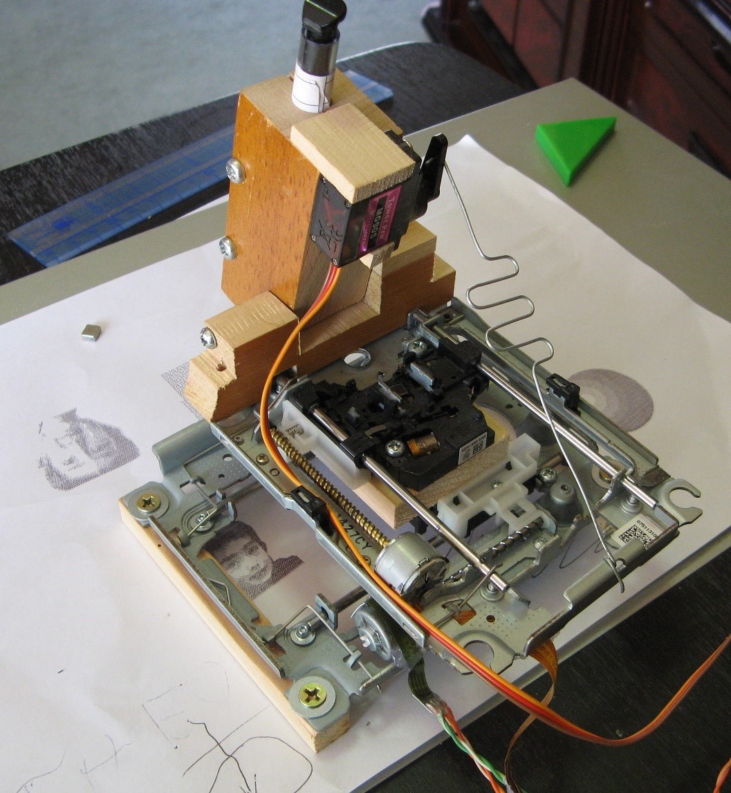
04/27/2017 at 14:15 • 0 commentsHardware - Keep in mind that this is not the main part of the project. It is simply an easy to make testing device for the software. Everyone and their cousin has built a little plotter out of optical drive mechanisms, so it's nothing too exciting. On the other hand, it might inspire other beginner tinkerers to make something fun using parts from their junk pile.
Sorry, I didn't take many progress pictures, but it is pretty easy to figure out just by looking at it.
![]()
Here's a brief overview.
- The two metal mechanisms were taken from junk DVD drives. Don't bother with CD drives as they just have geared DC motors rather than steppers.
- A chunk of wood was screwed to the plastic optics carriage on on drive. The second was placed perpendicular to the first and its carriage was then screwed to the wood as well. It should be as precisely perpendicular as possible.
- Some scrap wood was cut into a hinge shape and attached to the upper drive. A pen is inserted through a hole in the moving piece of wood.
- A servo is attached to the wood and a piece of steel wire runs from the actuating arm to the upper drive's frame.
- The wire is bent into a simple spring to keep a light pressure between pen and paper.
- To keep it securely in place, strong magnets are attached to the base and it sits on a steel surface. This holds the paper and the machine securely, but can simply be lifted up to move the paper.
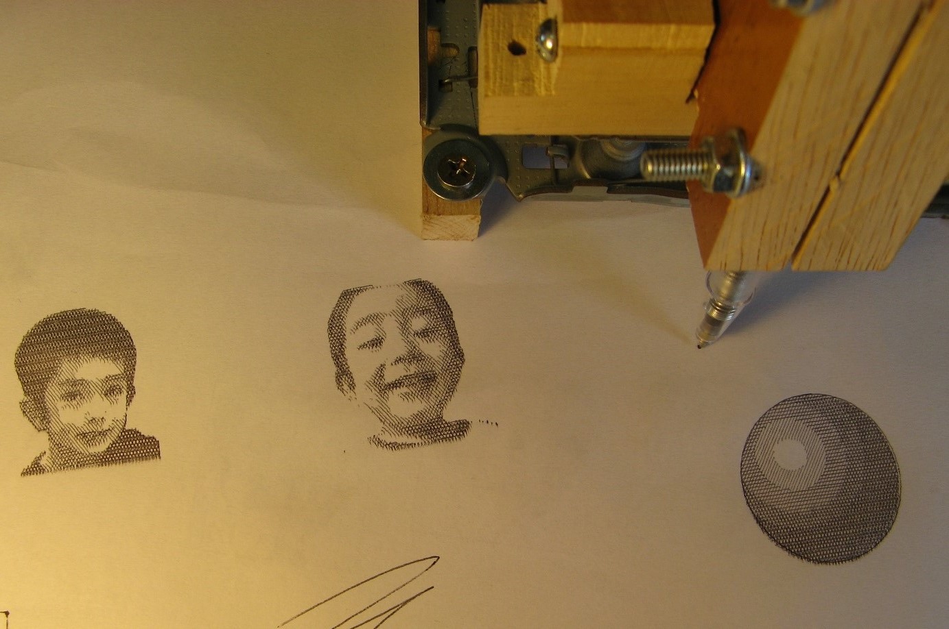
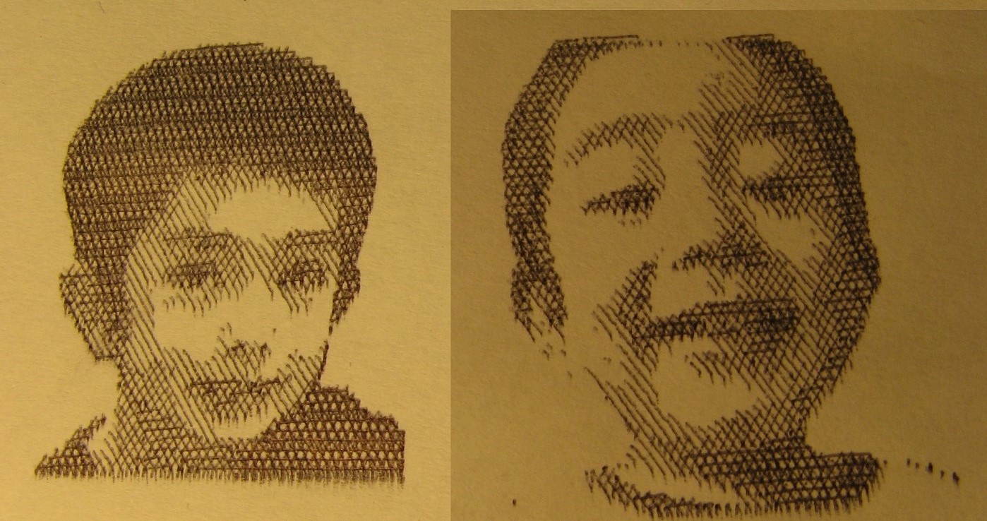
Tests - As you can see above, I have drawn several pictures using the crosshatching software, which by the way is the main portion of this whole project and is still in early development.
Anyway, these pictures are all about 3x3cm which is really very small. Despite the tiny size in relation to the pen stroke resolution, I was able to get some really clear images with fine detail. I am happy. Oh, and these were made using four hatch levels/angles.
![]()
![]()
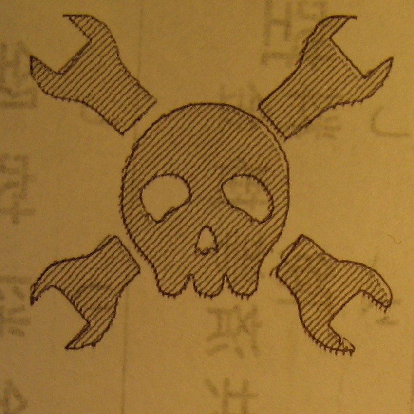
And to show the ability to draw both vector paths(from SVG files) as well as shading, here is your favorite logo. By the way, that writing you see was just something printed on the other side of the paper.
![]()
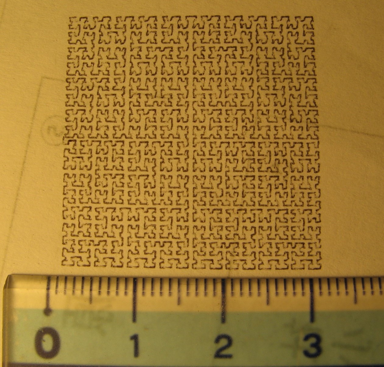
And while I'm at it, I like to explore the resolution and reliability of the plotter by drawing a tiny Hilbert curve.
![]()
What's next? In the next log I should be giving you the arduino portion of the code used in the plotter as well as a schematic. Stay tuned.
-
log 1: Initial code offering and outline
04/10/2017 at 12:59 • 0 commentsSoftware: As you can gather from the pictures, the basic algorithm has been implemented and it works well. But it is far from complete. Here I'll describe what I have so far and present the (probably buggy)code to you.
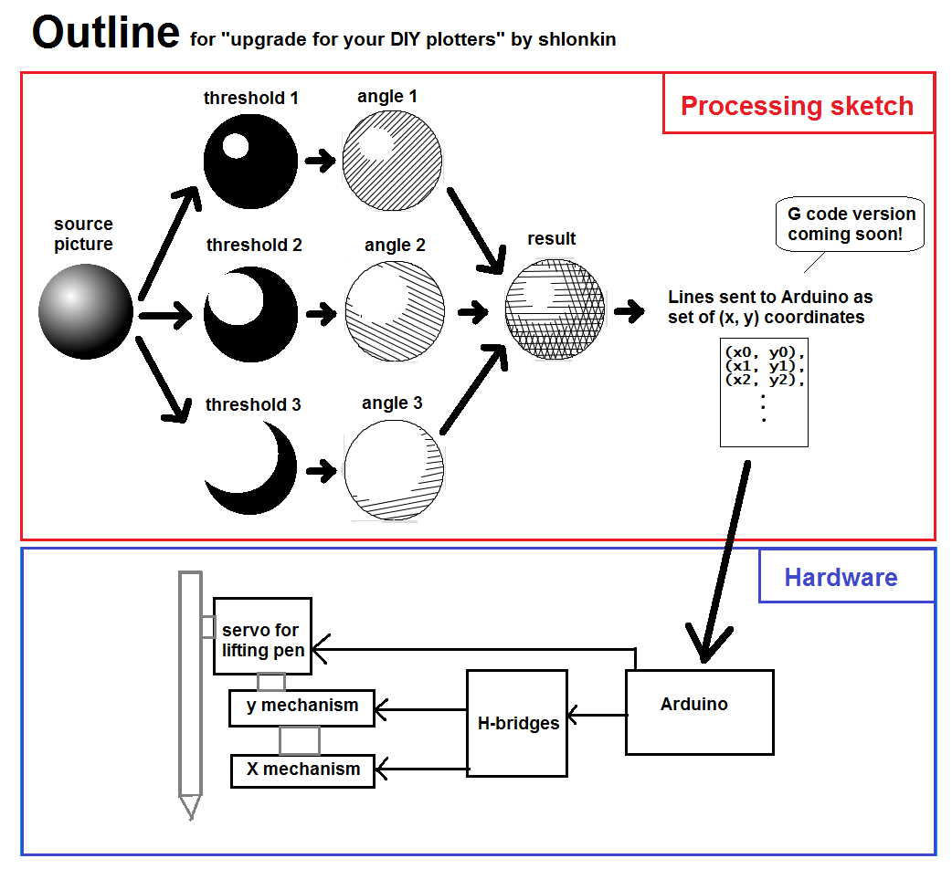
An outline, in graphical format to reduce wordage.
![]()
I hope that makes sense. If not, ask questions.
For now the coordinates are sent to the Arduino using a protocol I made up long ago for another plotter. It is simple and works well enough, but I know that's not what you want, so I plan to make a G-code/Grbl type version to make it more useful for you. Just wait a while.
Here's the package: HatchPlotter.zip (also found in the files section)
It contains the Processing sketch in its current form as well as two example picture files. Just extract the HatchPlotter folder into your Processing sketch folder and run it. It should draw the example picture.
Hardware: Those X and Y mechanisms are DVD drive assemblies. They contain small stepper motors which move the laser carriage in the usual way. The carriages, the chunks that hold the laser and optics, are attached firmly to each other so that their motion is perpendicular. One outer frame is stationary and the other is free to move in the horizontal plane. The moving one carries the pen and servo parts.
I'm sorry for this vague text description. It will be clear once I get things put together and take pictures.
Upgrade for your DIY plotters
Make better use of all your CNC plotter projects with cross hatching