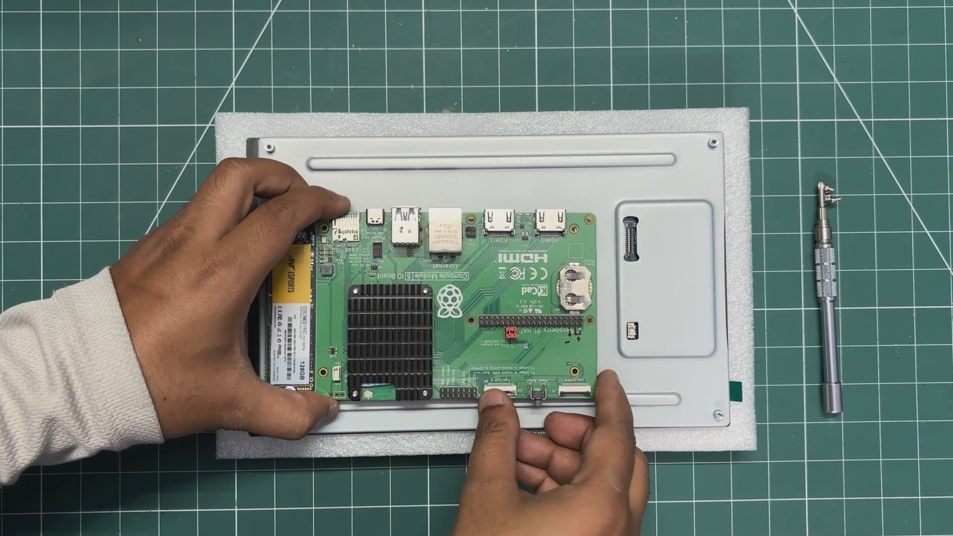
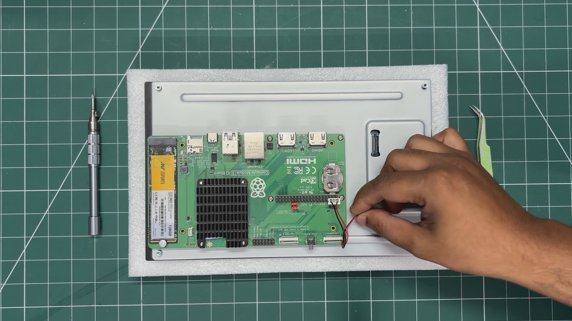
We begin the display and CM5 assembly process by positioning the expansion board over the back of the display.
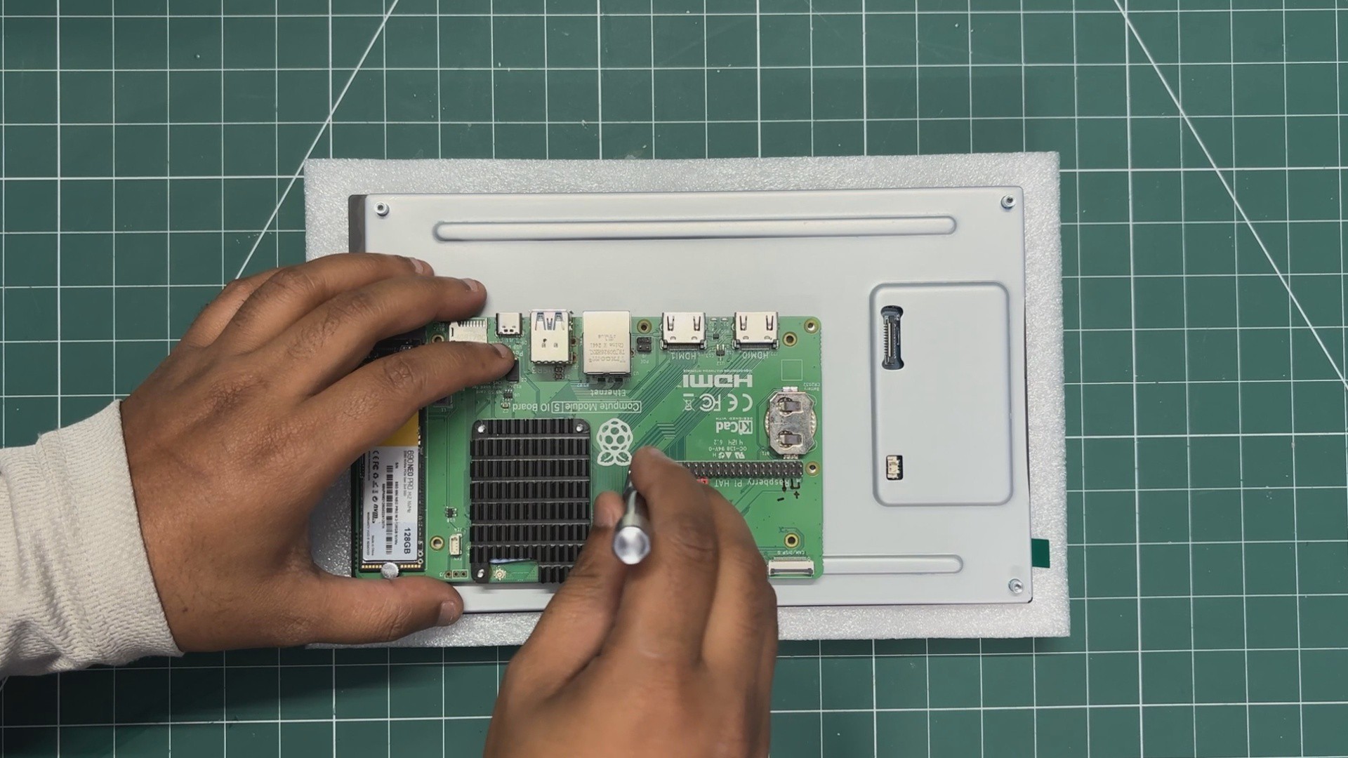
We align the mounting holes of the display with the Raspberry Pi board and then use the provided four M2.5 bolts to secure both of them together.
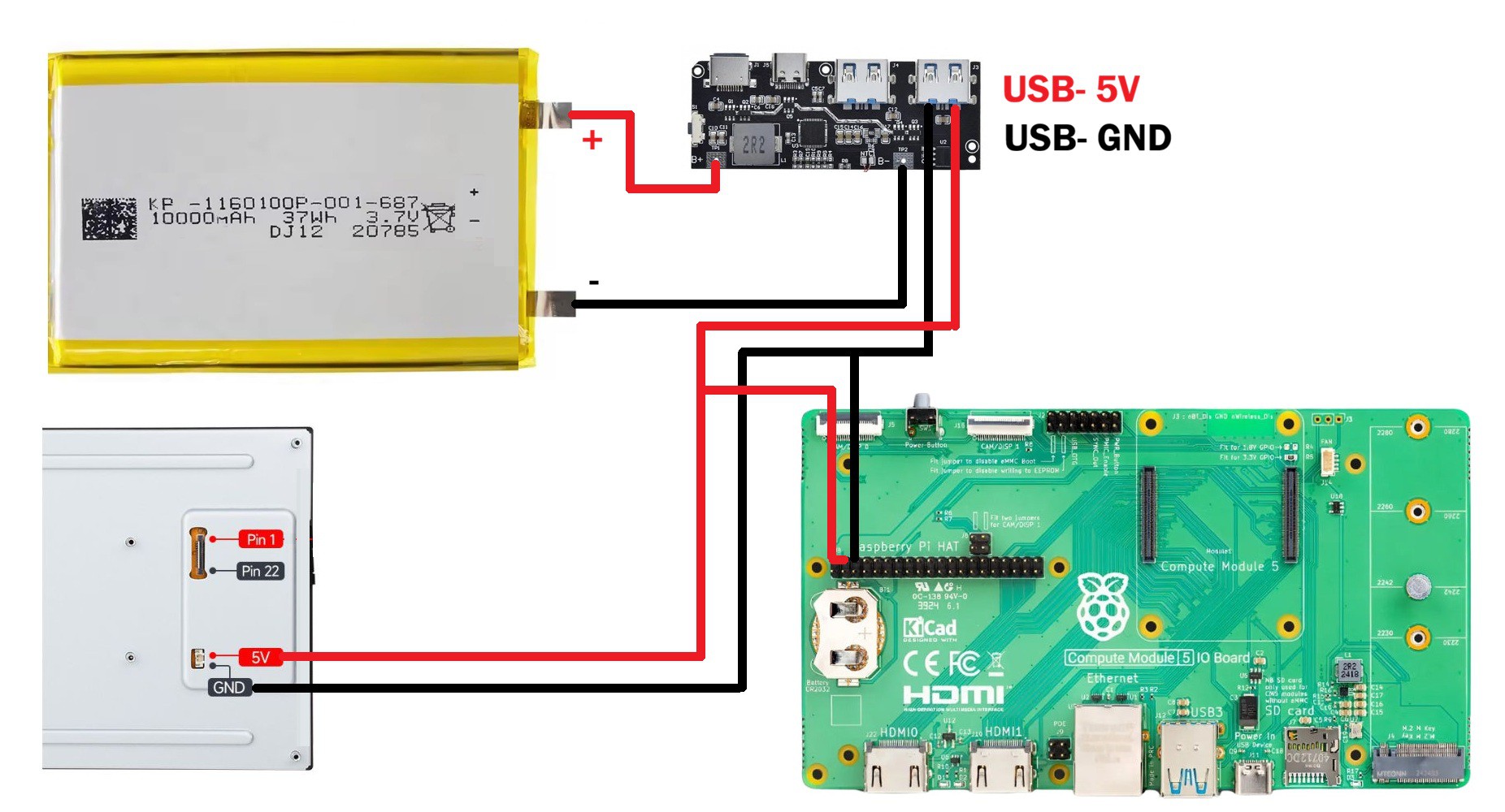
Next, we connect the power wire harness. One side is connected to the JST connector on the display, while the other end goes to the Raspberry Pi's GPIO header. We connected 5V to 5V and GND to GND. Basically, the display will be powered directly from the GPIO header of the Raspberry Pi.
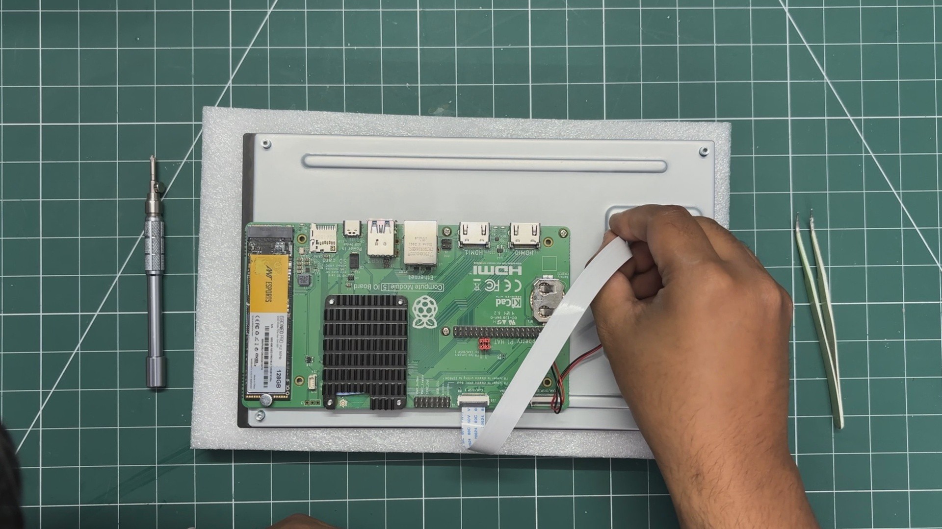
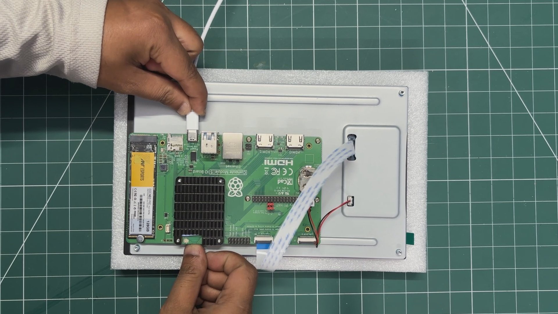
Next, the FPC cable is added. We first connect it to Port 1 on the Raspberry Pi expansion board and then connect the second end to the display's FPC connector.
2
CONFIG FILE EDIT
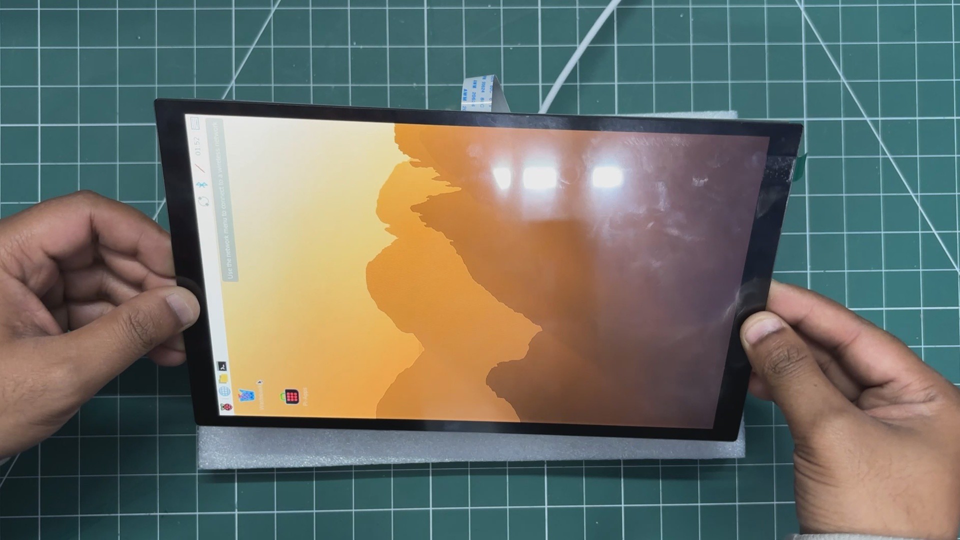
We plugged in the power and were hoping this would be a plug-and-play job, but things are never that simple, and the display didn't work straight away.
We needed to connect an external monitor to our CM5, open a terminal, and then edit the config.txt file.
We added the following line at the bottom of the file.
On the wiki page for this display, to Waveshare's credit, they did include a custom pre-flashed Raspberry Pi OS Trixie image. If we use that image and flash our Raspberry Pi with it, the display boots up without requiring any manual edits to the configuration files.
3
FRAME ASSEMBLY
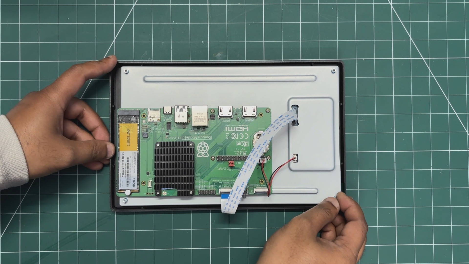
Frame assembly begins with the placement of the display and Raspberry Pi assembly into their designated position.
Here, we didn't need to use any adhesive, as the display will be locked in place once the back part is added.
4
POWER SOURCE- SMARTPHONE PD CHARGER
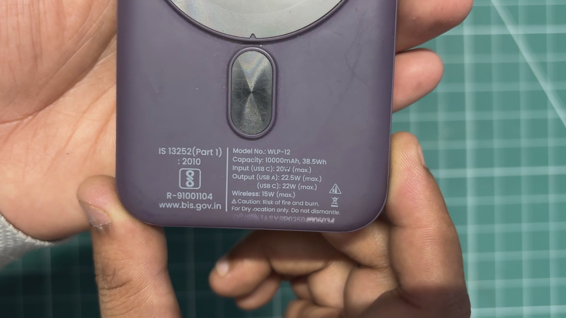
For the power source of the tablet, one of the best options is to harvest the power circuit and lithium cell from a power bank. Here, I used a PD power bank that I normally use for charging my iPhone and other devices. It can provide both power input and power output through its USB Type-C port, along with a stable 5V 3A output from its USB port.
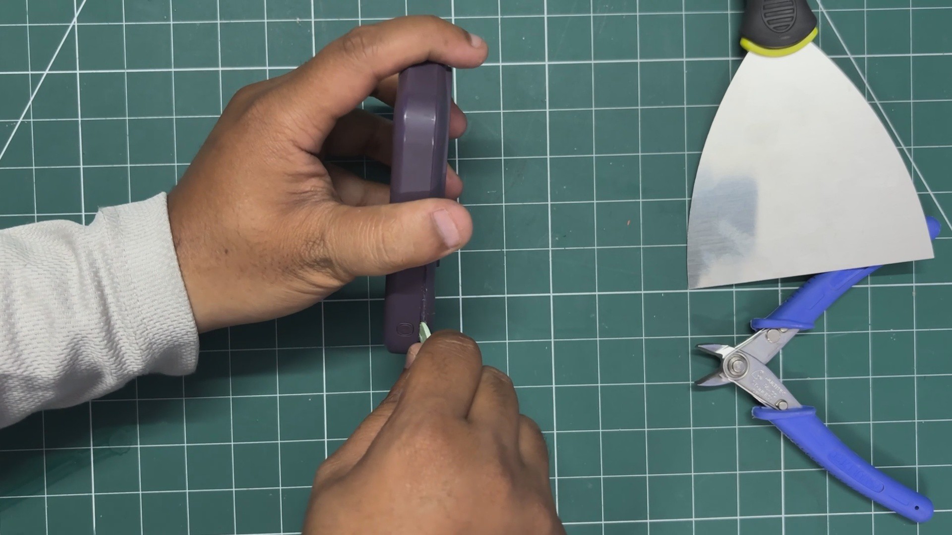
Using a prying tool, we started opening the power bank. I didn't have a proper pry tool available, so I used the back side of a pair of tweezers.
By inserting it along the seam of the enclosure and applying a bit of pressure, the two halves of the body started separating.
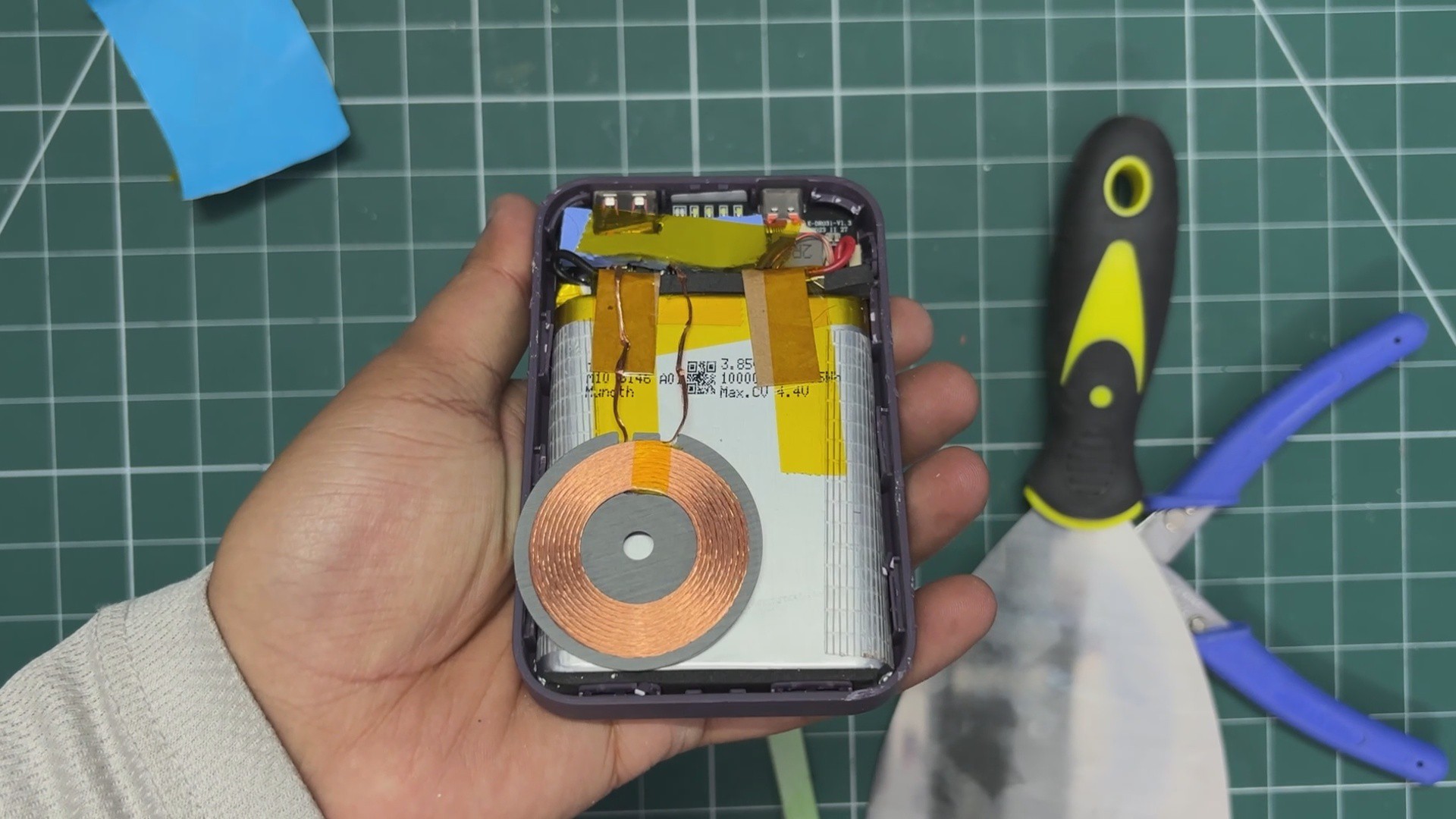
The enclosure was held together using snap locks, so once we created an opening on one side, we inserted our pry tool into the gap and moved it along the edge to completely remove the lid.
Doing that completely separated both parts. The circuit was secured in place with M1.8 screws, which we removed.
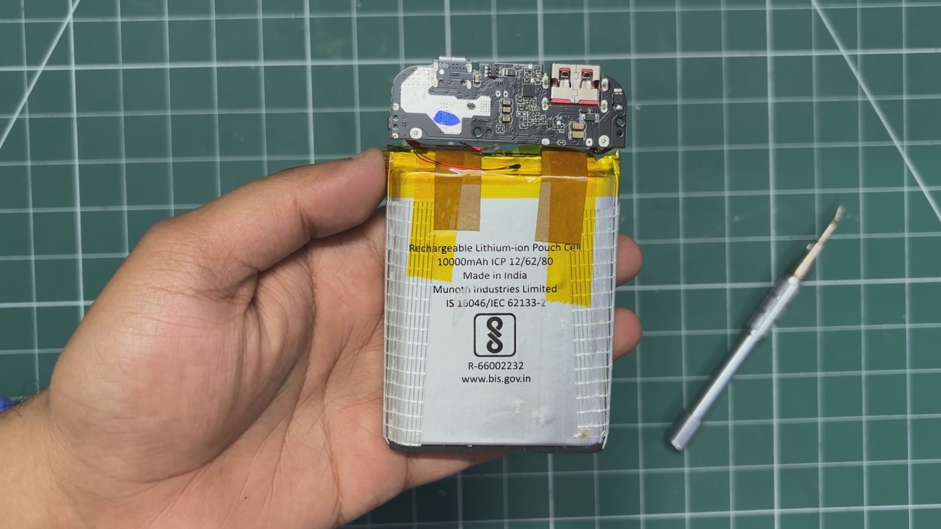
The battery was also secured with adhesive tape, so by applying a little pressure, it came off as well.
This was a MagSafe charger, so it also included a charging coil, which we removed from the circuit.
As a result of this harvesting process, we ended up with a 10,000mAh battery and a power circuit capable of powering our display and Raspberry Pi setup.
5
POWER SOURCE ASSEMBLY
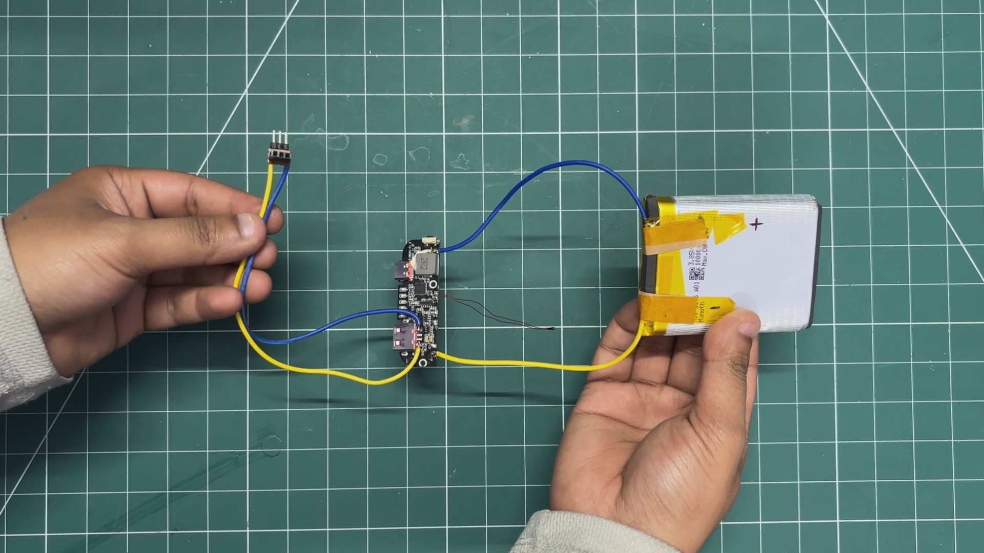
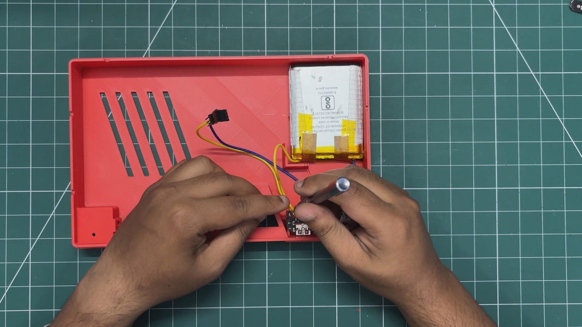
After harvesting the lithium-polymer cell and charger circuit from the power bank, we extended the battery wires by desoldering the original wires and replacing them with longer ones.
We connected the battery positive terminal to the B+ pad on the circuit and the battery negative terminal to the B- pad.
Next, we soldered two output wires to the USB port's 5V and GND terminals. For connecting these output wires to the Raspberry Pi header pins, we added a CON3 female header connector to the 5V and GND wires.
With this header connector, we can simply plug it onto the Raspberry Pi's GPIO header 5V and GND pins, which power the entire setup.
6
POWER SOURCE TEST
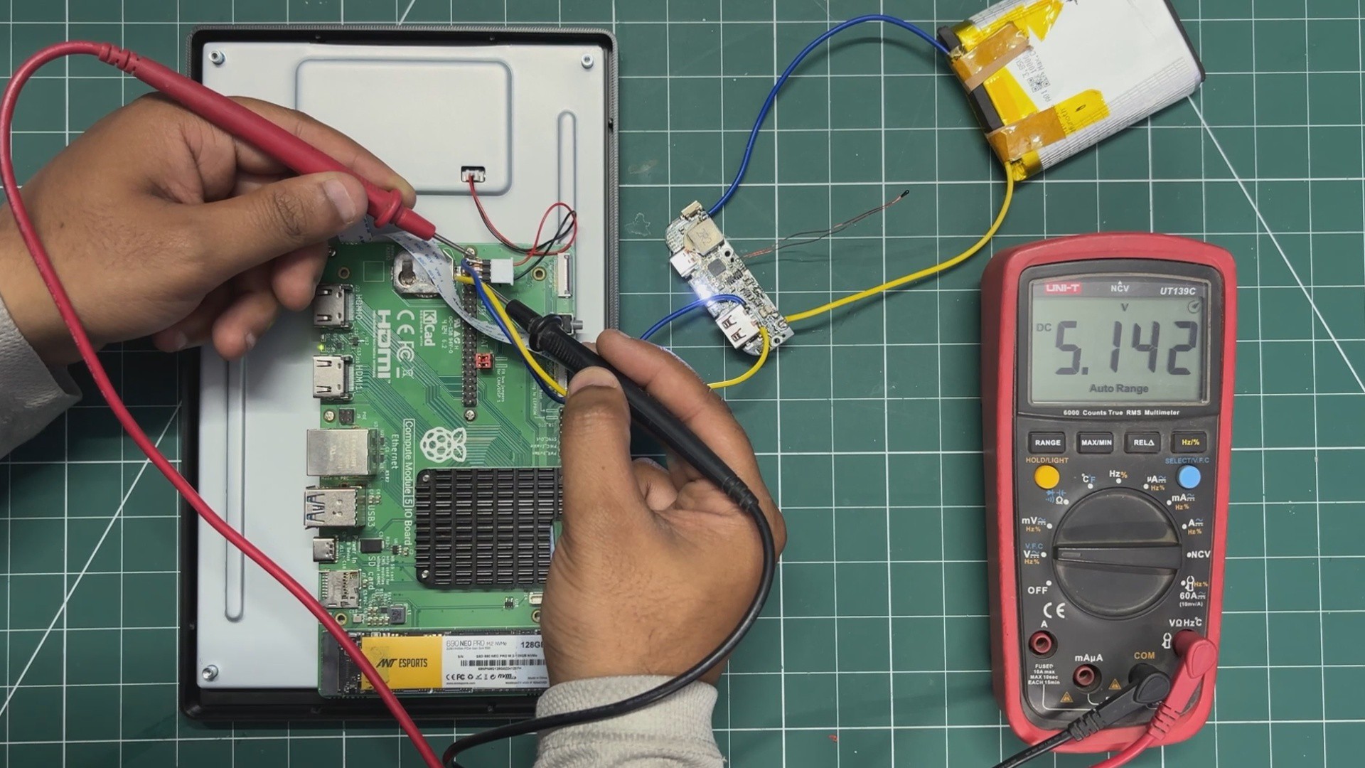
Before putting things together, we checked the output voltage using a multimeter. We measured 5V, which confirmed that the setup was working correctly.
Within 5 seconds of turning on the power circuit, the Raspberry Pi booted into the desktop environment, showing that the setup was functioning properly.
Long-pressing the power button on the power circuit for three seconds turns the device off.
7
POWER SOURCE - BASE ASSEMBLY
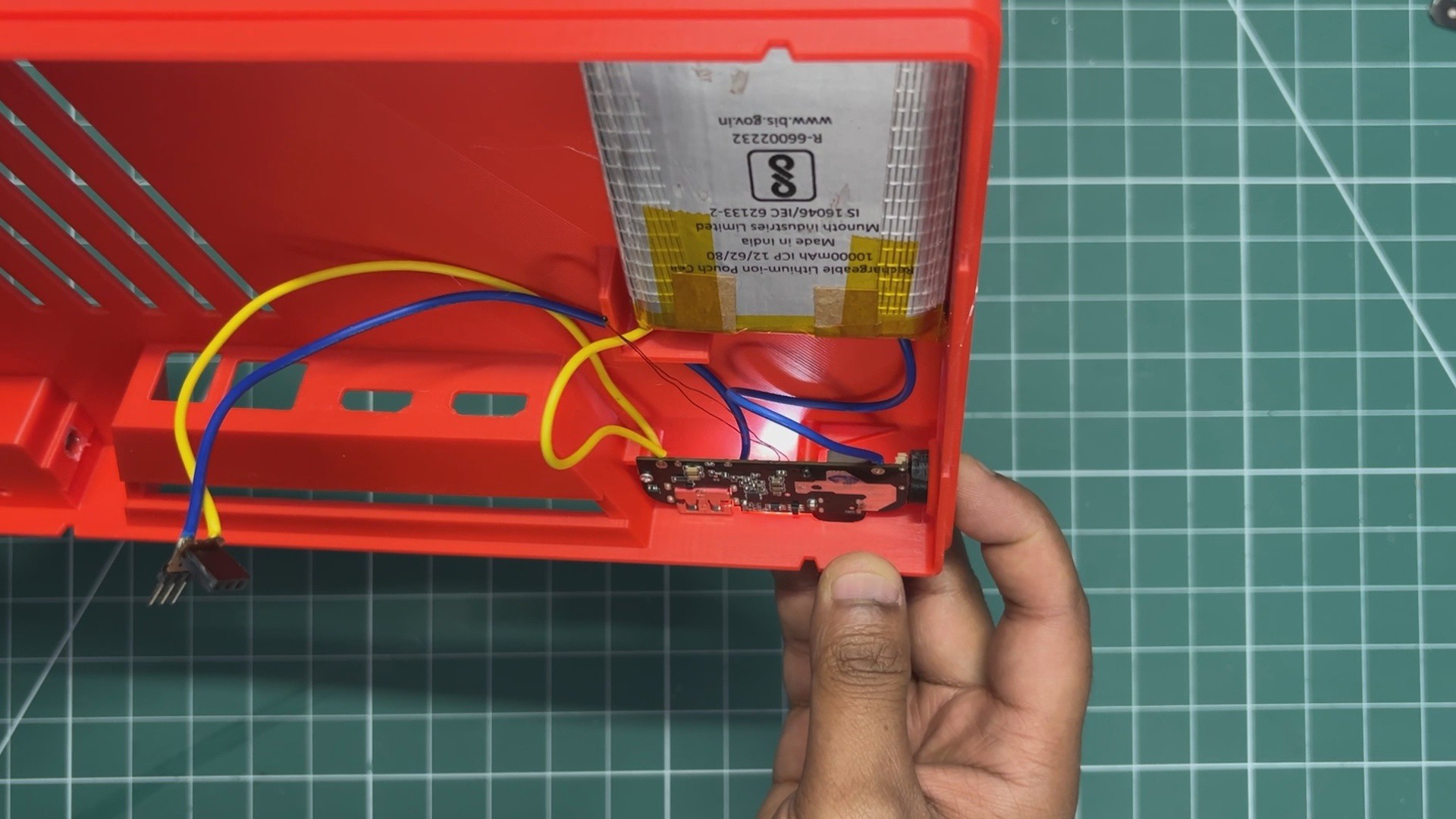
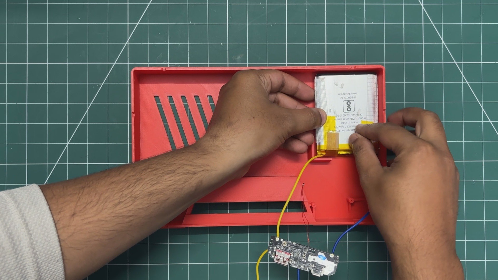
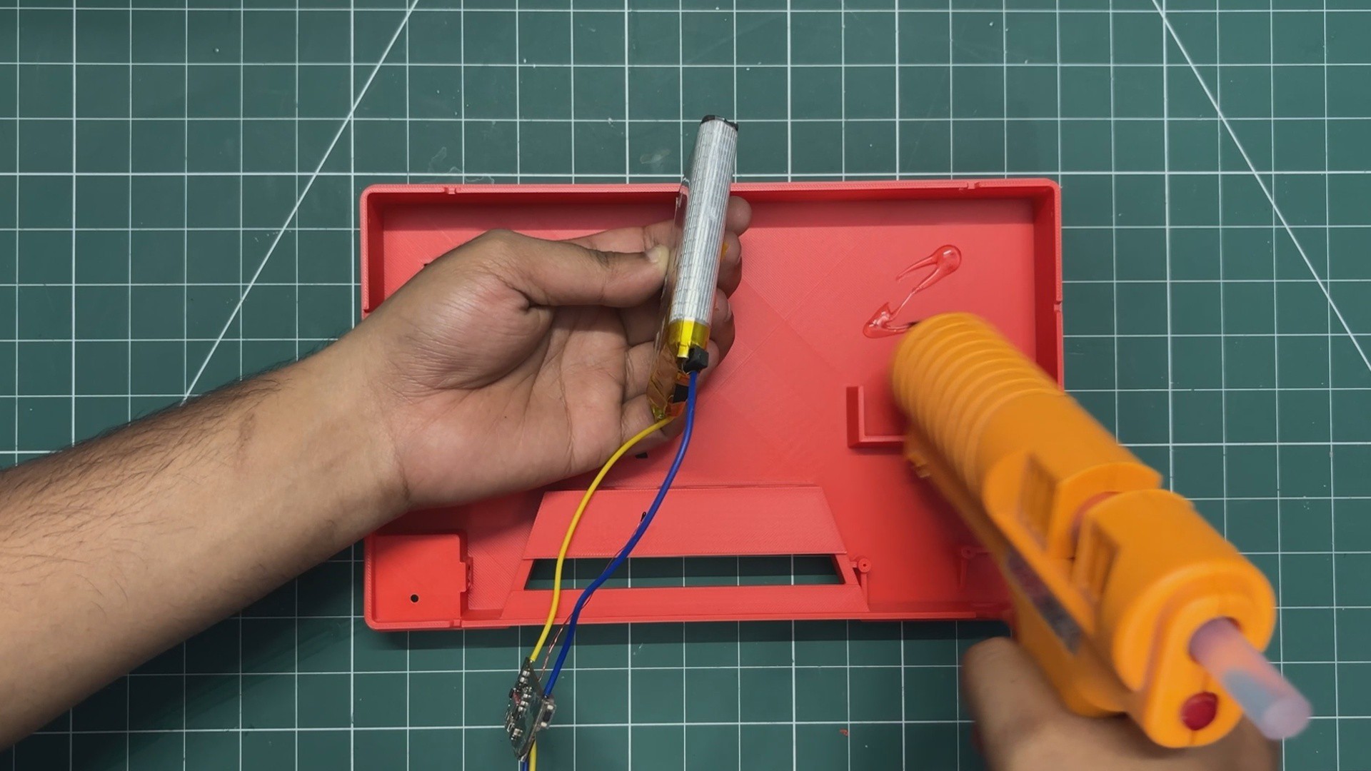
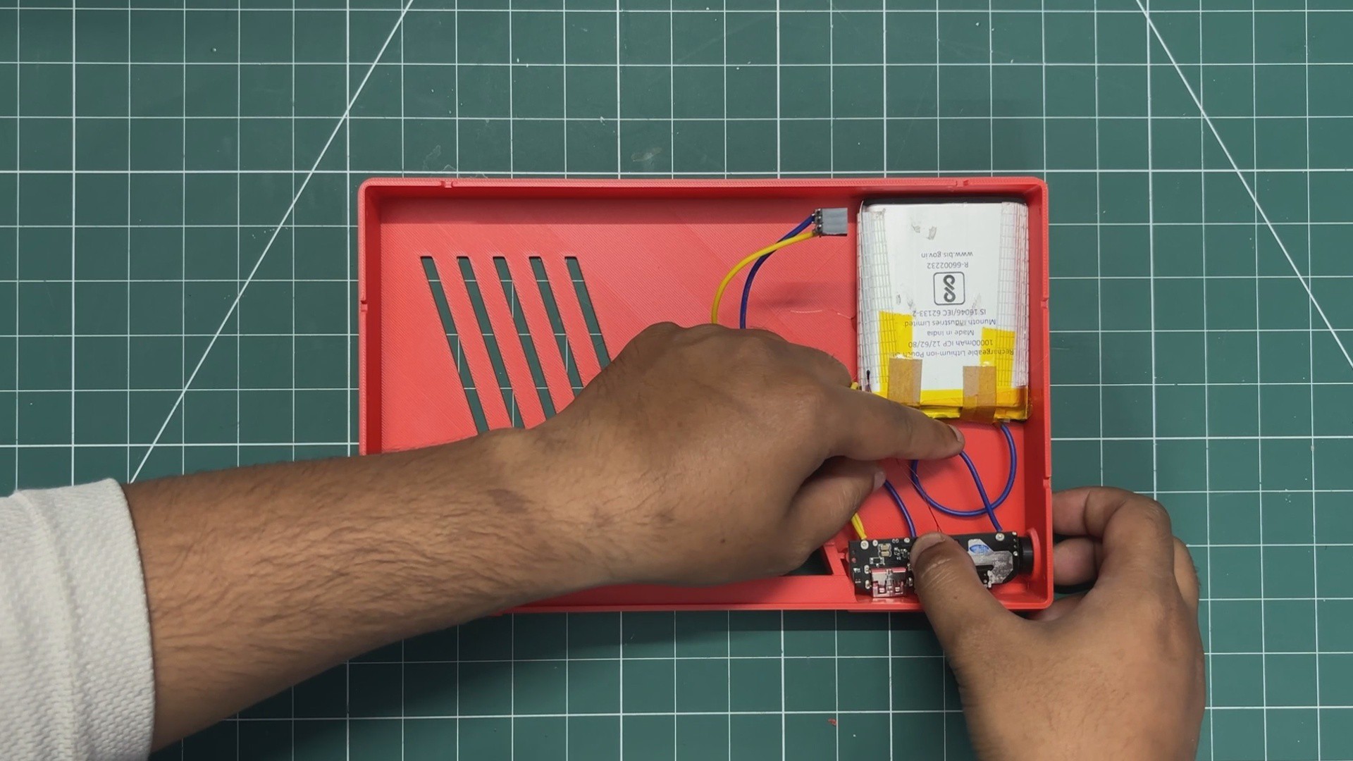
I added some hot glue to the battery placement area and positioned the lithium cell in place. The hot glue keeps the battery securely locked in position.
Next, we added the 3D-printed switch actuator by placing it into the hole provided on the bottom face of the back body.
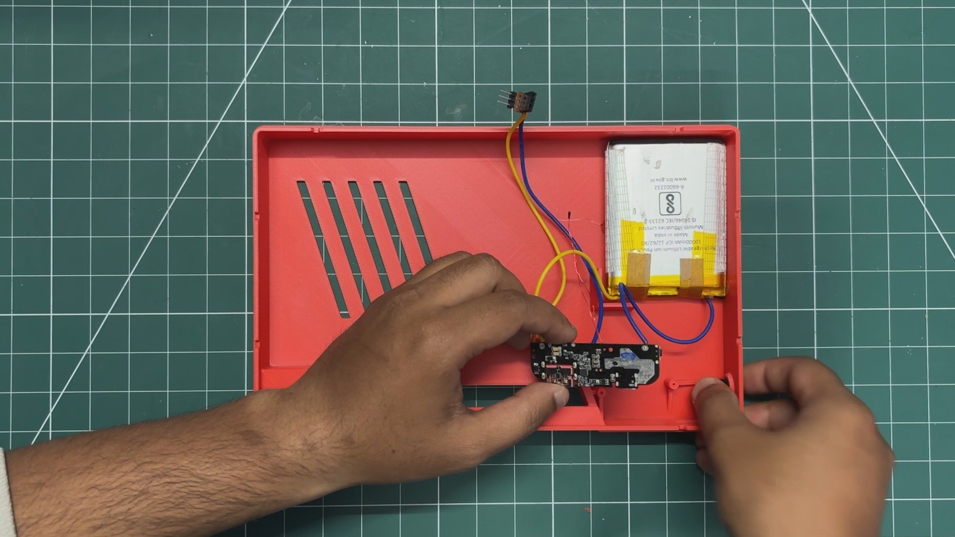
The circuit was then positioned in its designated location. We aligned the circuit's mounting holes with the screw bosses and used two M2 screws to secure it in place.
By doing this, the circuit is now firmly fixed in position. Pressing the switch actuator turns the circuit ON, while holding it for three seconds turns it OFF.
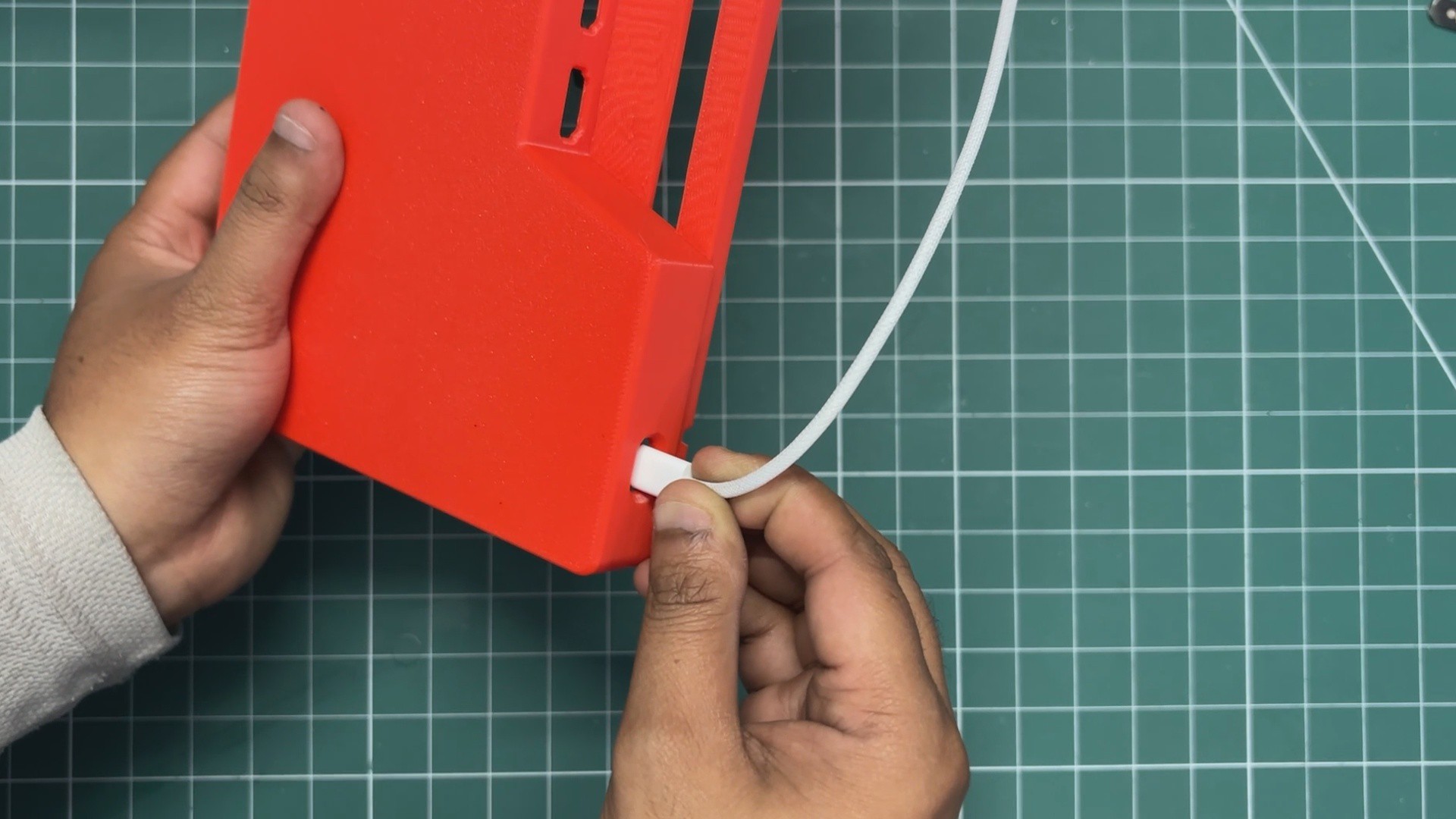
The circuit can be charged using a USB Type-C charger, as the left side of the enclosure includes an opening for accessing the USB Type-C port.
8
ANTENNA ASSEMBLY
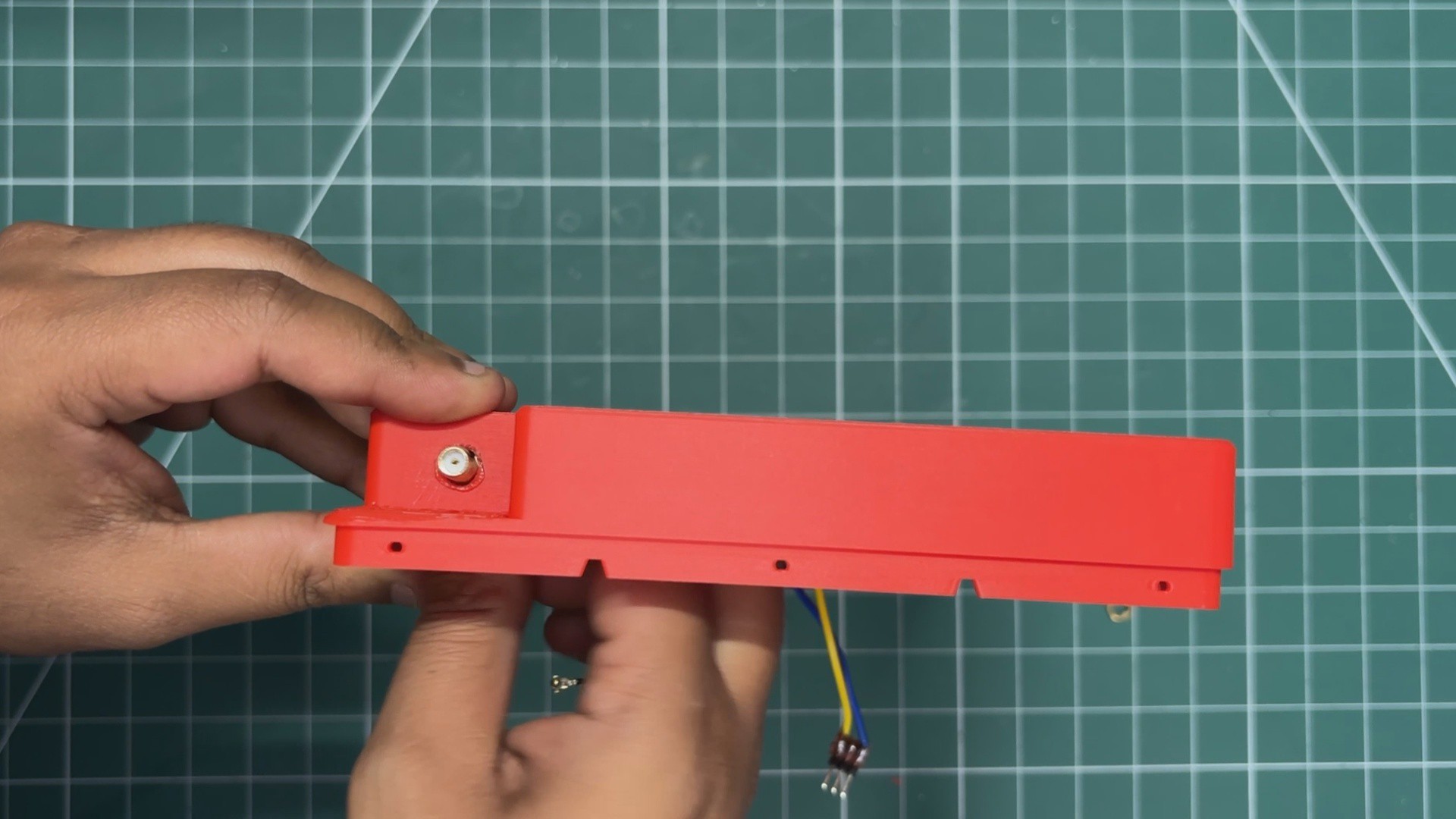
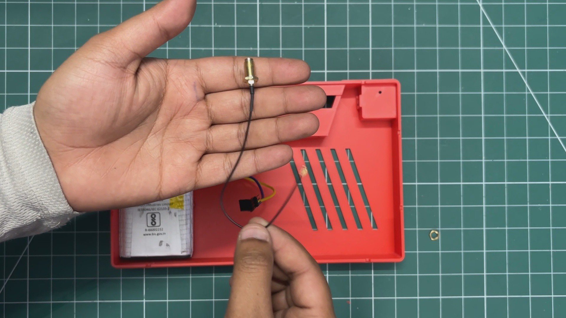
For connecting the Wi-Fi and Bluetooth antenna, we are using an RP-SMA female connector.
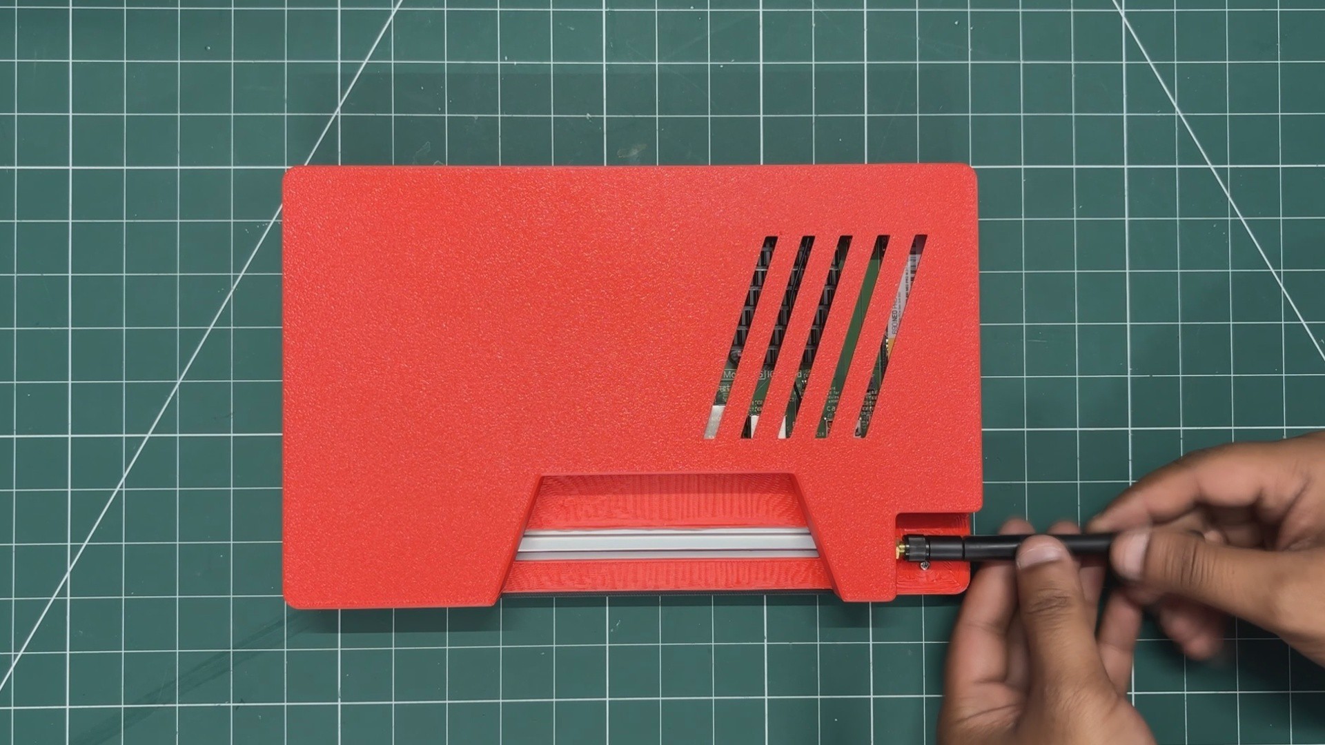
We pass the connector through the hole we modeled at the antenna location on the back body and then tighten the provided nut, which keeps the female RP-SMA connector securely locked in position.
9
FINAL ASSEMBLY
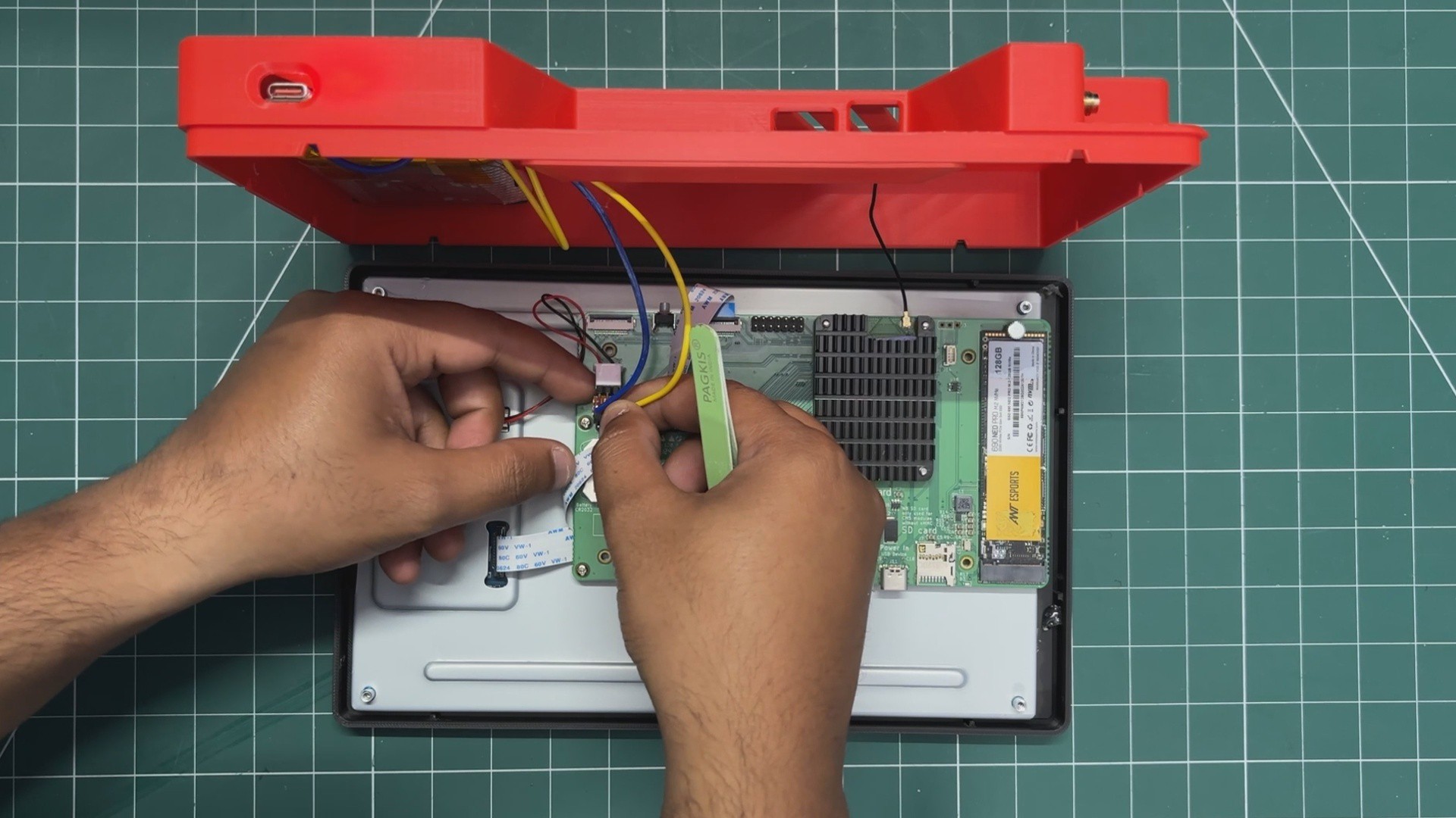
Final assembly begins by connecting the 5V and GND output wires of the power circuit to the Raspberry Pi's GPIO header pins. Doing this connects our power management circuit to the display and CM5 evaluation board.
Next, we connect the U.FL connector of the RP-SMA cable to the CM5's U.FL connector.
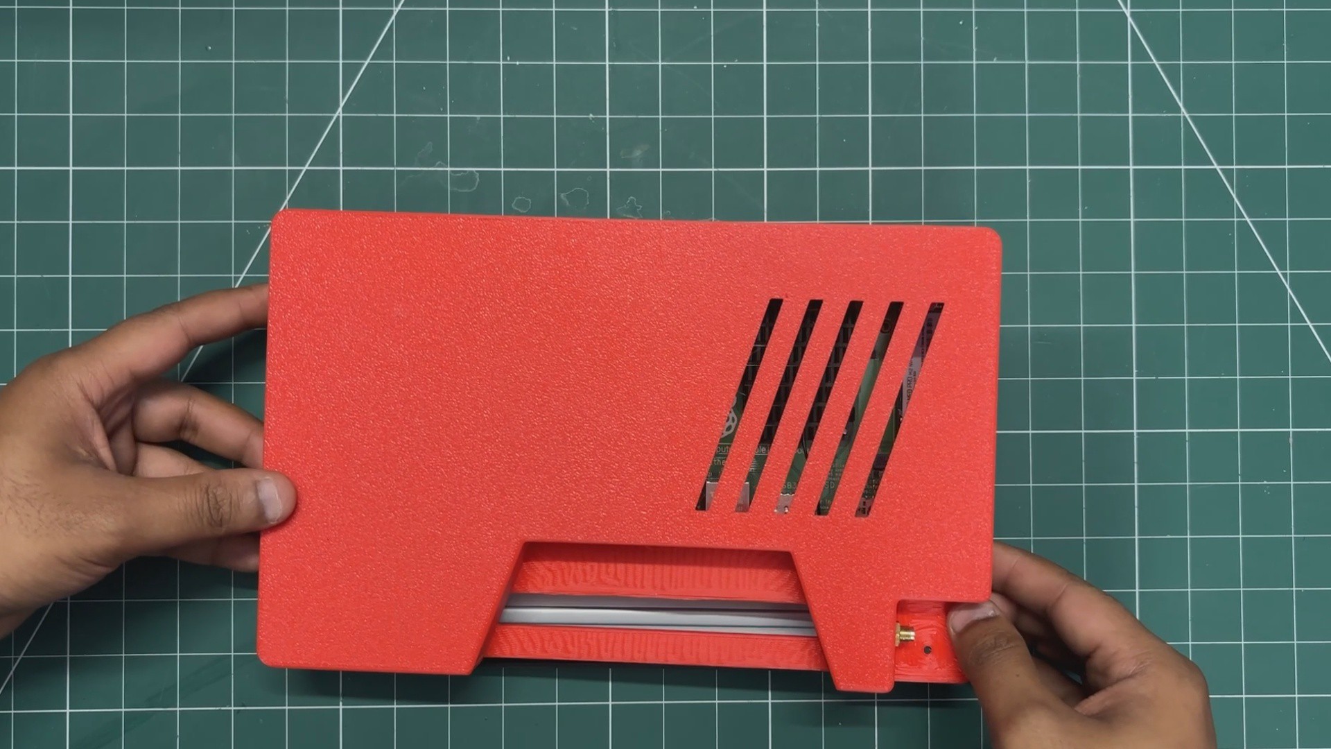
We then position the back body over the frame part and apply gentle pressure, which joins both halves of the enclosure together.
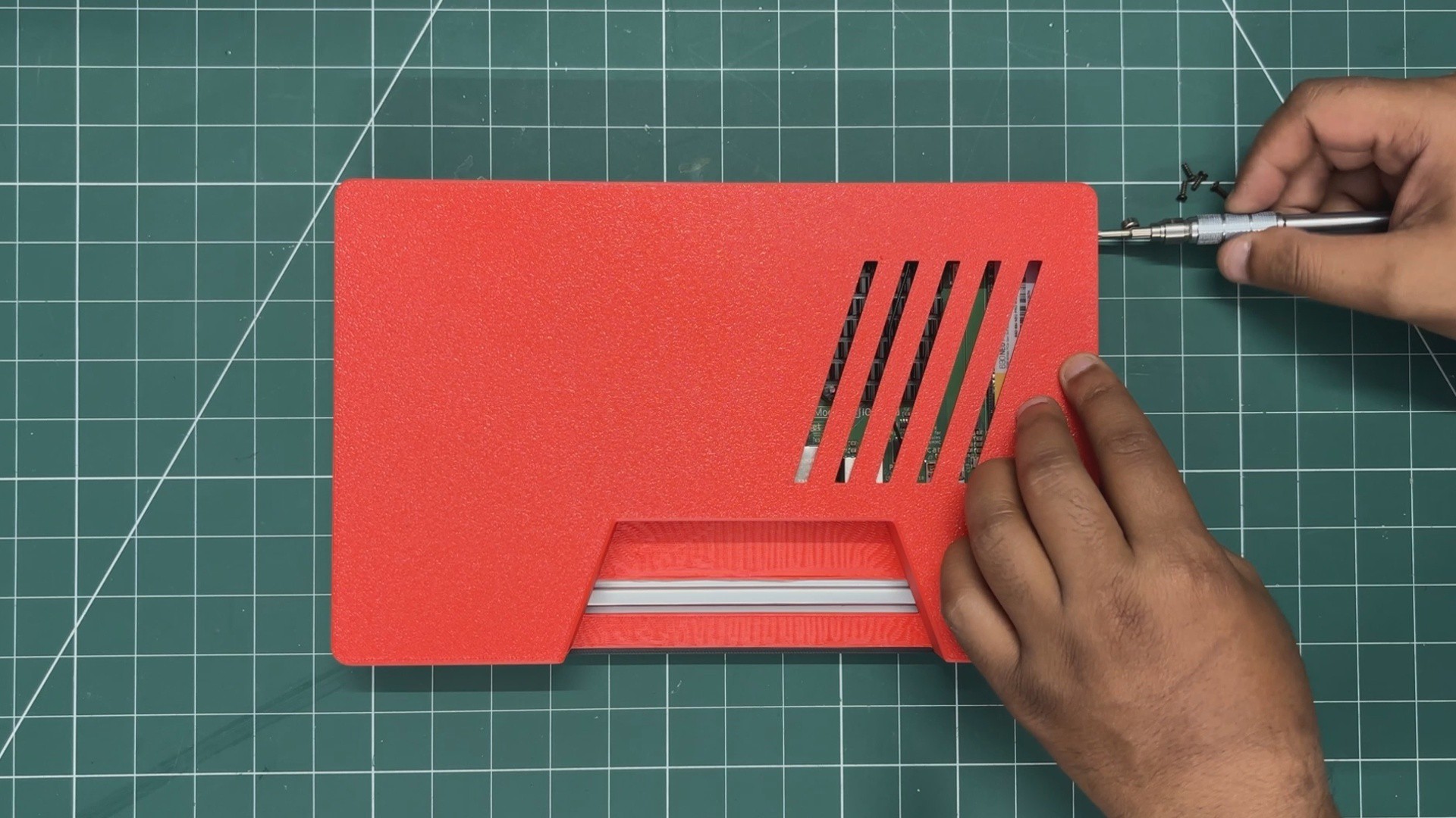
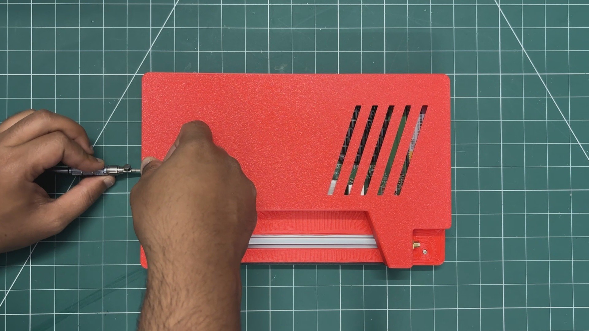
First, we secure the back body to the Waveshare display using a single M2.5 bolt. Then, we install six M2 screws that tighten the back body and frame together—three screws on the top side and three screws on the bottom side. This completely secures the enclosure and locks everything in place.
As a final step, we screw the antenna onto the RP-SMA connector, which completes the assembly process.
10
RESULT
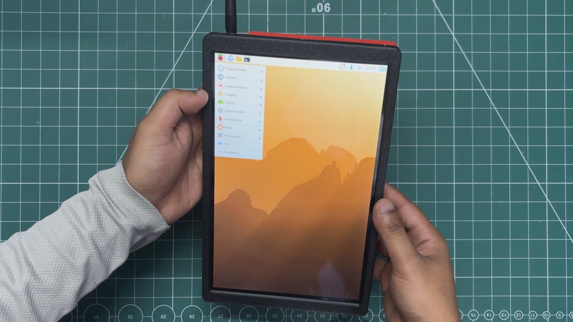
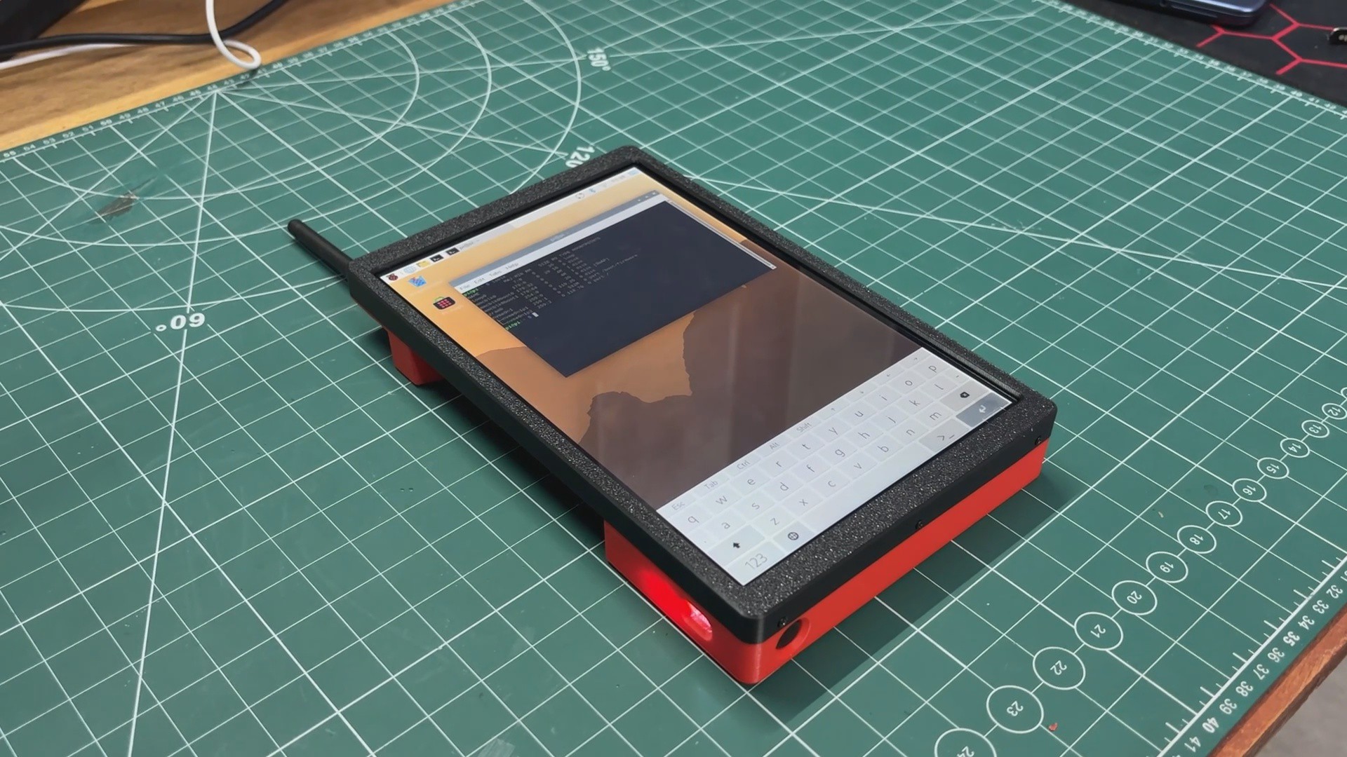
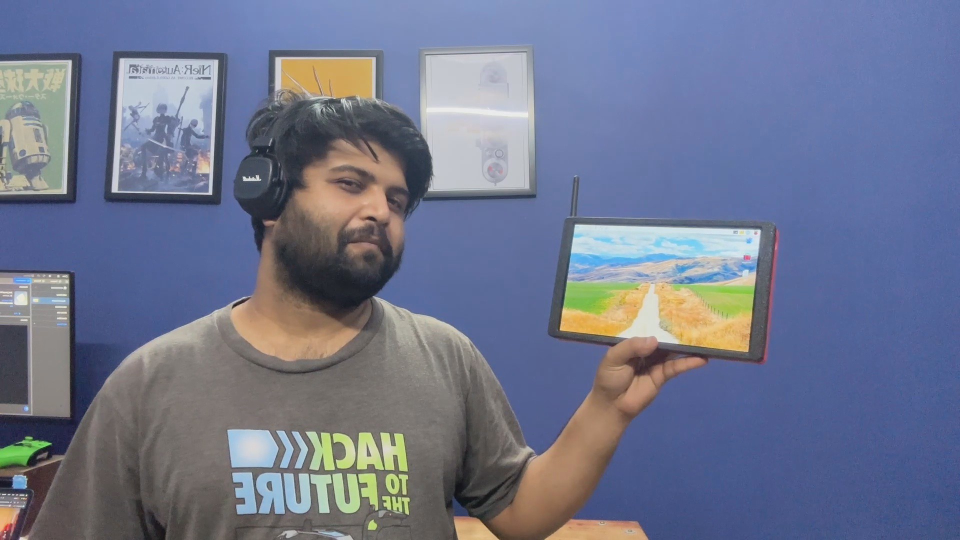
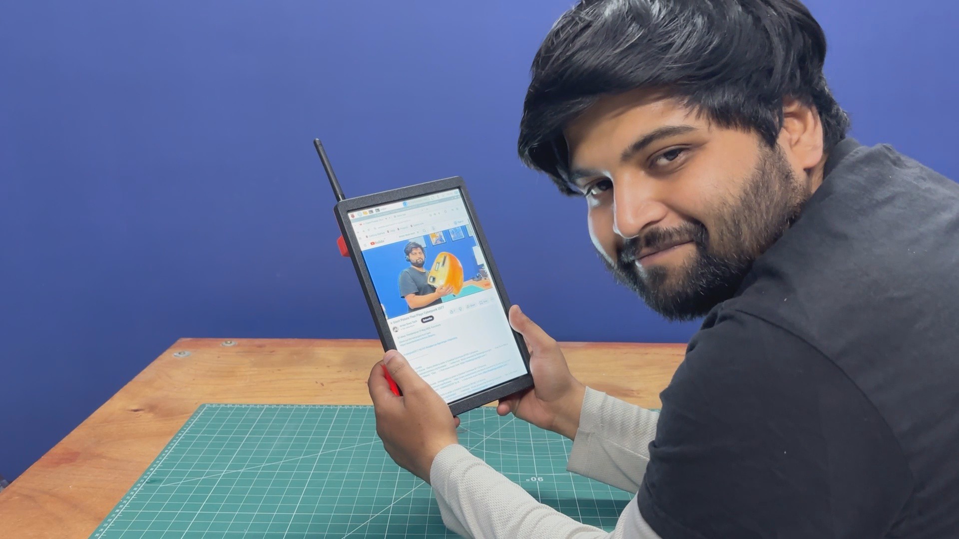
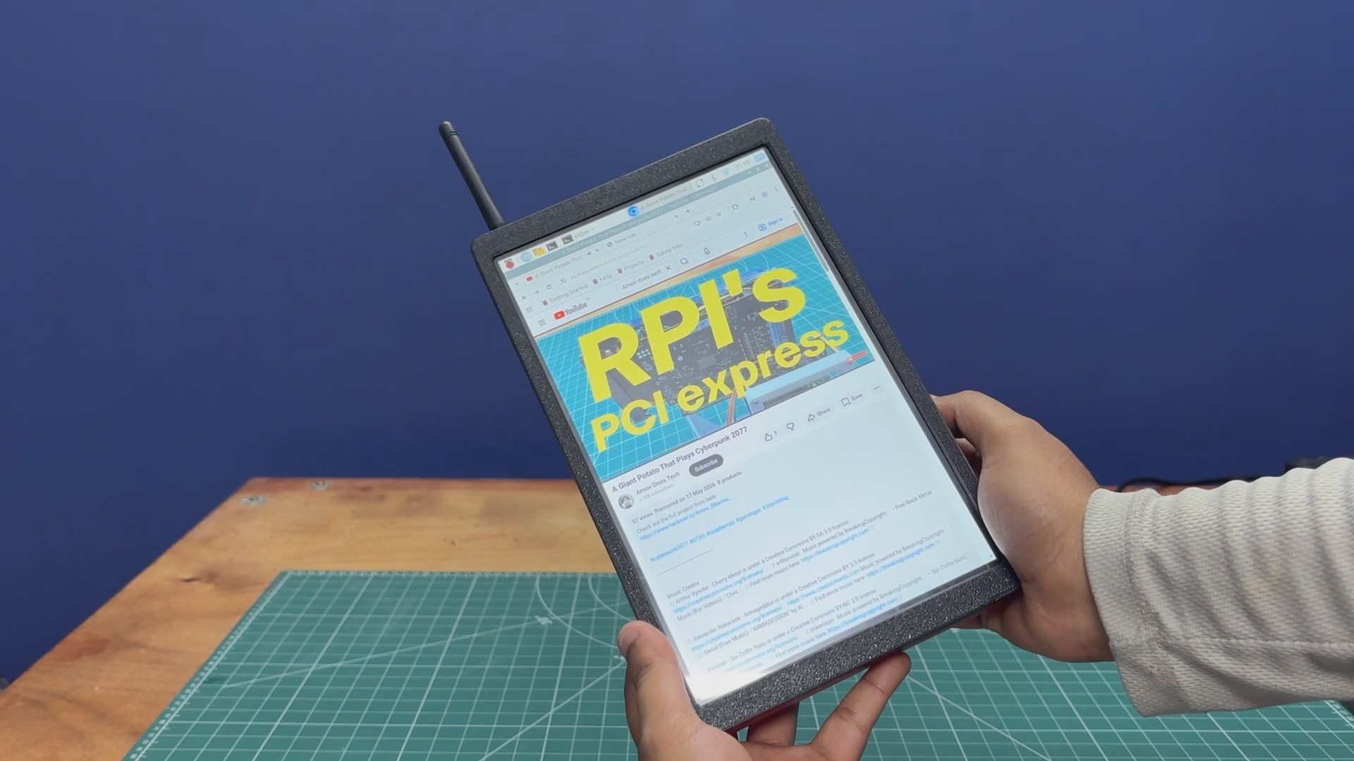
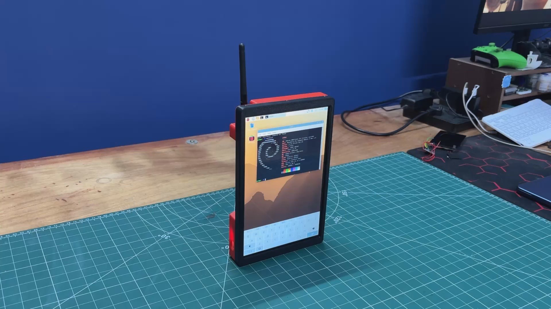
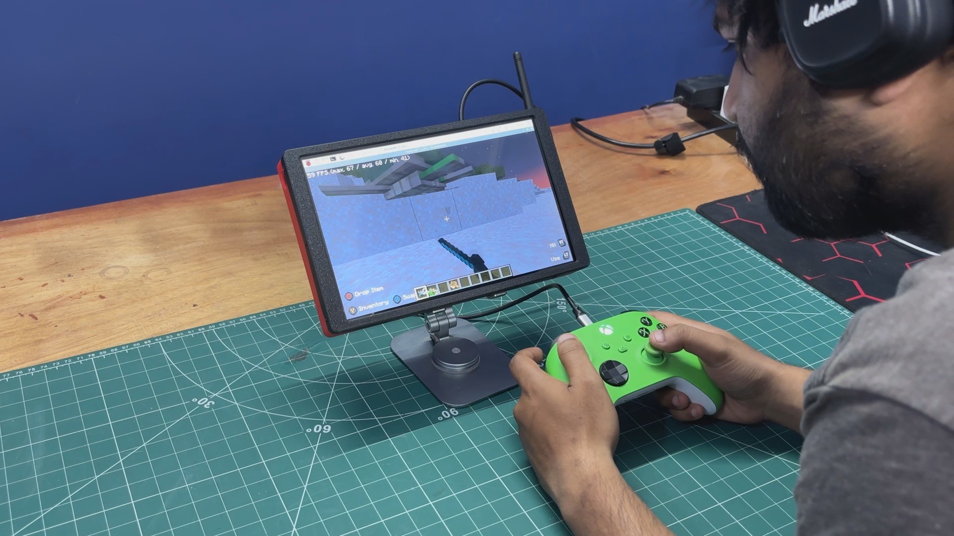
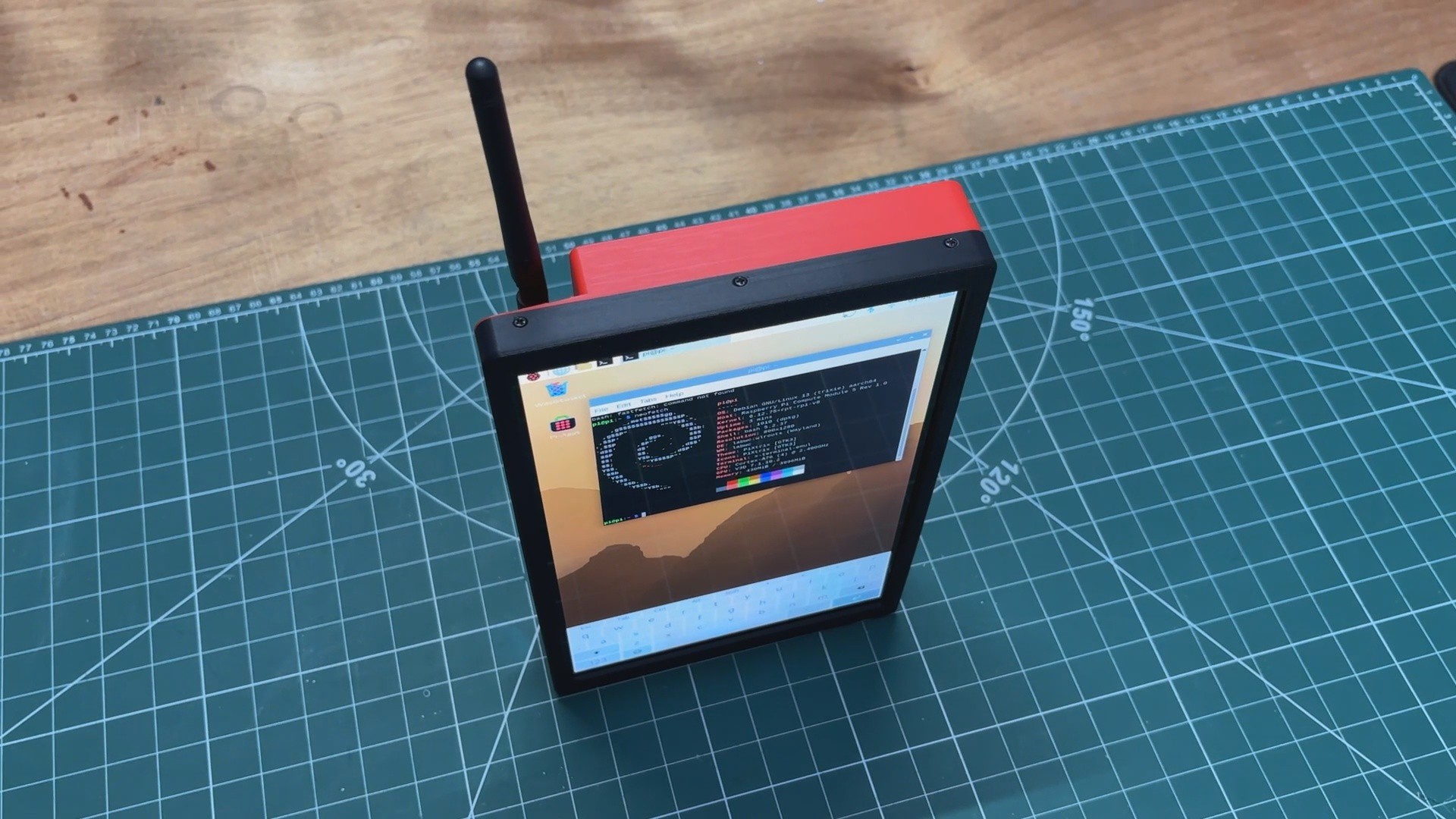
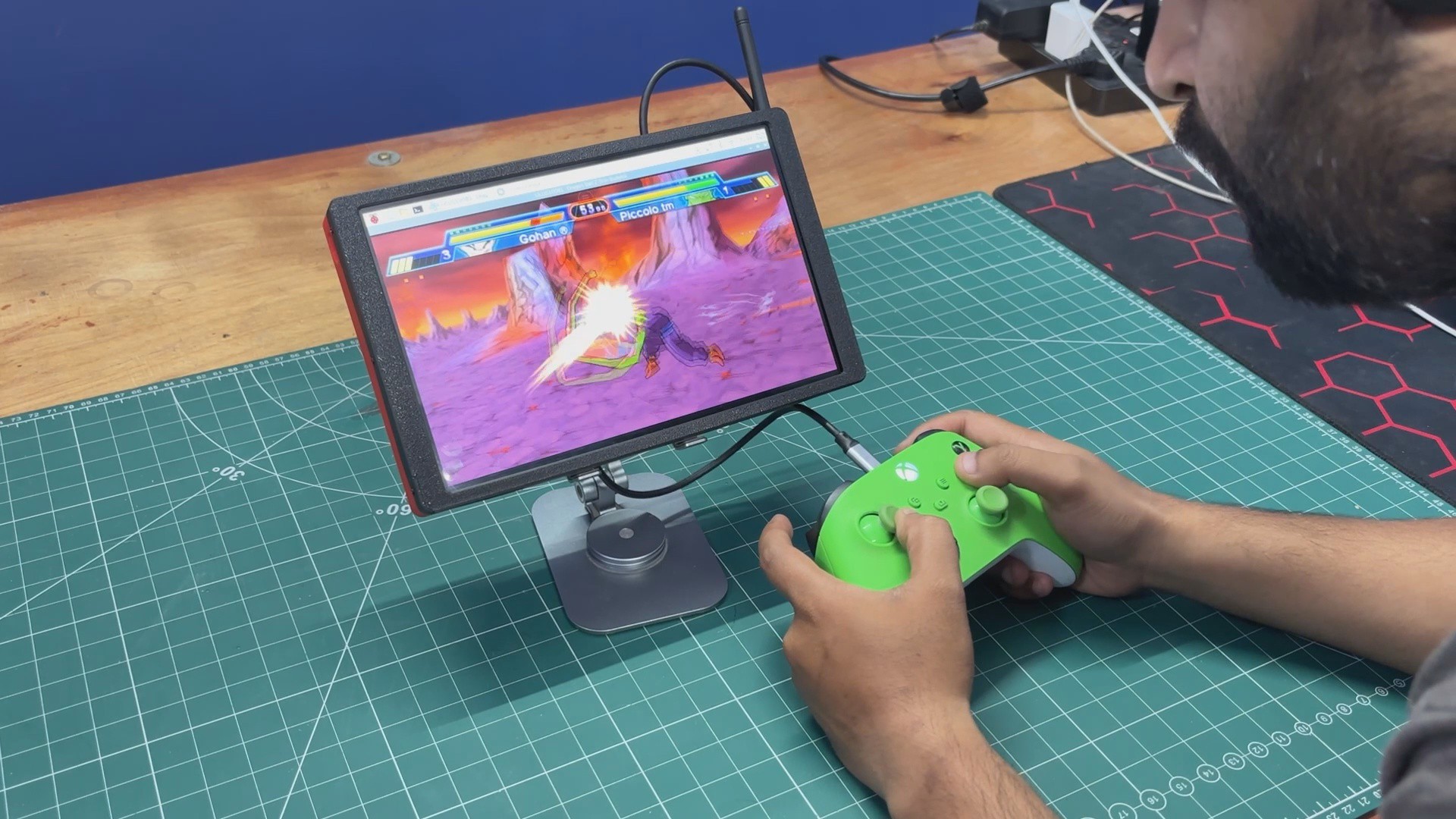
Here's the end result of this project: a tablet, but it runs Linux.
It has an onboard battery, a touchscreen display, and even an antenna that makes the device look like something a hacker would use. Combined with the rugged enclosure, it gives the tablet a robust and industrial appearance.
This tablet is basically exactly what I needed for my upcoming project, which requires a Raspberry Pi computer with a display that I can easily carry from one site to another. It's for a solar-related project that I might publish an article about in the future. With this tablet, I can access the terminal anywhere and use it to connect to and monitor my solar panel setup.
I already own an Android tablet and an iPad. Both are incredible pieces of engineering, but they feel like products made for everyone. This one is different, as it's made specifically for me and my workflow.
That's probably my favorite thing about this build. It's completely DIY and fully open. I can swap the operating system, install whatever software I want, write my own applications, and have full access to the terminal. There are no restrictions, no locked-down ecosystem, just a computer that I built around my own requirements.
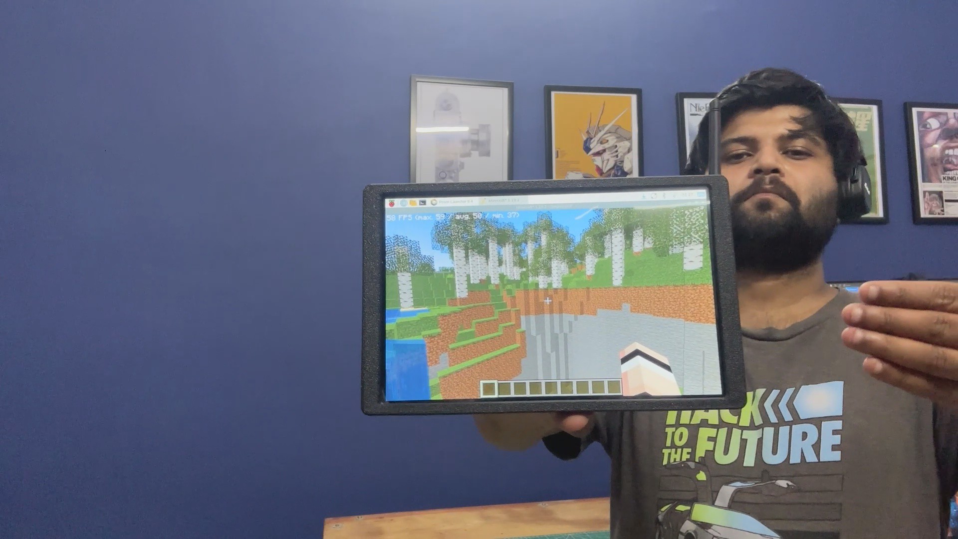
And despite being a DIY project, it's surprisingly capable. I even ran Minecraft Java Edition on it, and thanks to the Compute Module 5, it runs smoothly. The 10-inch touchscreen makes the whole experience feel like a proper tablet, whether I'm working on a project, browsing the web, watching videos, or just experimenting with new ideas.
At the end of the day, this project wasn't about building a tablet. It was about building the exact tool I needed. A portable Linux workstation that I can throw in a bag, take anywhere, and modify whenever I want.
And honestly, that's what makes DIY hardware so rewarding. You don't have to buy the perfect device. You can build it yourself, customize it yourself, and shape it around your own needs.
 Arnov Sharma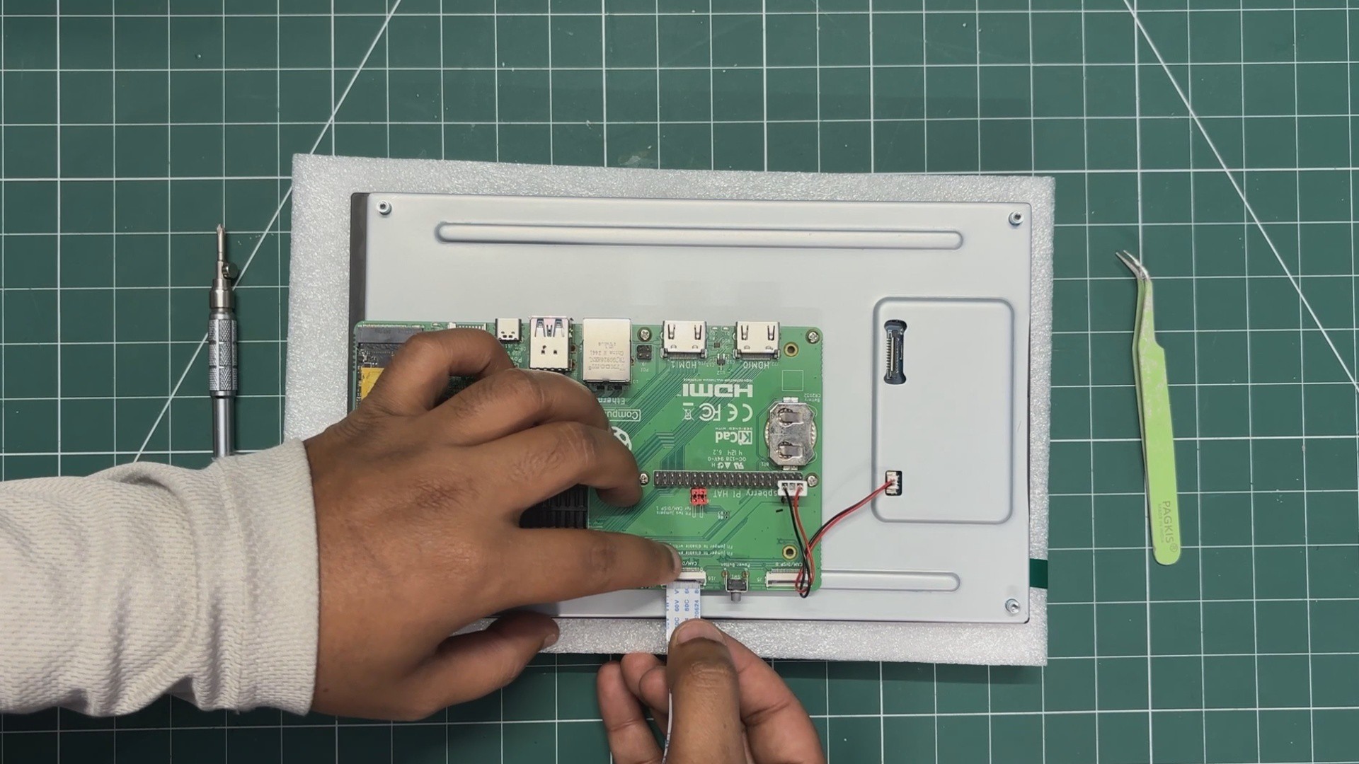
Discussions
Become a Hackaday.io Member
Create an account to leave a comment. Already have an account? Log In.