 Arnov Sharma

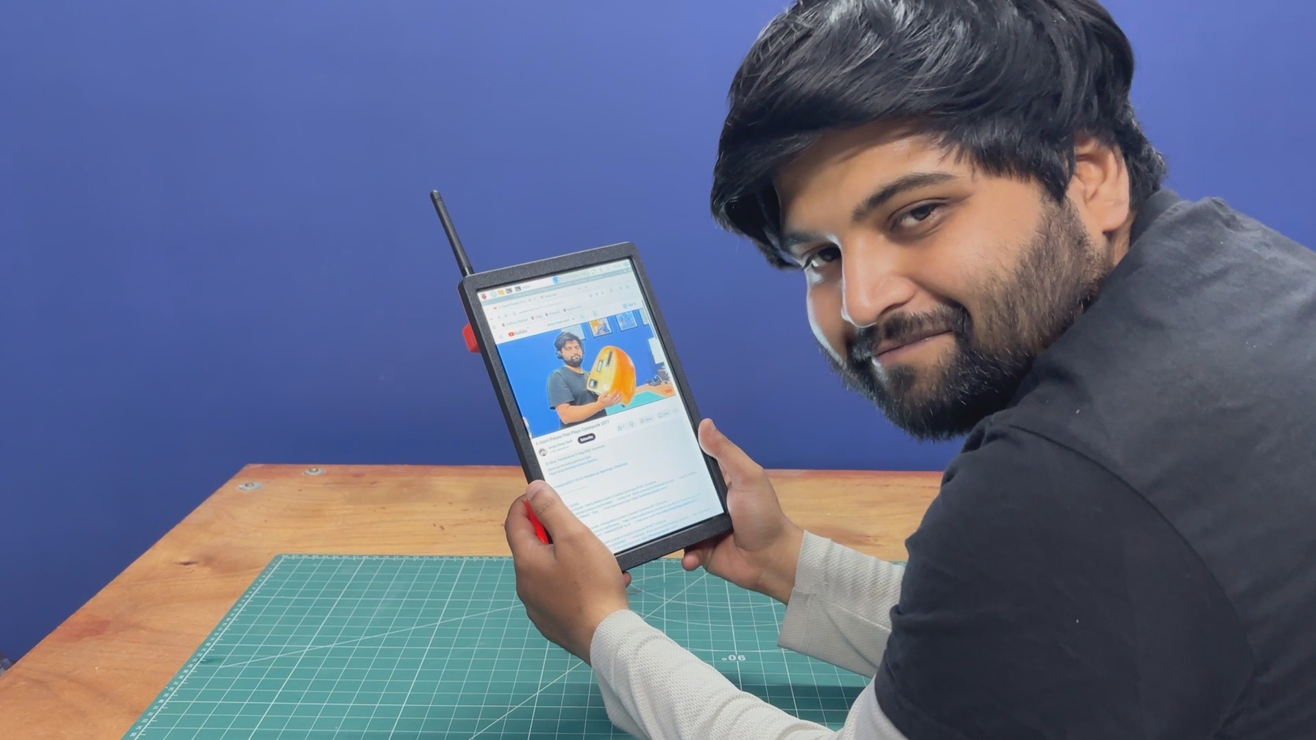
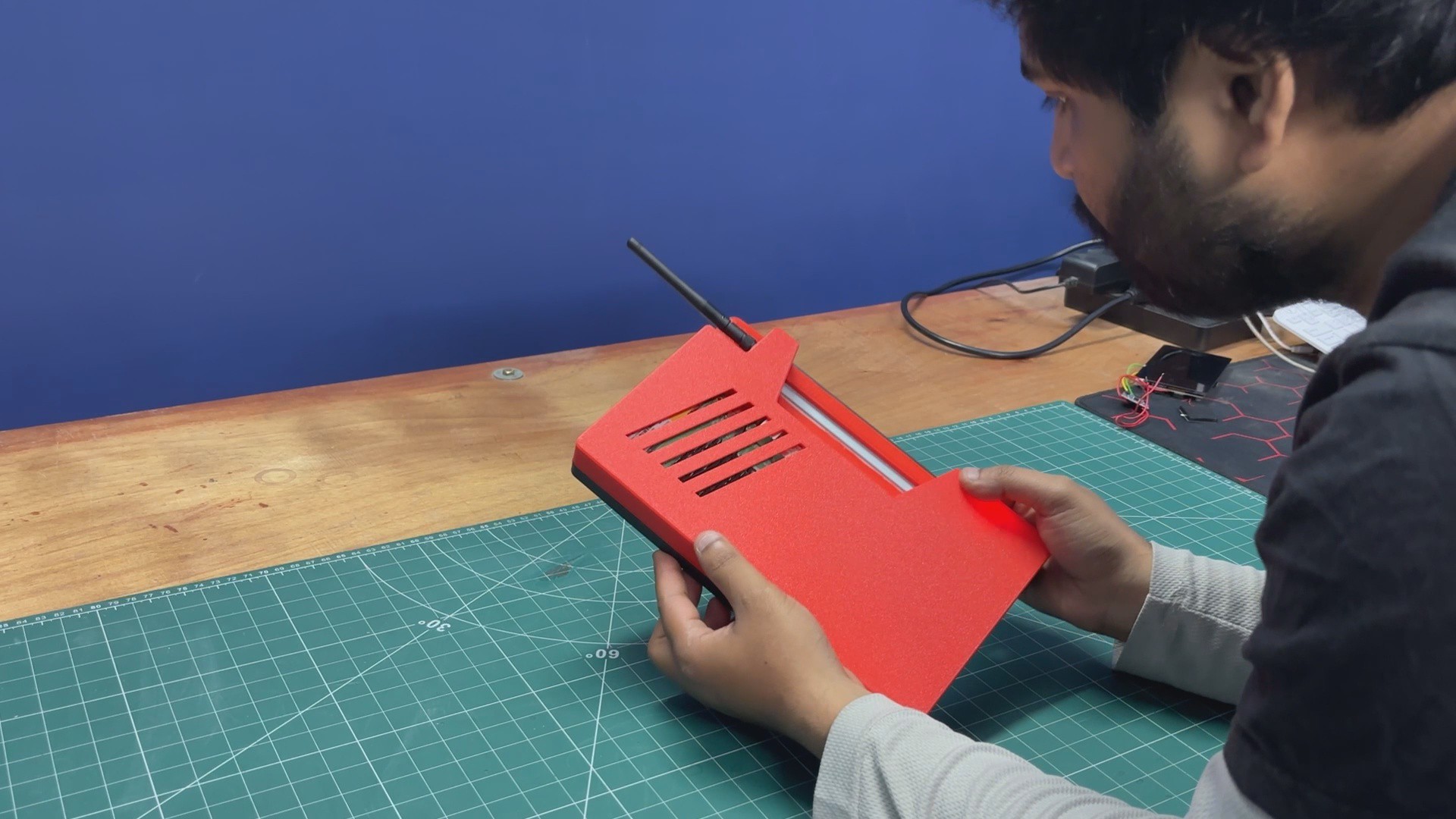
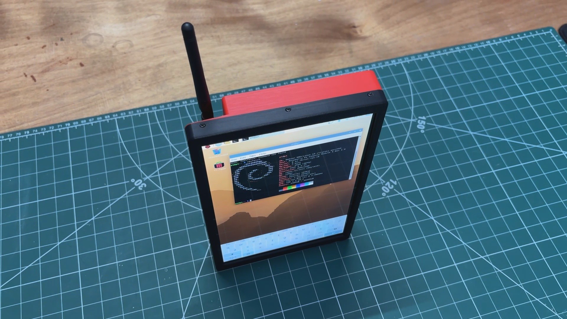
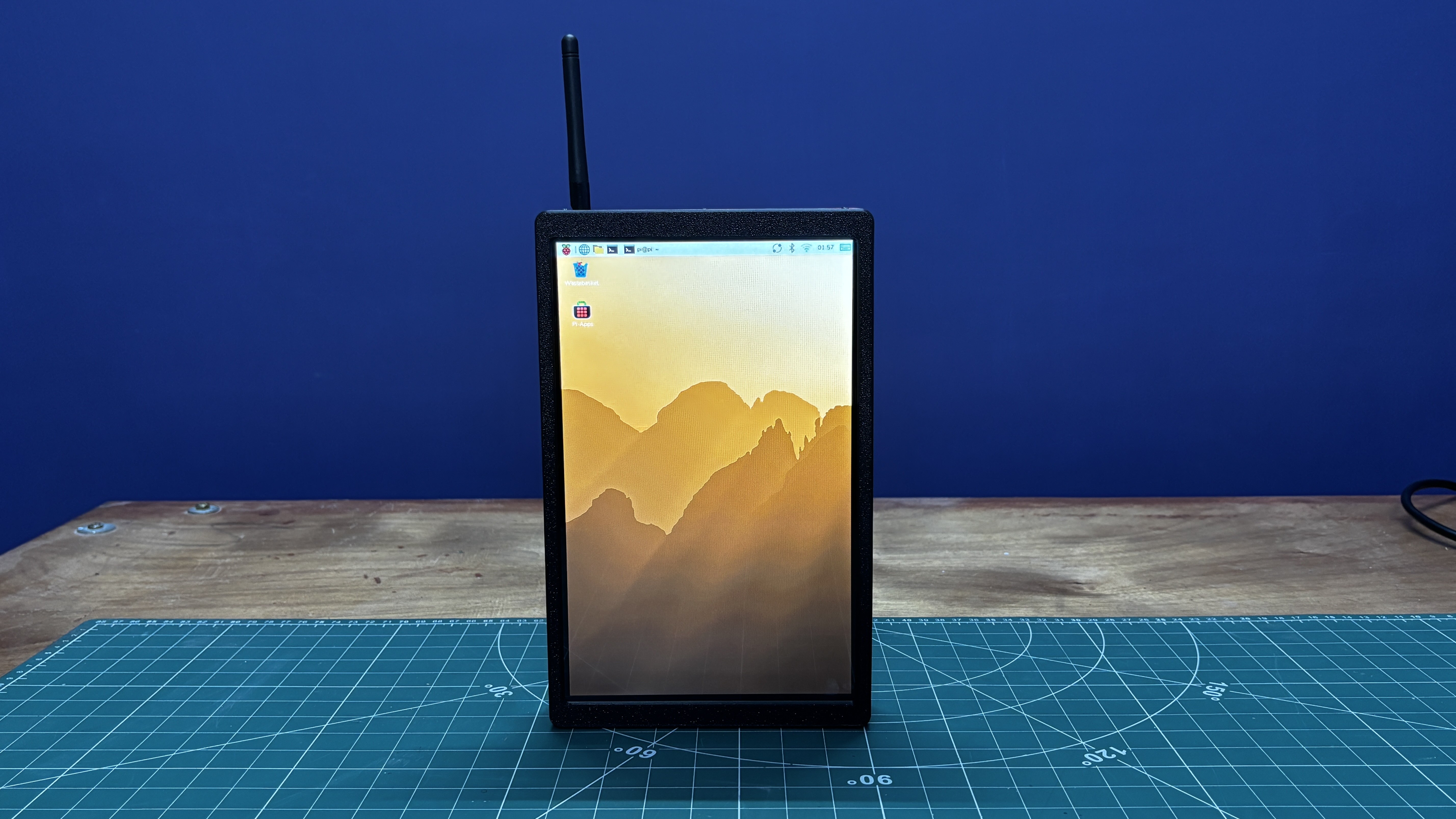
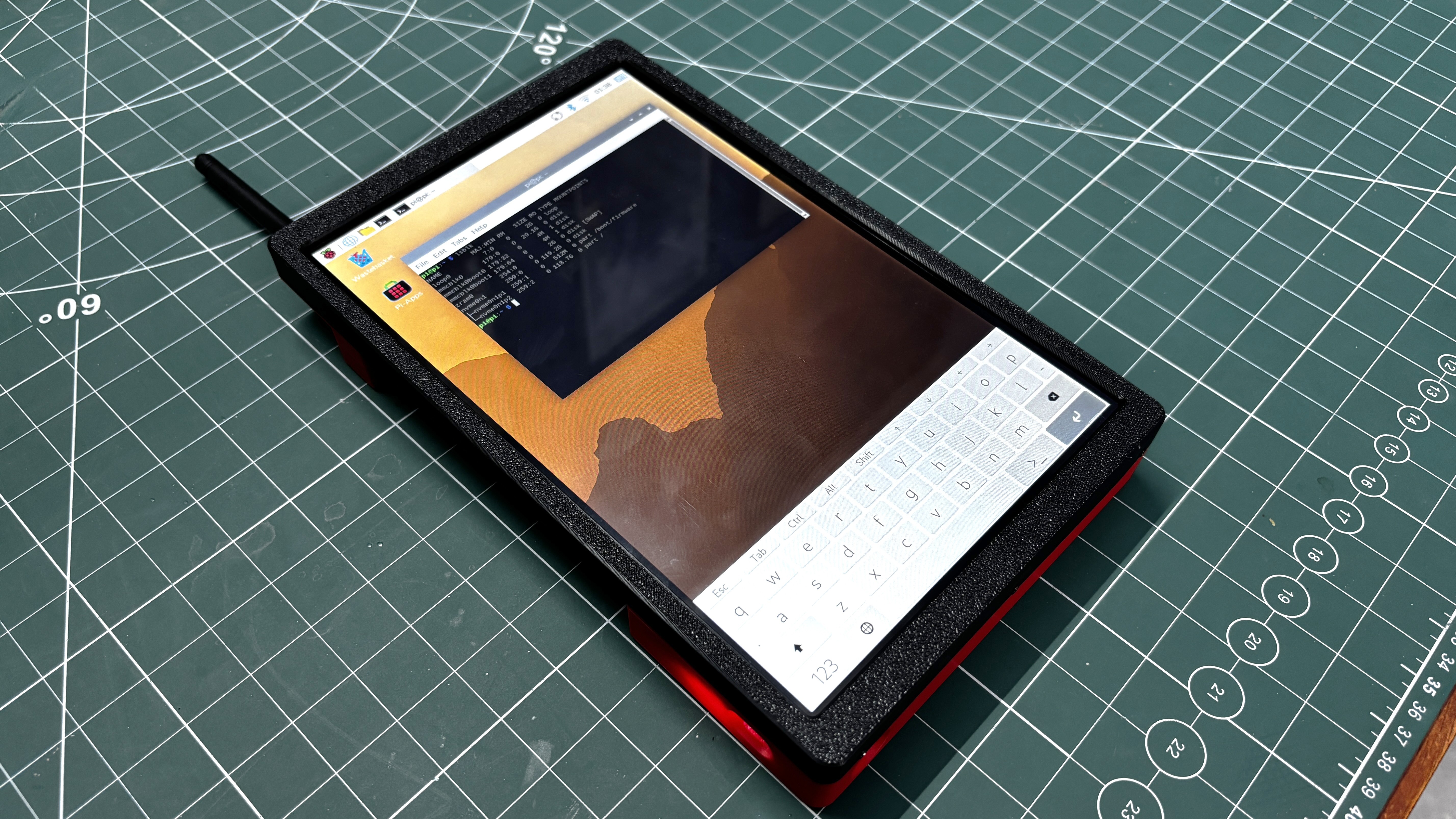
The goal of this project was to create a portable Linux tablet for an upcoming solar project, where I needed a device that I could easily carry from one site to another while working outdoors. A laptop could have been used instead, but I wanted something more portable and convenient to work with. Raspberry Pi OS is perfect for this task, which is why I decided to build a tablet around the CM5 and a touch display.
This Device is a fusion between a touch computer and a tablet. I have used a 4GB variant of the CM5, and for improved performance, I installed the operating system on an NVMe SSD, making the system super fast.
To enhance Wi-Fi and Bluetooth connectivity, I also added an external antenna to the device.
I designed the enclosure in Fusion 360 and printed the parts on my 3D printer in two colours to get a duotone aesthetic.
This article covers the complete build process of the tablet, so let's get started with the build.
IDEA
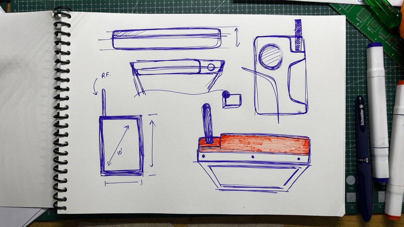
The whole idea came from the fact that I needed a Linux system—a portable Linux system that would help me with a solar monitoring project I'm working on. I had already been using a Raspberry Pi 4 in that project and needed a device that would allow me to SSH into the setup and monitor the solar cells on the go.
A laptop could have been used for this purpose, but I wanted something more portable, like a tablet that runs Linux. I did a quick Google search and found very few Linux tablets available, so I decided to build one myself since the concept was quite simple.
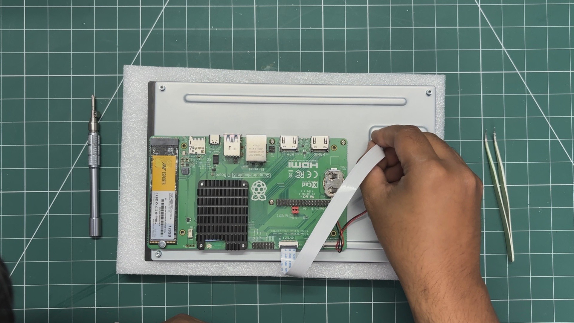
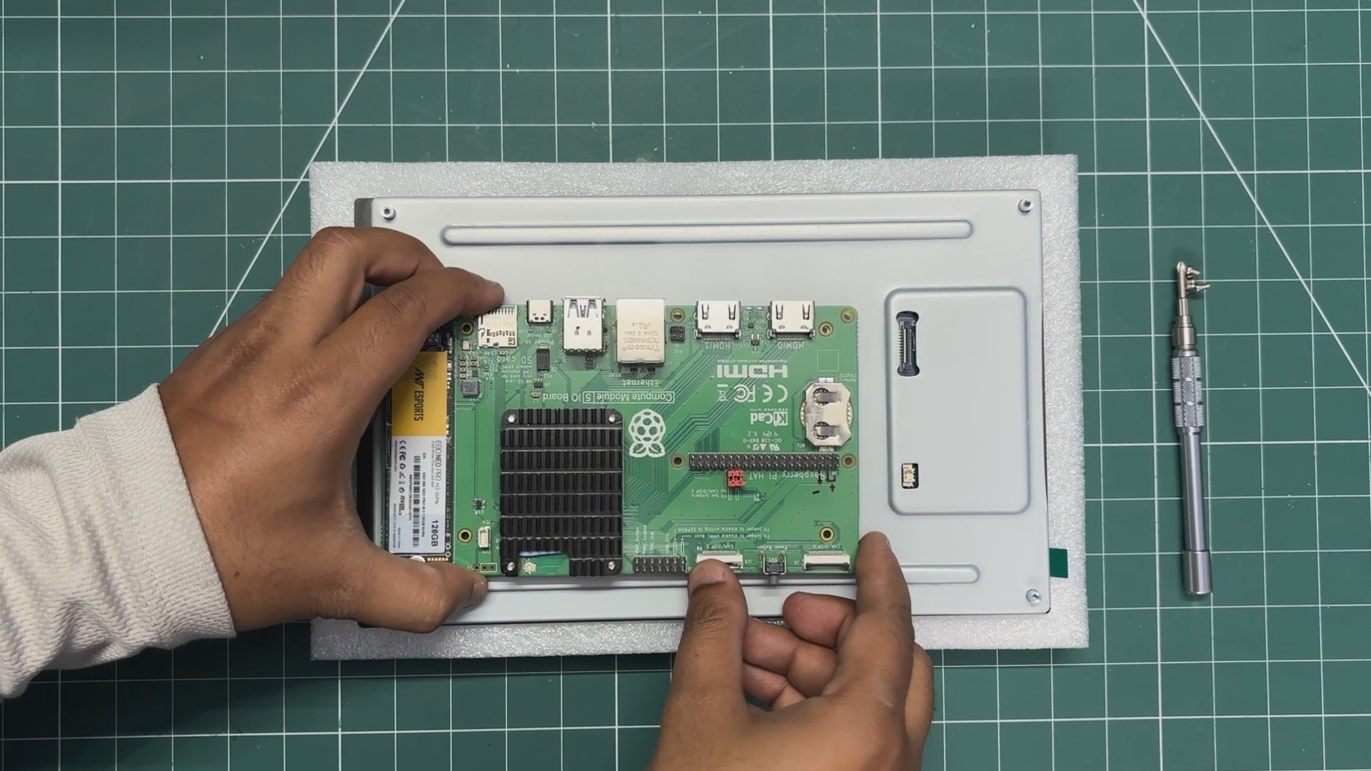
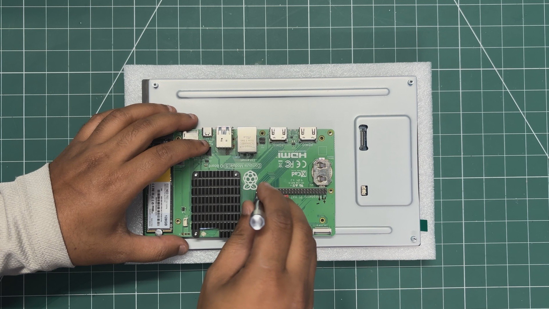
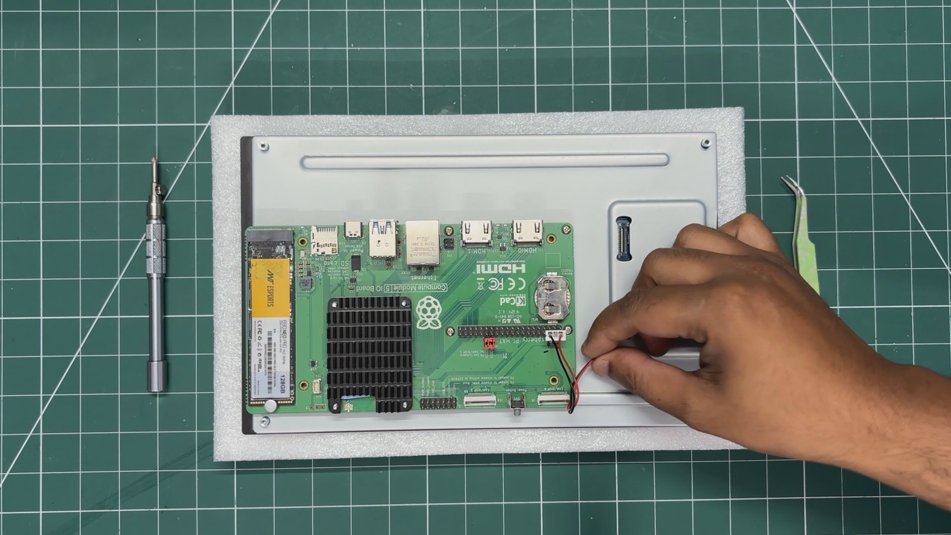
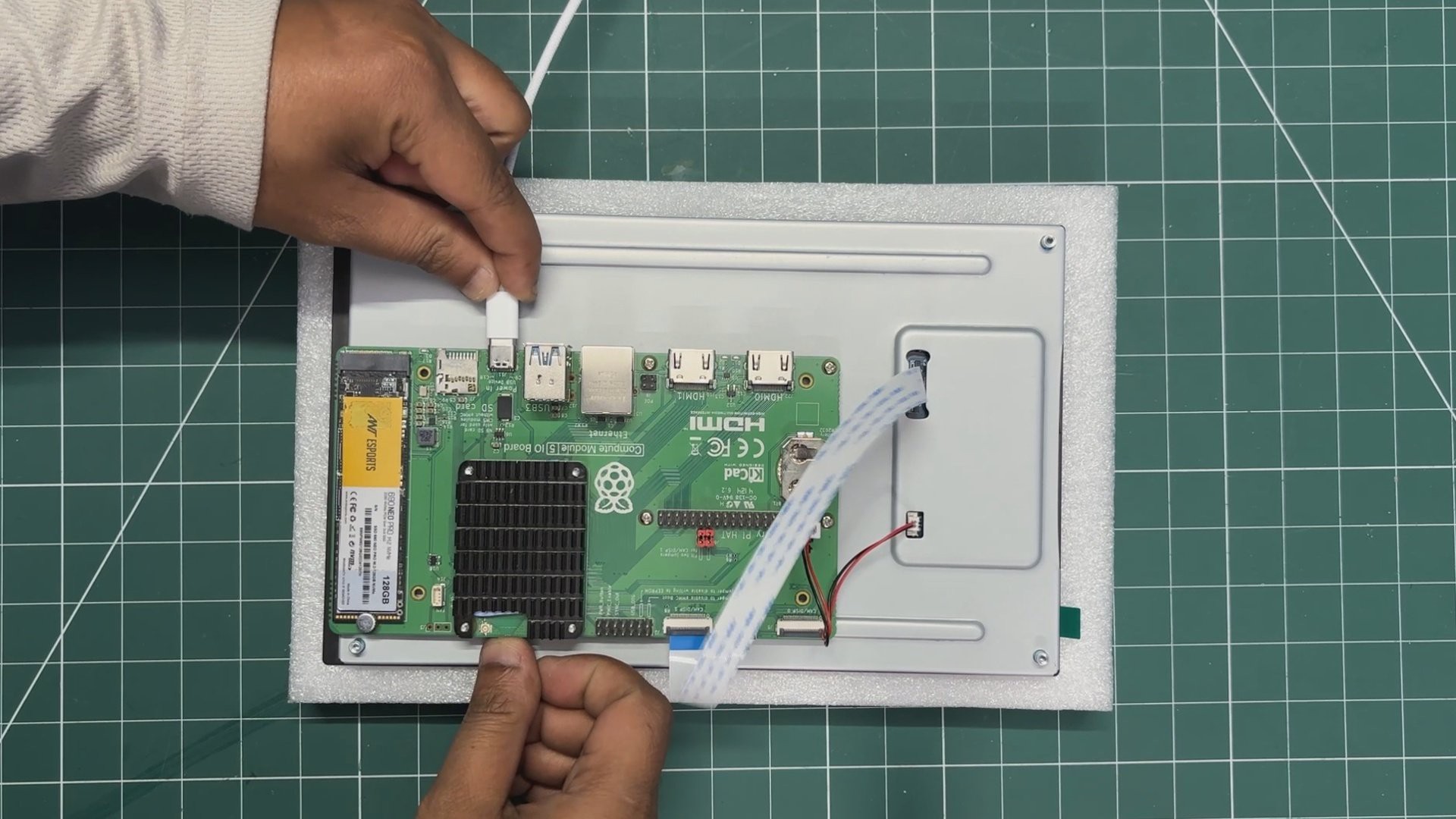
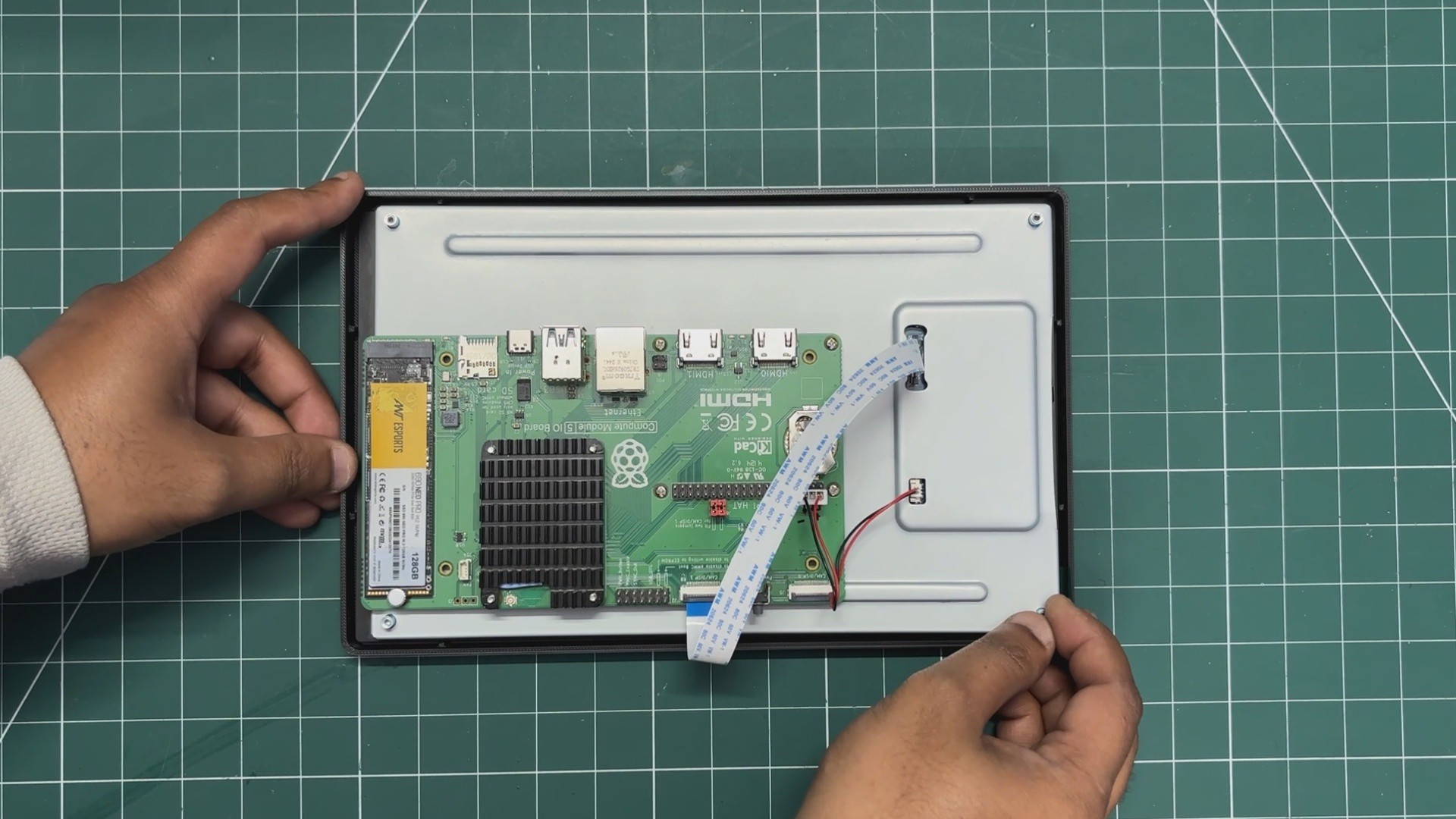
The project only needed three main components: a small computer, a display, and a battery source. For the computer, I selected the Raspberry Pi Compute Module 5 along with its full evaluation board. For the display, I used a Waveshare 10-inch DSI touchscreen that I already had, which turned out to be perfect for this project. Finally, for power, I repurposed a MagSafe power bank by completely stripping it down and using its battery and charging circuitry inside the tablet.
HARDWARE- WAVSHARE 10.1 INCH DSI SCREEN
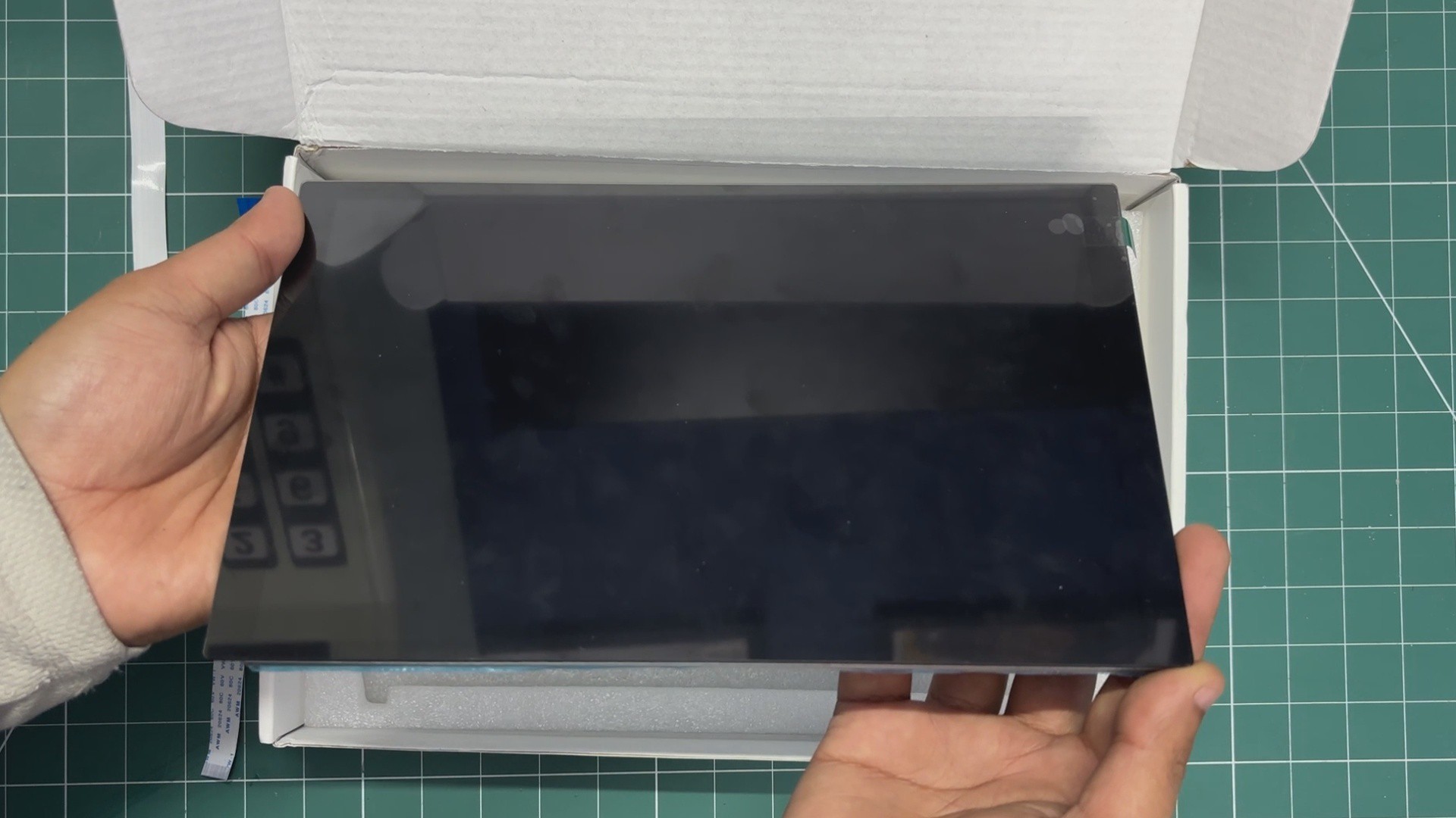
For the main display, I wanted something huge, not the average 7-inch size, but something larger.
Connectivity was also an important factor, as I wanted a DSI interface instead of HDMI.
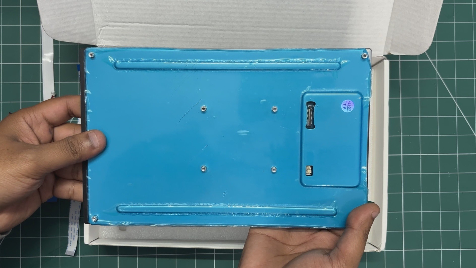
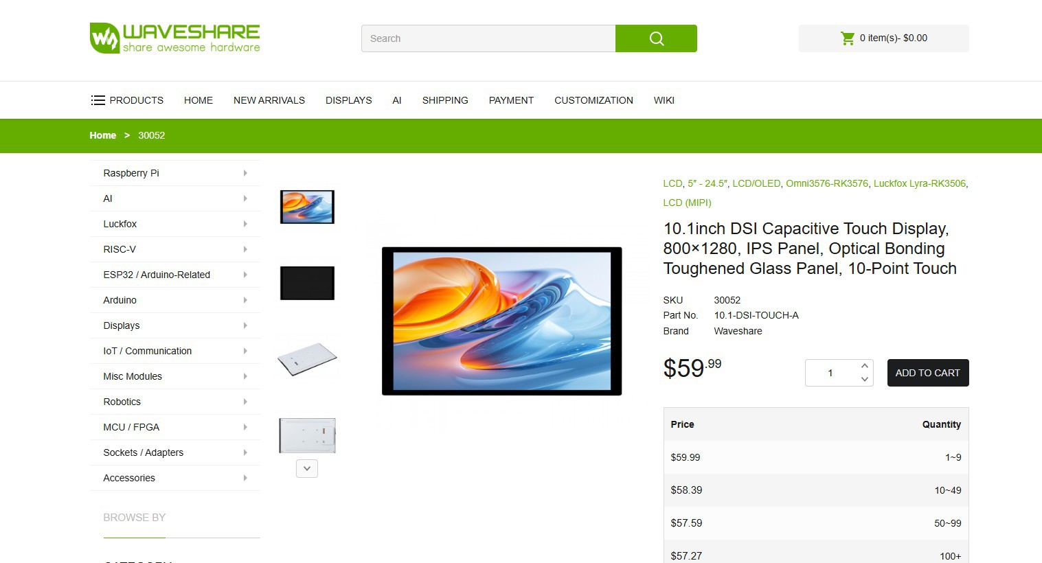
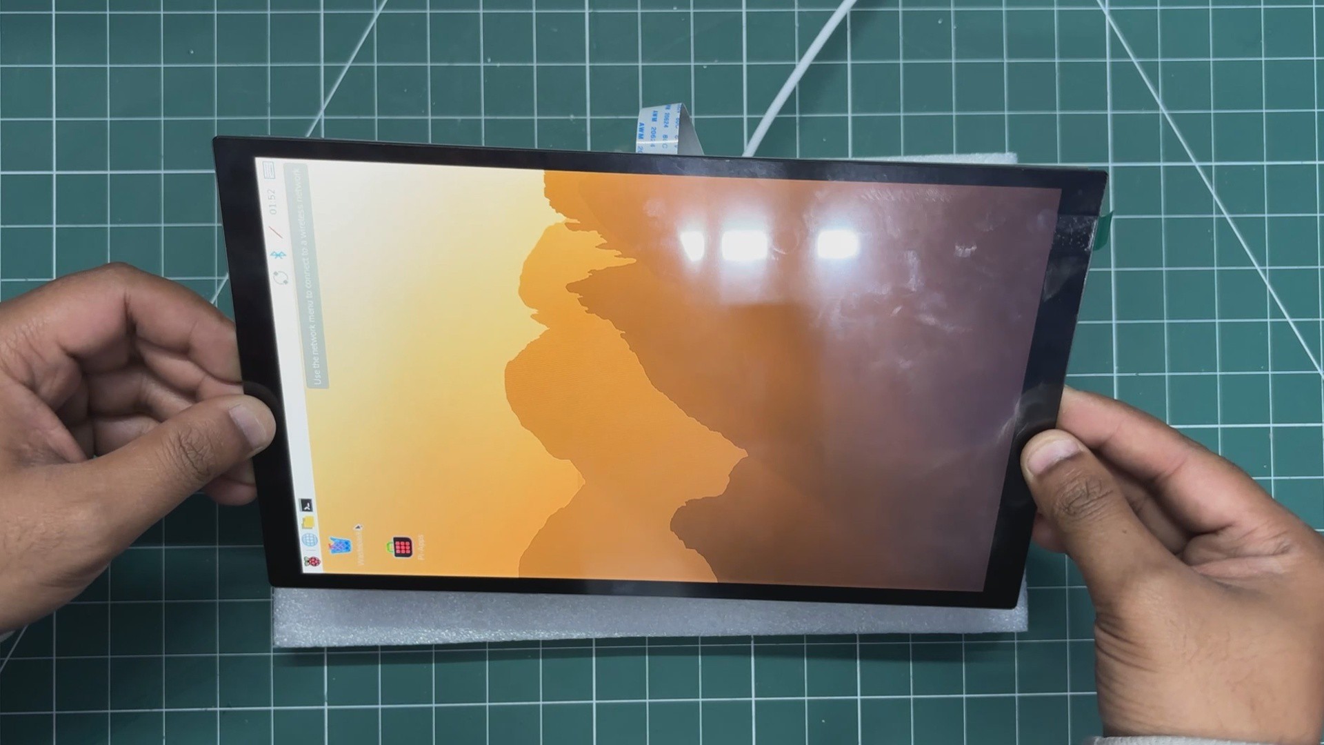
So, I selected Waveshare's 10.1-DSI-TOUCH-A display for this project. It is a portrait touchscreen LCD display with ten-point capacitive touch control. The display uses an IPS panel with a hardware resolution of 800×1280, which is perfect for our tablet application.
The LCD pairs with the Raspberry Pi through the DSI interface and supports a refresh rate of up to 60 Hz, which is more than enough for this application.
The kit comes with two FFC cables for pairing the display with a Raspberry Pi 5 or CM5, one FFC cable for pairing with a Raspberry Pi 4, a power cable, and a couple of PCB standoffs.
You can check out more about this display from its wiki page.
https://www.waveshare.com/10.1-dsi-touch-a.htm?&aff_id=Arnov
http://www.waveshare.com/wiki/10.1-DSI-TOUCH-A
WAVESHARE SERVICE
Special thanks to Waveshare for providing the hardware used in this project. The 10.1 Inch DSI screen and supporting accessories were supplied as review units for testing and evaluation.
Waveshare is a leading global provider of electronic components, modules, and development tools used across robotics, IoT, automation, education, and many other fields. With a strong focus on quality, reliability, and continuous innovation, Waveshare has earned the trust of engineers, designers, hobbyists, and makers worldwide.
Their extensive product lineup, from displays and HATs to expansion boards and embedded modules, makes them a go-to choice for both professional builds and DIY projects.
RASPBERRY PI CM5
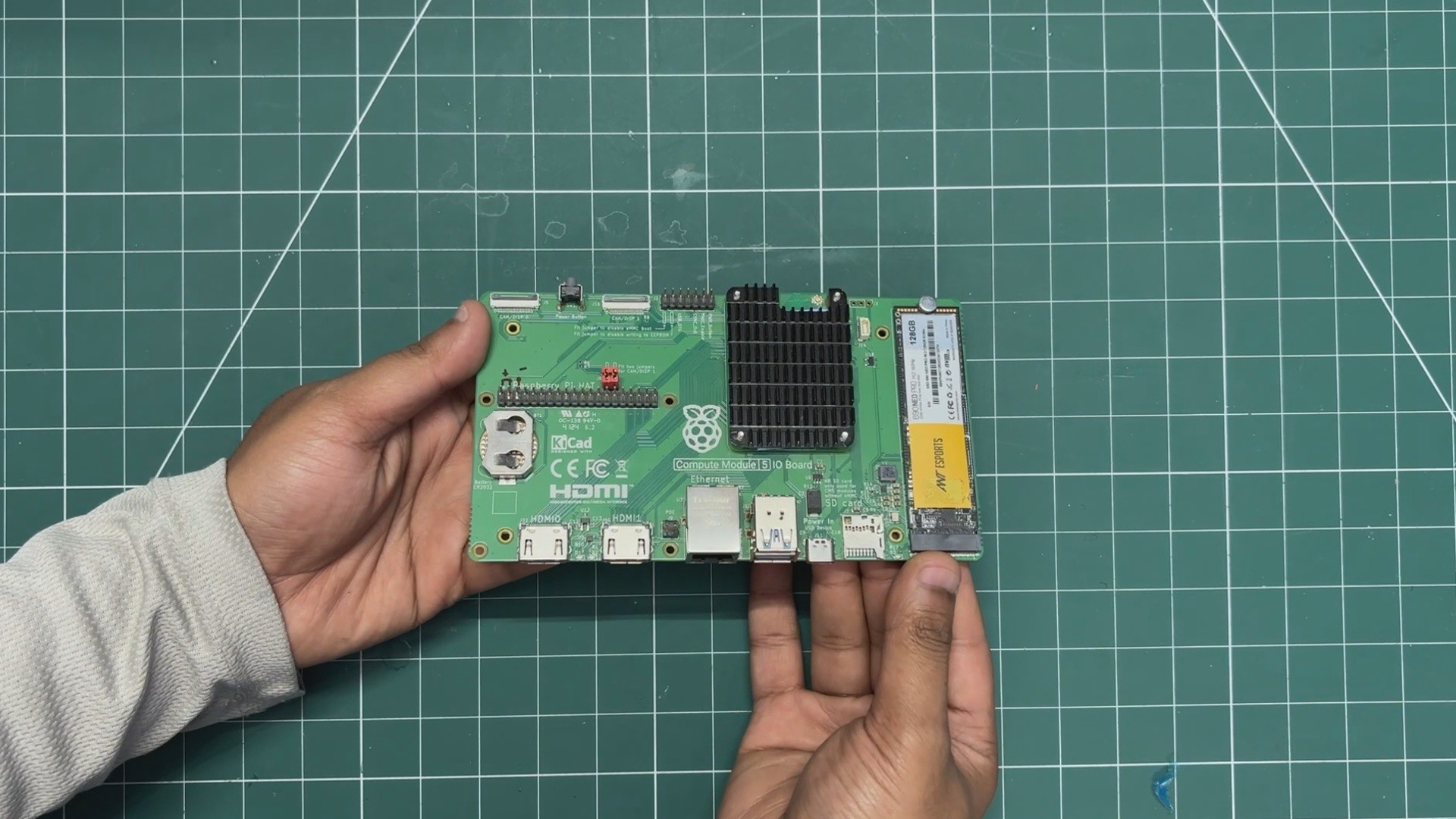
The brain of our project is the Raspberry Pi CM5, which is a more industrial-oriented version of the usual Raspberry Pi 5 in a module form factor. It uses the same Broadcom BCM2712 quad-core 64-bit Arm Cortex-A76 (Armv8)...
Read more »

 hurðaskellir
 Liam Z. Charles