 Doruk Kumkumoğlu
Optocam Zero is a fully open source, pocket sized digital camera built around the Raspberry Pi Zero 2W. It's designed to be simple to build, simple to use. All parts are off the shelf and the case is fully 3D printed.
Features
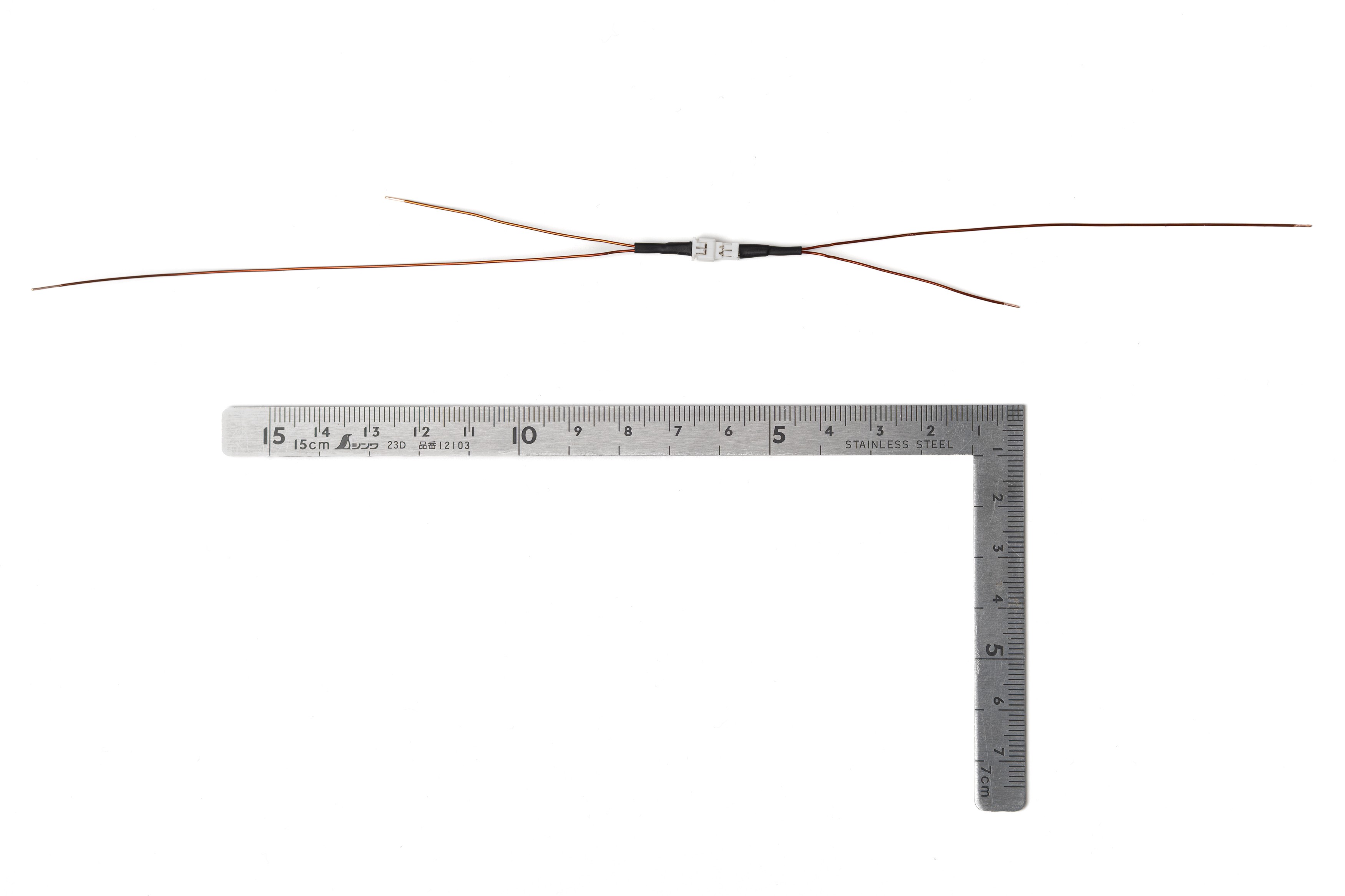
- Compact enough to pocket, 51×71×18mm body (excluding camera and screen bump)
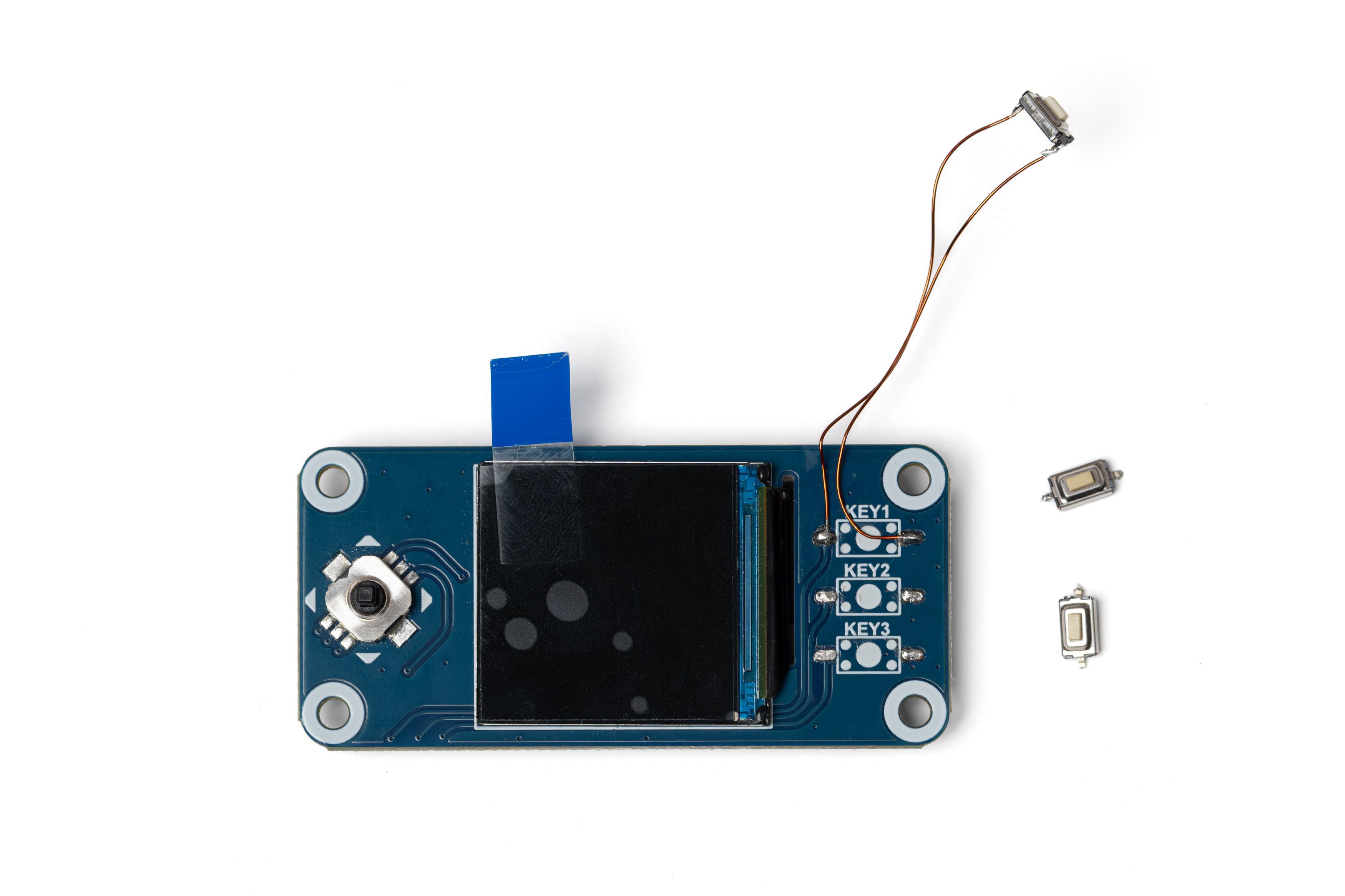
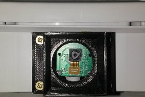
- Autofocus camera module with 2592×2592px JPEG capture
- 240×240px 1.4" LCD with a consistent 15–20 fps live preview
- 8 built-in photo filters
- Custom hotspot interface for fast image transfer that works on mobile and desktop
- 22 second boot time, 70-80 minutes per charge on a standard 14500 Li-ion cell
- Hot swappable battery
- Screen dims automatically when idle to save power
- TPU protective sleeve and lanyard design also available to print
Everything you need is in the GitHub repo:
- Bill of Materials - parts list with cost estimates
- Build Guide (PDF) - full step by step assembly
- Print ready Bambu Studio files - sliced for transparent PETG and PETG-CF
- Individual STLs - if you prefer to slice yourself
- CAD file (.STEP) - for modifications and remixes
- Software + installer - camera app with installation guide and controls reference
In addition, I made the build guide and the BOM available on this hackaday project page for quick browsing.
 Audrey Robinel
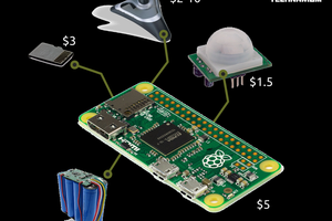
 Egle Marija Ramanauskaite
 PengxiangXu
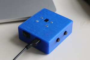
 Connor Yamada