 Doruk Kumkumoğlu
-
1Before You Start
Welcome to the Optocam Zero build guide!
Make sure you have all the required parts, tools and 3D printed components ready before you begin.
Read through all the steps before starting. Some steps have a specific order that can't be reversed easily.
This build requires basic soldering and desoldering. If you haven't soldered before, it's worth practicing on some scrap components first.
Take your time, especially with the ribbon cable (order extras to be safe) and the header pin soldering/desoldering. These are the most delicate parts of the build and mistakes here are difficult to undo. Be patient with it.
The 3D print files and software can be found at:
-
2Modify The LCD HAT
![]()
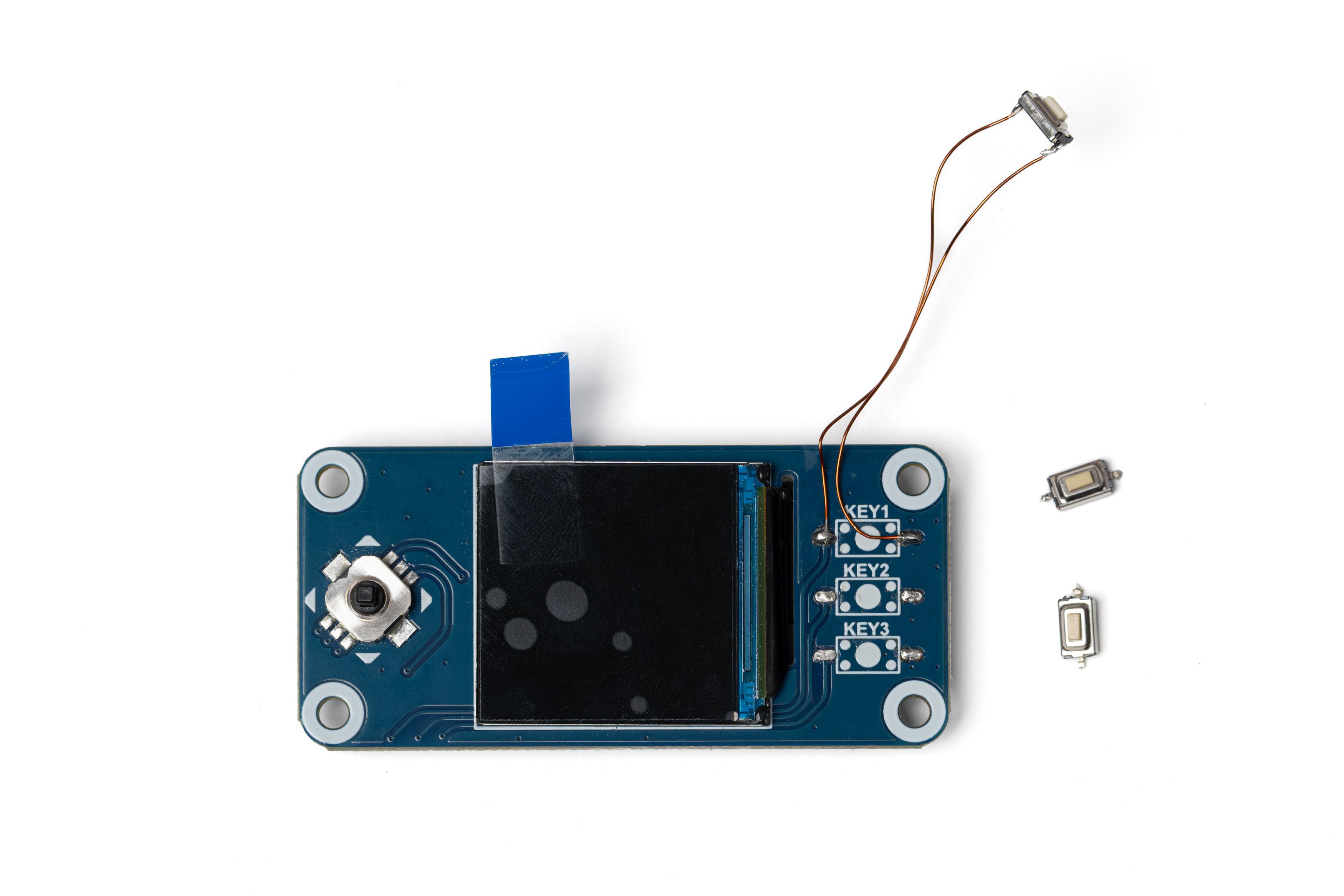
Desolder 3 buttons on the right side of the LCD HAT.
Cut two pieces of thin wire, around 4 cm each (I'm using 0.3mm enameled wire here). Bend the pins of one of the buttons inwards and carefully solder the wires to the pins.
Solder the other ends of the wires to the topmost key pads on the LCD HAT.
The soldered button will act as the shutter button. The remaining buttons will not be needed.
-
3Make The Power Cable
![]()
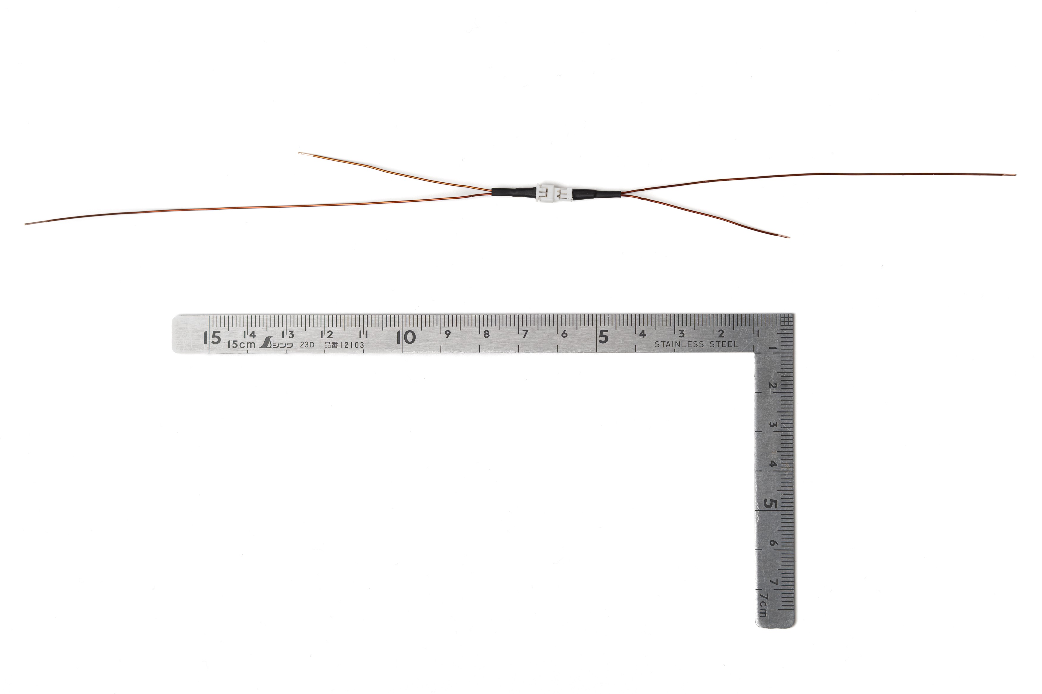
Prepare the power cable using 24 AWG cable and a Micro JST 1.25 Pitch 2 Pin connector as shown in the photo. Estimate the required length from the ruler in the photo.
This cable is for the connection between the battery HAT and the battery.
The connector allows for easy disassembly. If you'd rather skip the connector, just cut two 15–20 cm pieces of cable and use those for the connection.
-
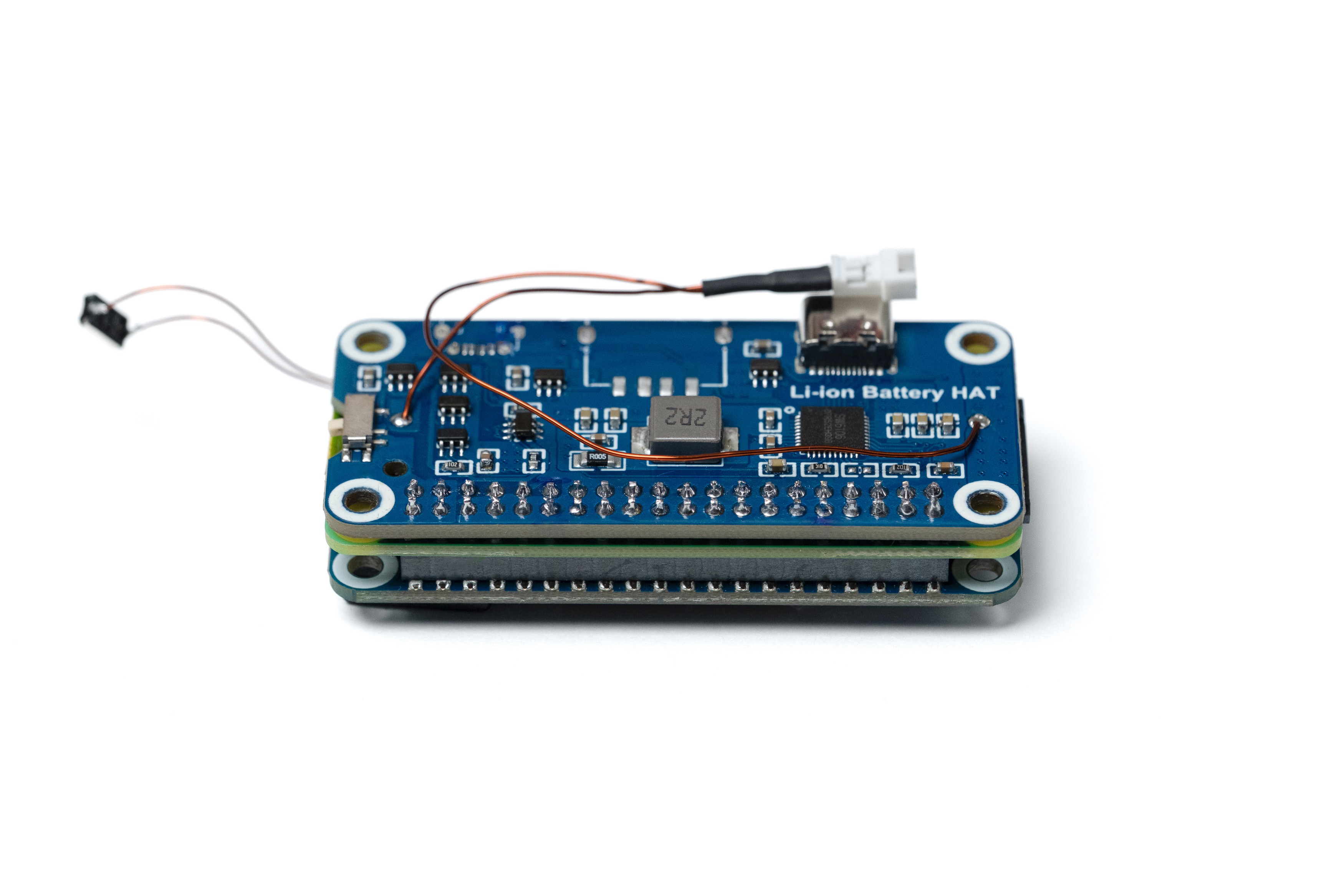
4Modify The Battery Hat
![]()
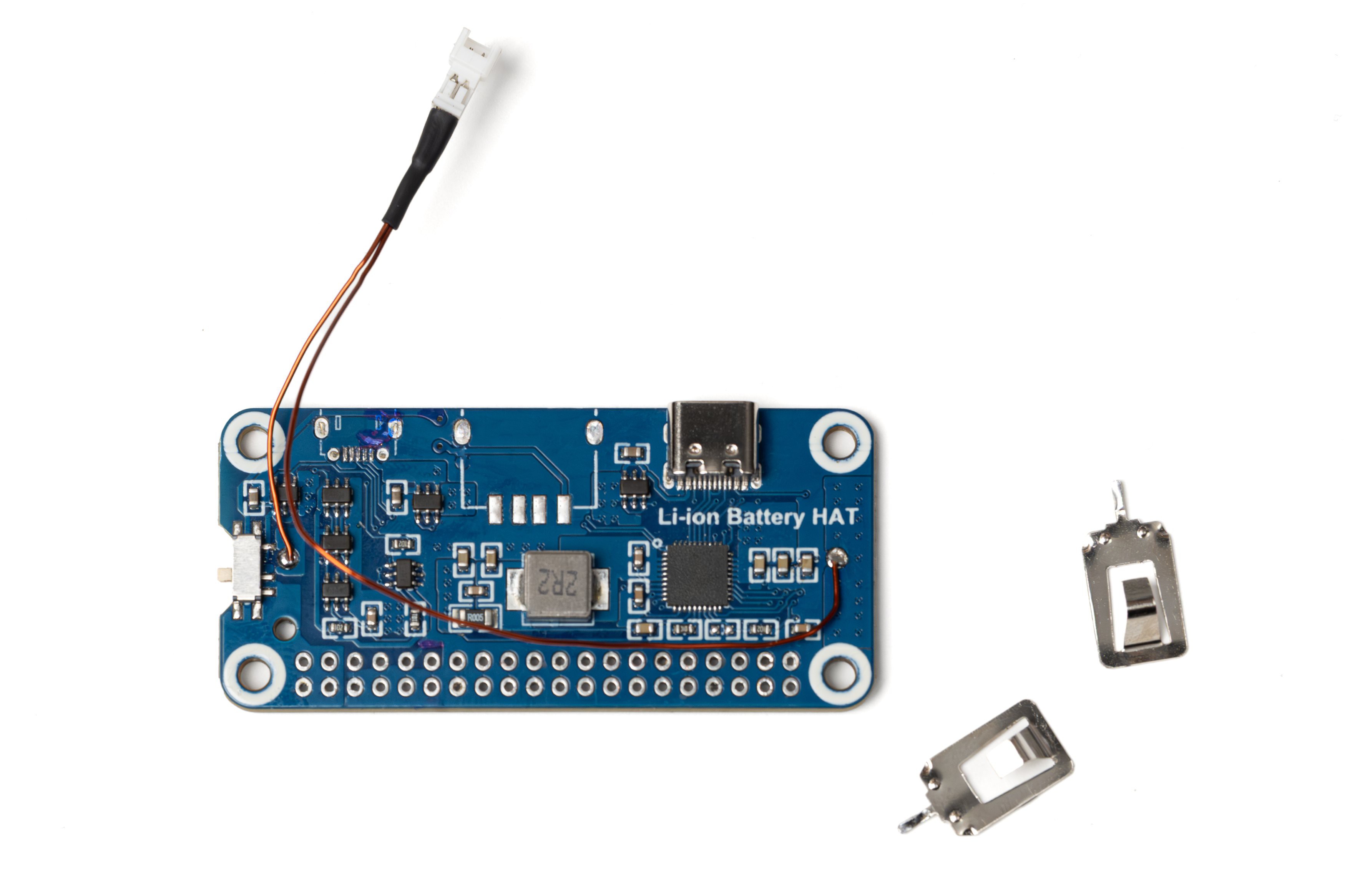
Desolder the battery holder, header pins, USB A and Micro USB connectors. To make removing the header pins easier, first cut the plastic part of the header between the pins using a side cutter. Make sure the header holes are completely clean of solder.
Remove the battery contacts from the battery holder. You can discard the holder, only the contacts will be needed.
Solder the male part of the power cable to the board as shown in the photo.
-
5Apply Kapton Tape to Pi
![]()
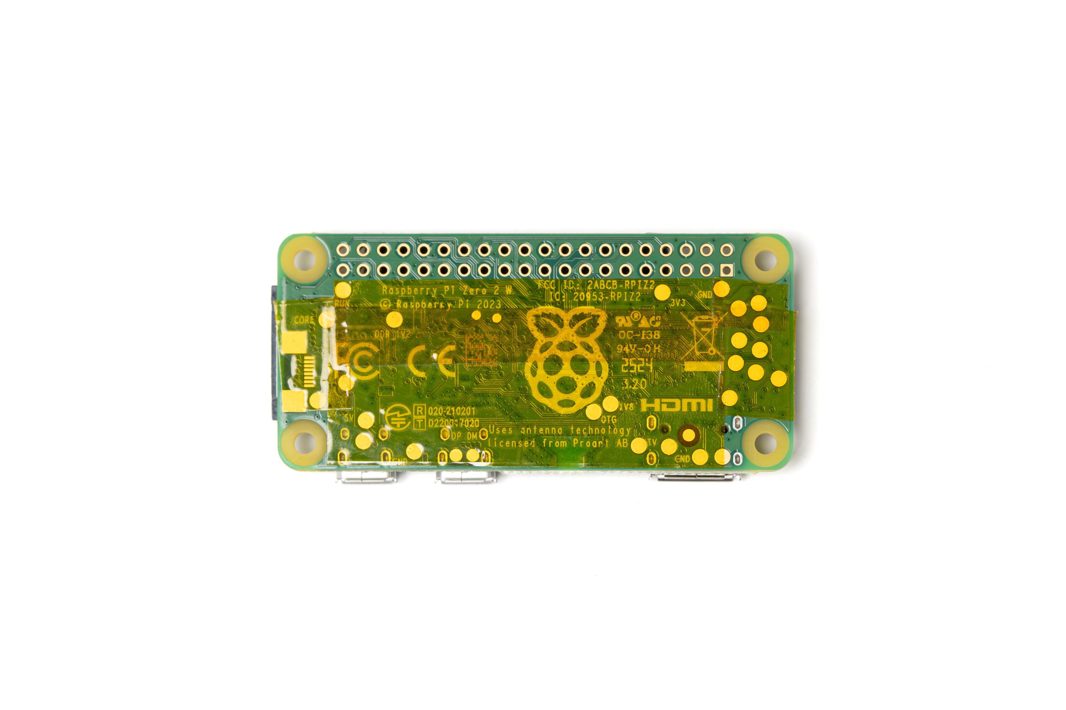
Apply Kapton tape to the underside of the Raspberry Pi Zero board. Make sure the header holes and the mounting holes are not covered.
This is to electrically isolate the board from the battery HAT when they're mounted close together.
-
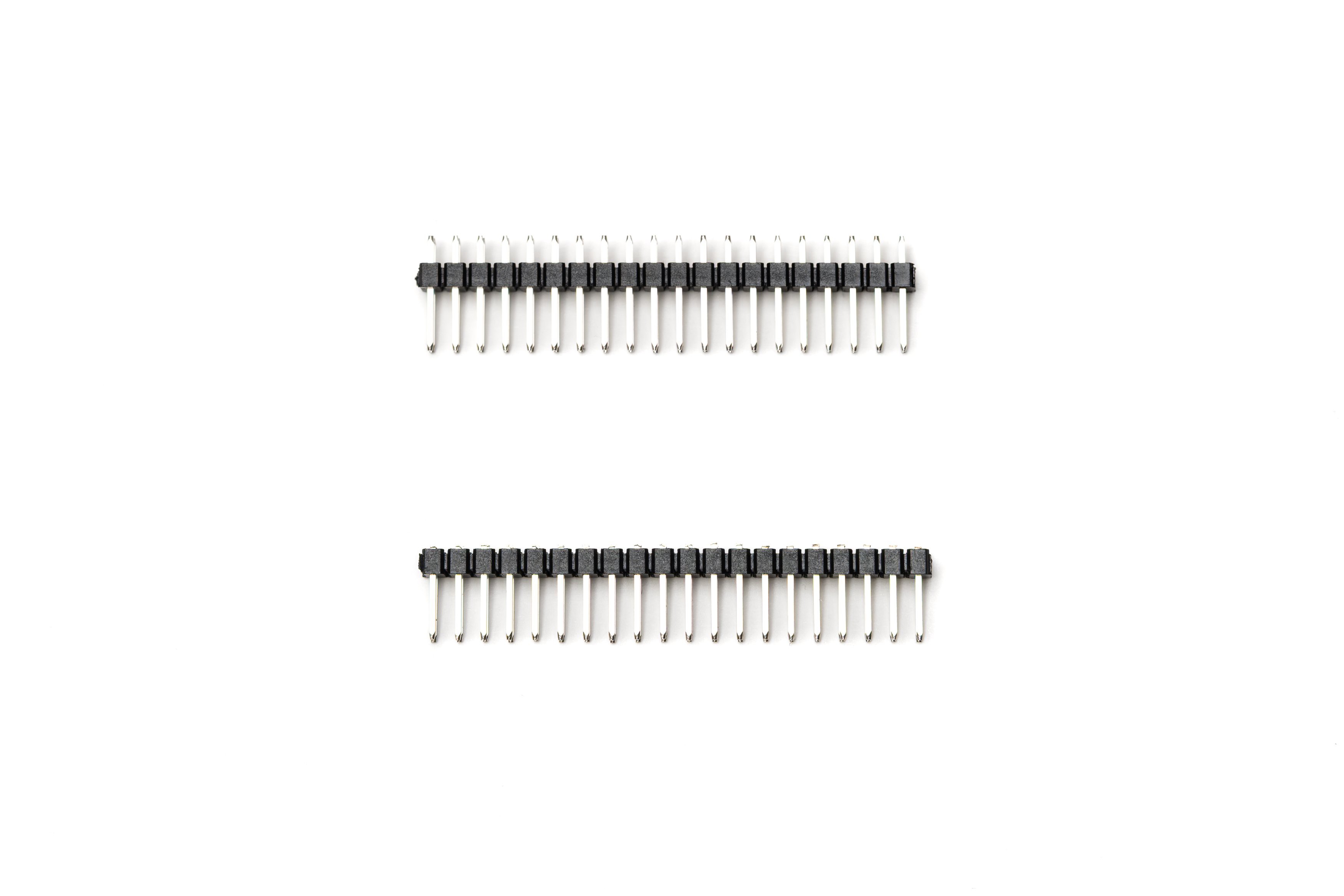
6Modify The Header Pins
![]()
With a side cutter, cut the short ends of the header pins flush to the plastic as shown in the photo (bottom one).
Then remove the cut pins one by one using pliers. 40 shortened pins are needed in total for the next step.
If you can find non-standard 8-9mm lenght pin headers, you can directly use the those without needing to shorten the pins.
-
7Mount the LCD HAT to Pi
![]()
Using 4 M3x16mm screws, 3D printed 4mm washers and M3 nuts (you may also use heat set inserts), connect the LCD HAT temporarily to the Raspberry Pi Zero as shown in the photo.
Make sure the screws are relatively tight and the two boards are as close to each other as the washers allow.
The M3 screws are not compatible with the mounting holes on the Pi normally. Either carefully enlarge the holes using a drill bit, or tap the holes using the screw.
-
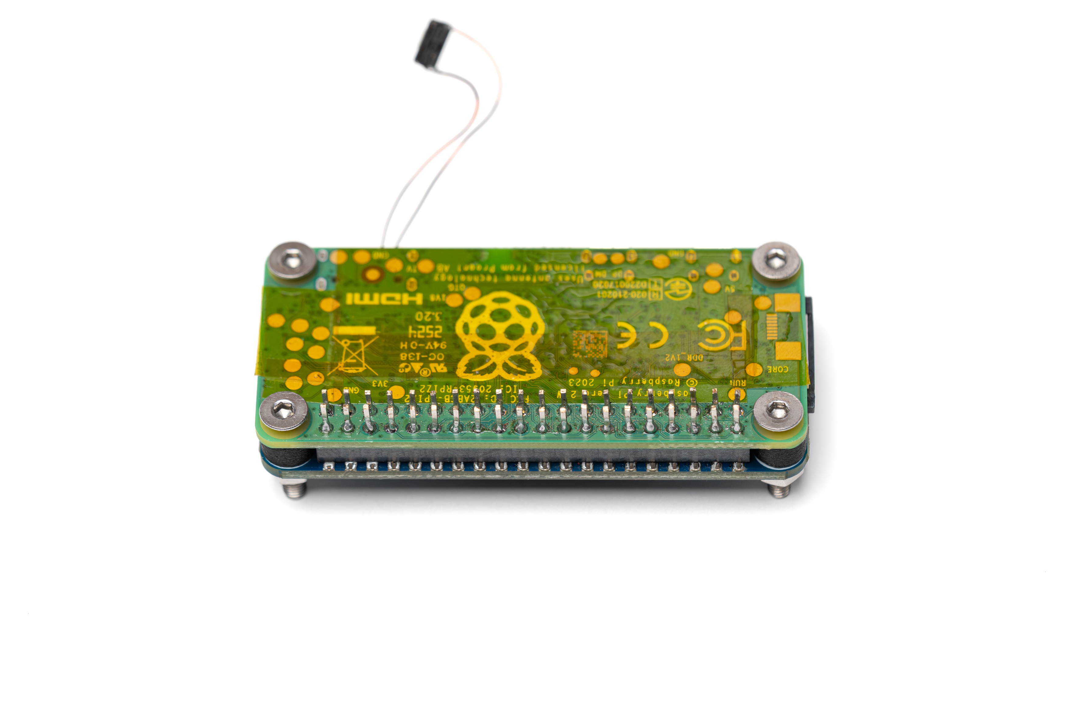
8Solder Header Pins to Pi
![]()
Push the previously shortened header pins into the solder holes one by one. Make sure they go through the Pi and seat on the LCD HAT connector.
Confirm they're pushed all the way and solder the pins one by one. Make sure to use a small amount of solder. The solder shouldn't extend up on the pins or form large blobs.
This custom header solution allows the boards to seat closer, resulting in a smaller camera body.
-
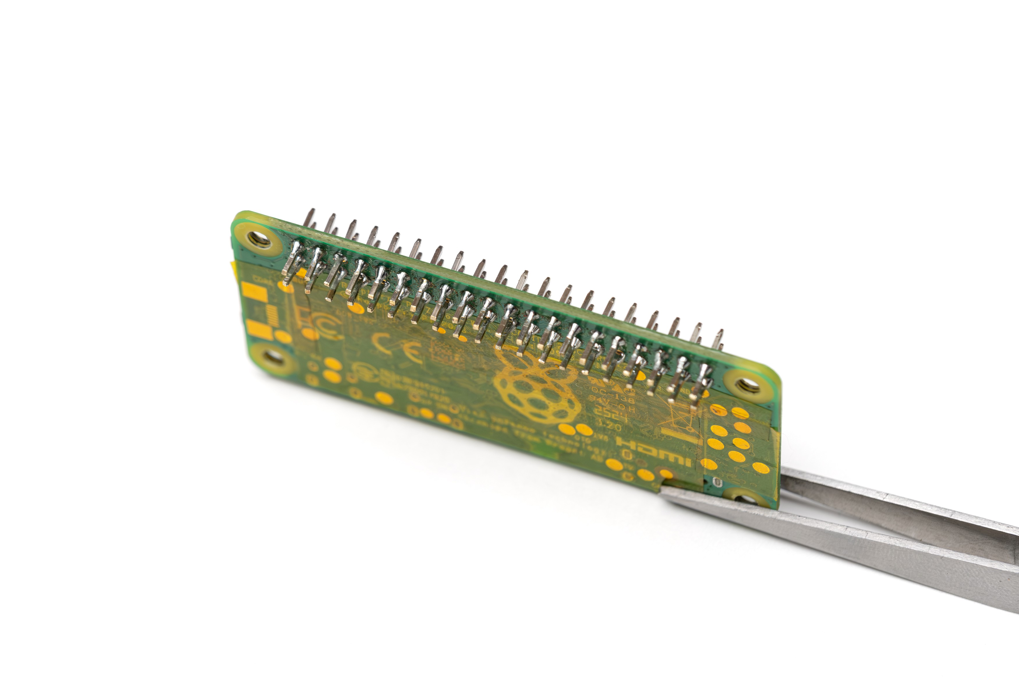
9Check The Pins
![]()
Remove the Pi and check the solder joints. Pins should be parallel and soldered well so they don't move.
Also at this stage, power on your Pi and check if it's working fine.
-
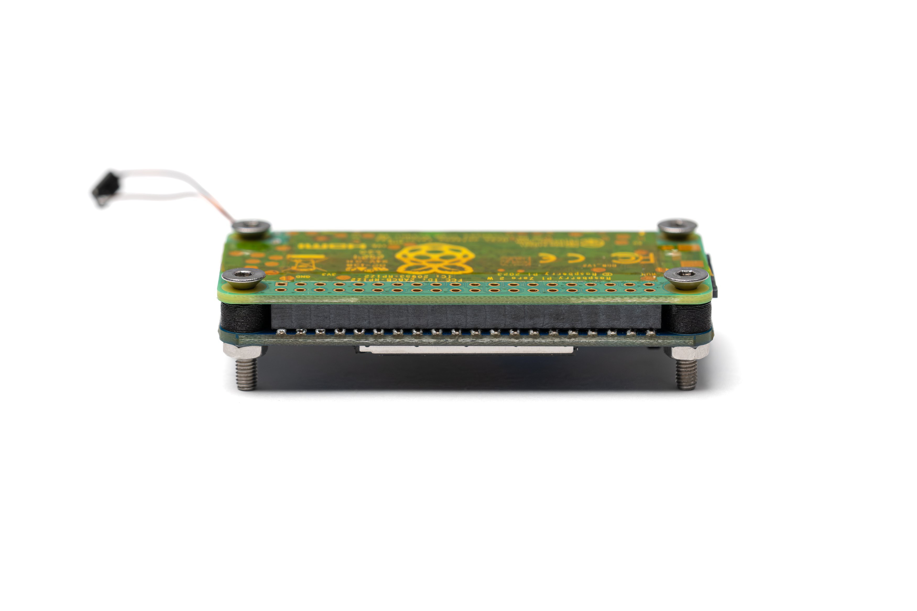
10Solder The Battery HAT to Pi
![]()
Mount The LCD HAT, Pi and the battery HAT to each other in the order shown in the photo. Pushing the pins into the battery HAT will be tricky, be patient with it. Secure this stack using 4 M3 screws, M3 nuts, 1mm washers and 4mm washers (this is not shown in the photo) similar to the previous step.
Confirm the boards are secure and they're as close to each other as the washers allow.
Solder all 40 pins to the battery HAT.
Remove the screws and washers. Remove the LCD HAT.
Optocam Zero
Optocam Zero is a Raspberry Pi Zero based compact digital camera made using off the shelf components.
Discussions
Become a Hackaday.io Member
Create an account to leave a comment. Already have an account? Log In.