 Mitsuru Yamada
1. Configuration of the controller system
Figure 1 shows the setup consisting of the Model Railway Controller MRC-2, the track layout, and the PERSEUS-9. The MRC-2 is located in the upper right corner of Fig. 1, and to its left is the homemade computer, the PERSEUS-9. Unless operating in automatic mode, the PERSEUS-9 is not required; the locomotive and turnouts can be controlled via the MRC-2’s control panel.
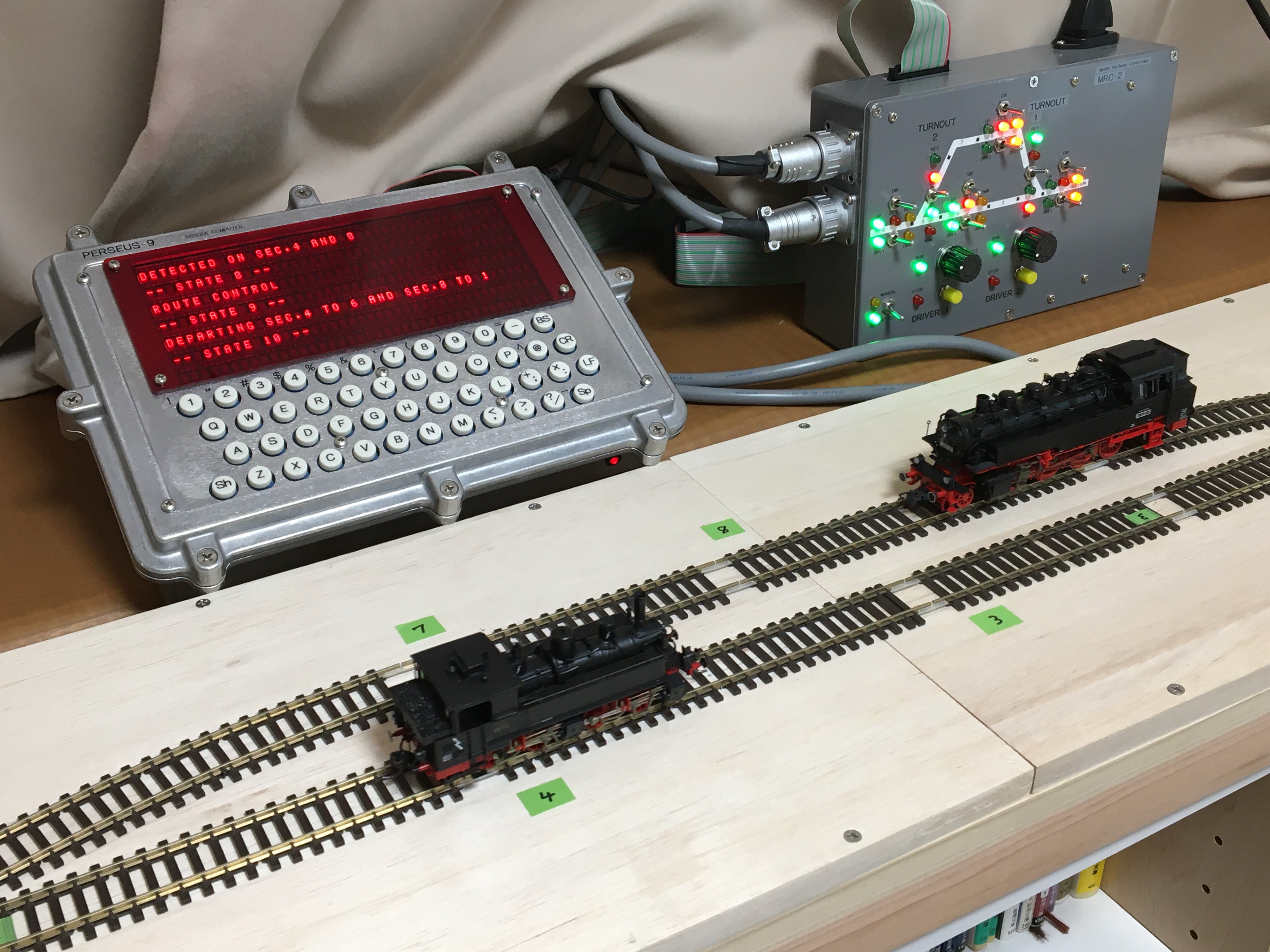
Fig. 1 Model Railway Controller MRC-2, layout track and PERSEUS-9 the computer.
This configuration is shown in Fig. 2. As shown in Fig. 2, the track layout to be controlled is assumed to be a very simple configuration that allows for train passing siding on a single track. There are eight sections, of which four—sections 1, 4, 6, and 8—are capable of block detection. Therefore, the MCR-2 is configured with a 4-channel block detection circuit.
The PWM drivers are independent 2-channel units, and each driver can be assigned to any section. In this way, two locomotives can run simultaneously on a single track, enabling passing maneuvers using a siding. The locomotives are controlled to move or stop based on logic control signals (1/0). Even when stopped, a PWM drive signal with a 3 % duty cycle is sent to the track; when a move command is issued, this duty cycle automatically increases to approximately 30 %. When a stop command is issued, the duty cycle automatically decreases back to 3 %, and the locomotive comes to a stop.
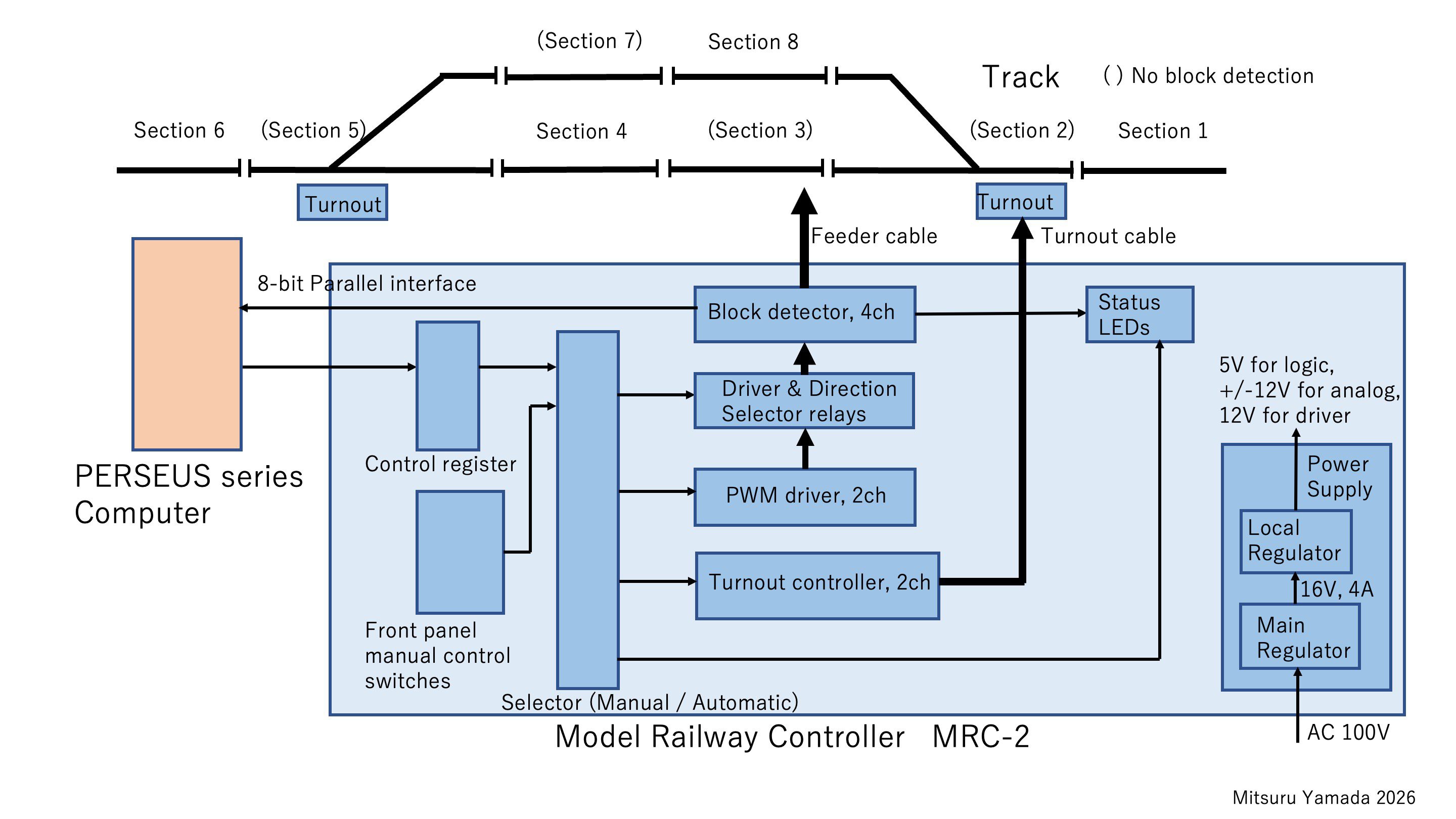
Fig. 2 MRC-2 configuration.
The PWM drive signal is then passing through a relay circuit to select the driver and the direction of travel. It is then supplied to the track via a transformer for block detection. The pulse current signal detected by the transformer is converted into a detection logic signal by an analog circuit. This signal lights up the red “DET” LED on the panel and is also made available for reading by an external computer.
In manual mode, toggle switches on the MRC-2 panel allow the user to select drivers 1 and 2 and set the direction of travel for any section. The current status is indicated by green and orange LEDs. When the driver pushbutton is not pressed, the locomotive is at a standstill; it moves only while the pushbutton is pressed. Turnout switching is also controlled by toggle switches, and the status is indicated by LEDs.
In automatic mode, the data selector routes all control logic signals from the parallel interface registers rather than from the panel switches. Each LED displays its status in the same way as in manual mode. Figure 3 shows the exterior of the MRC-2.
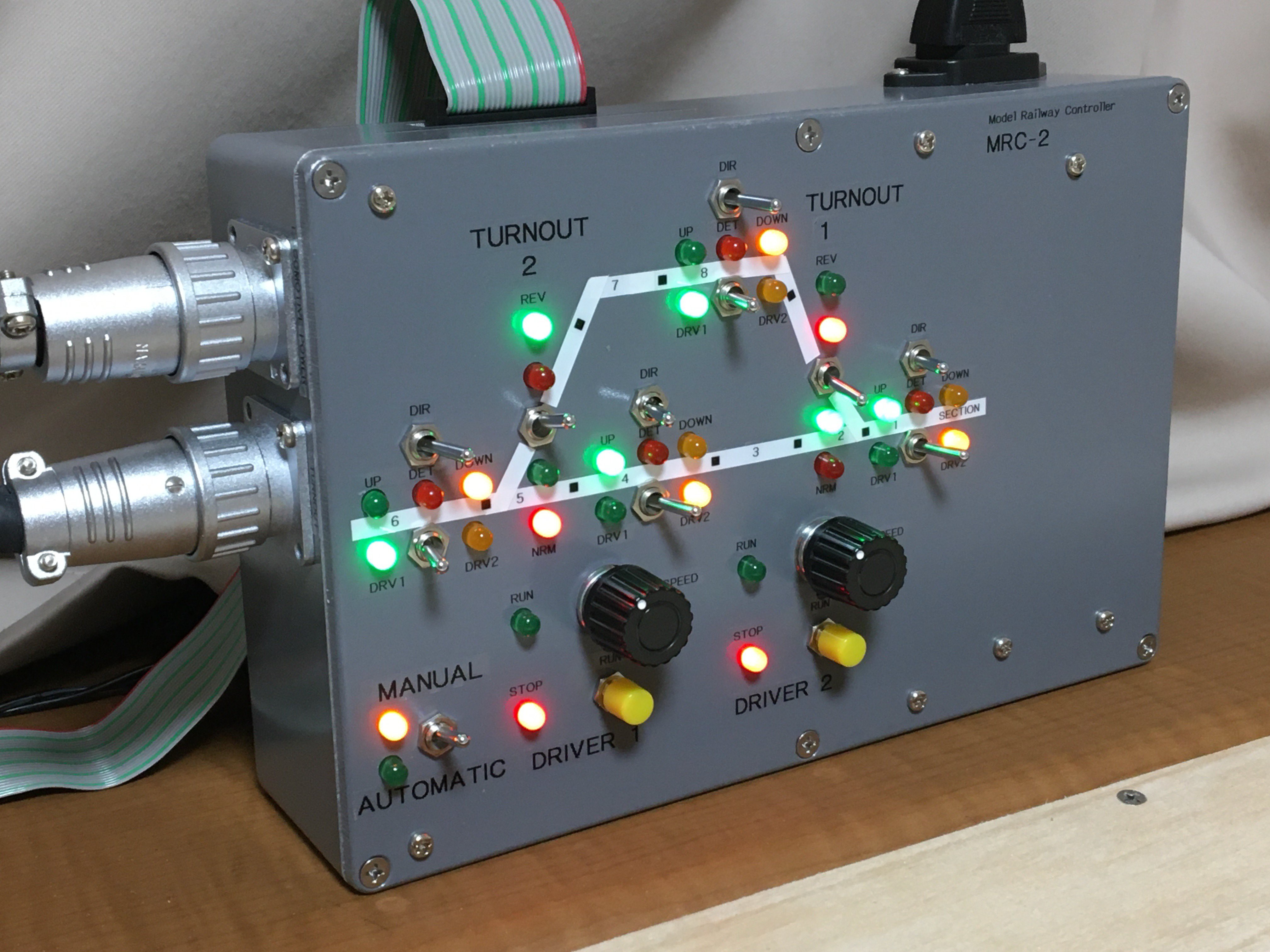
Fig. 3 Exterior of MRC-2.
2. MRC-2 circuit board
Figure 4 shows the MRC-2 circuit board. The rightmost section of the board contains the analog PWM driver circuits for the two channels. In the center of the board are 10 relays: 2 are used for acceleration and deceleration control of the PWM drivers, 4 are used to select the driver for each section, and 4 are used to select the direction of travel for each section. The leftmost section of the board contains the block detection circuits for the four channels. The toroidal transformer is used to detect pulse currents for block detection.
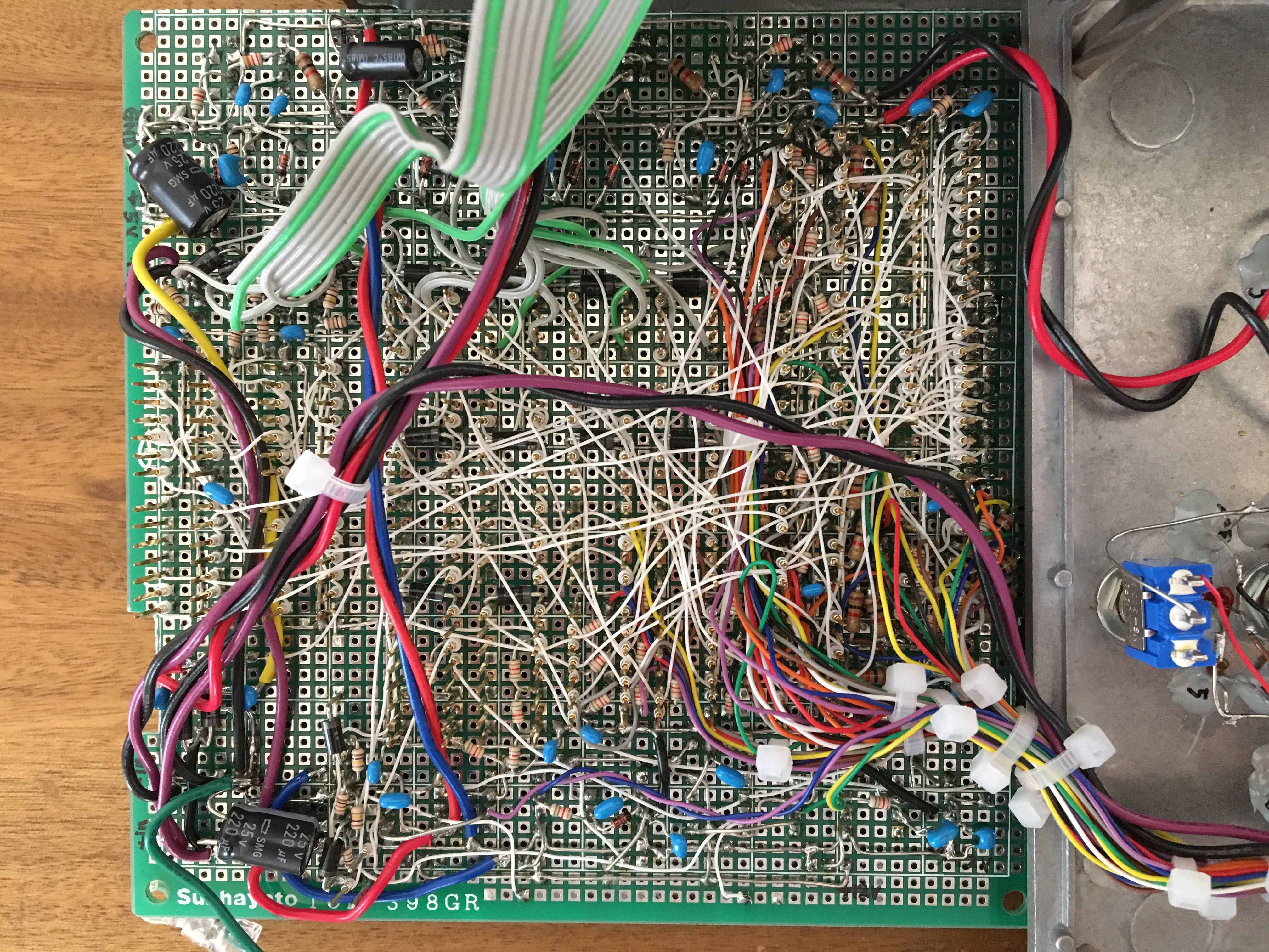
The bottom edge of the board contains a standard logic IC circuit for the 8-bit parallel interface connector, configuration registers, and data selector. The top edge of the board houses the turnout drive control circuit. The right side of the top edge of the board contains the local regulator circuit, while the right side outside the board houses the 16 V, 4 A main switching regulator. All of these circuits are housed in a HAMMOND 1550G die-cast aluminum case (222 mm x 146 mm x 55 mm). The full circuit diagram is in the attached file. The component layout figure and the wiring side of the circuit board photo are also in the attached file. In the following chapters, I will explain the...
Read more »
 Sayan
Sayan
 Hulk
Hulk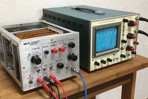

 Russell Kramer
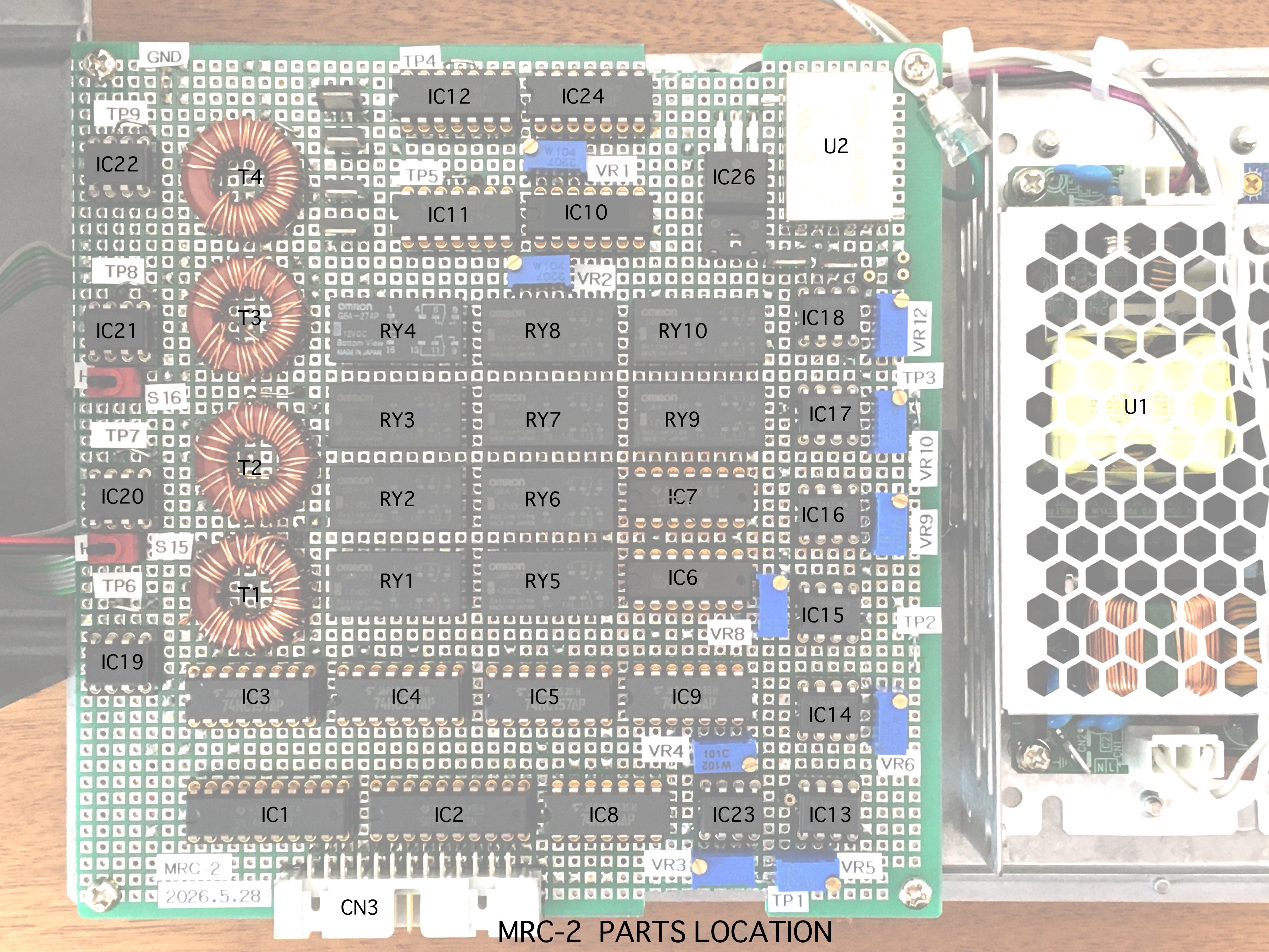