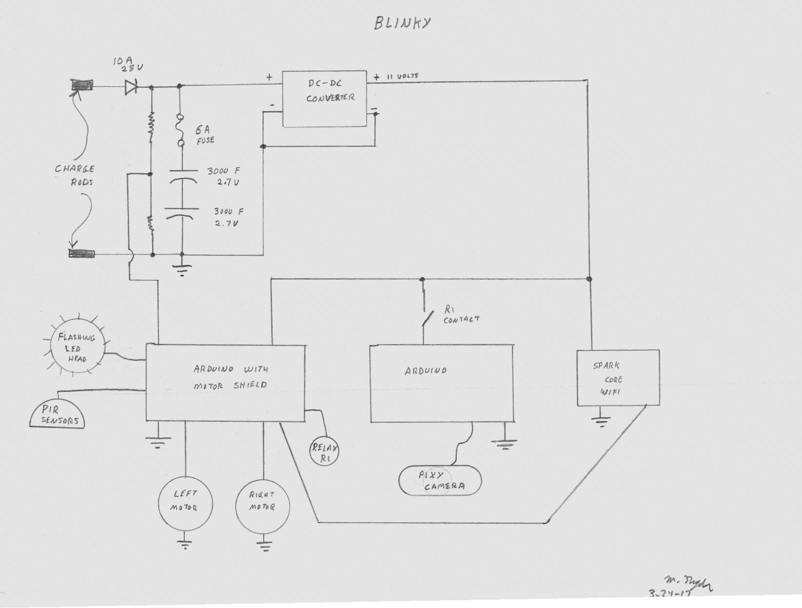
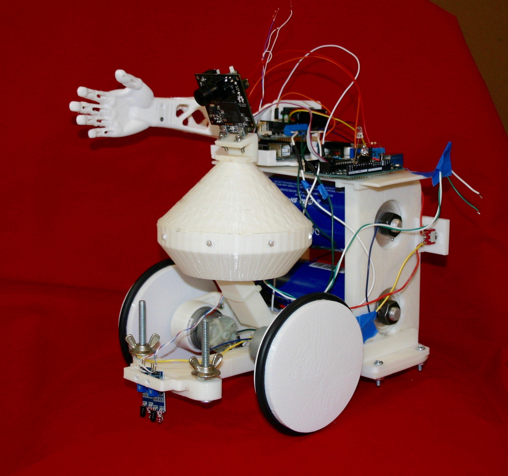
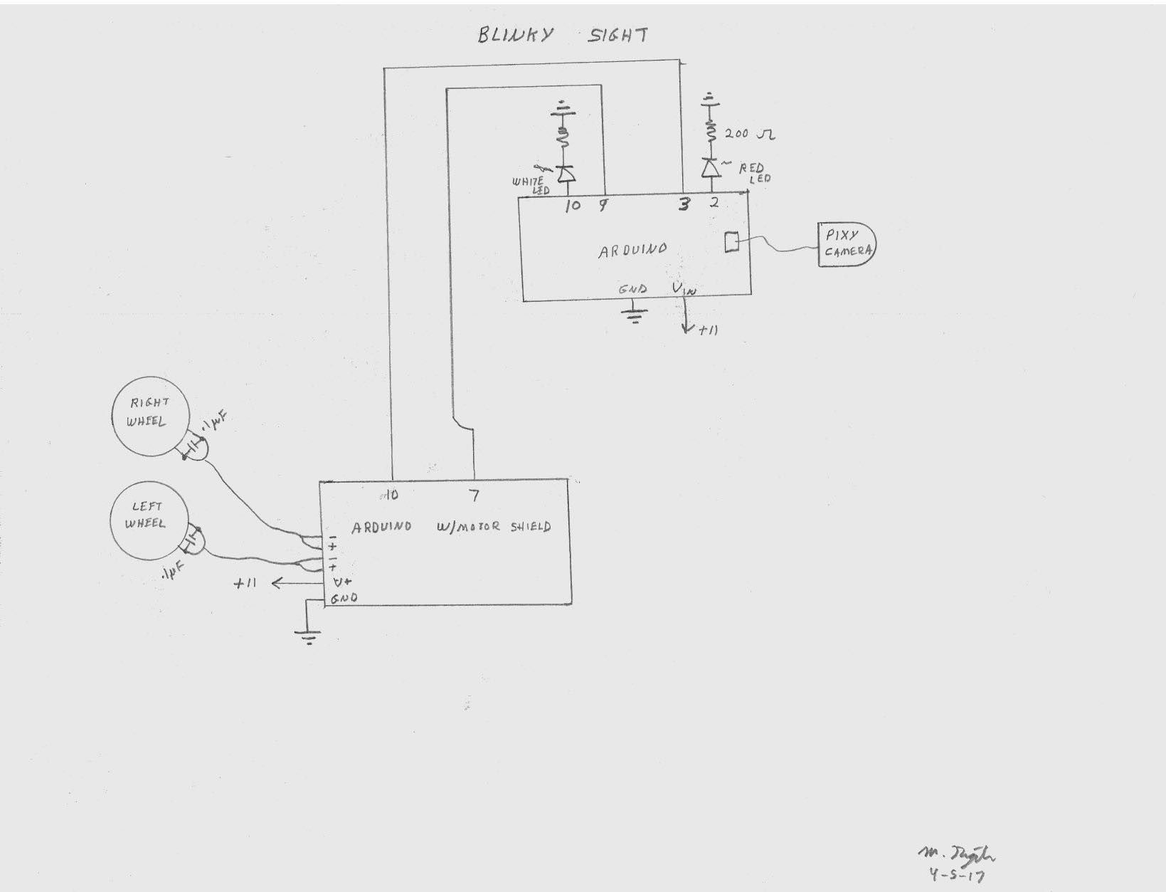
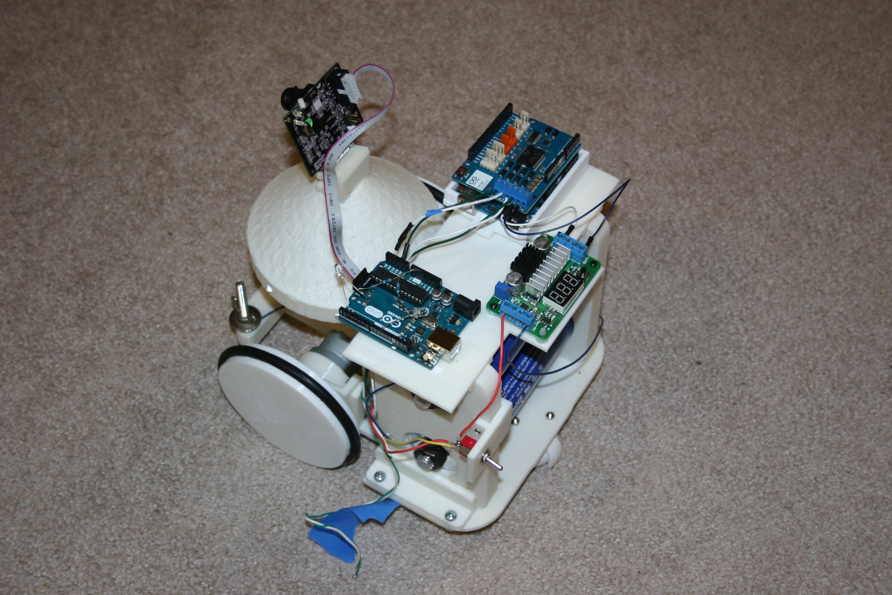
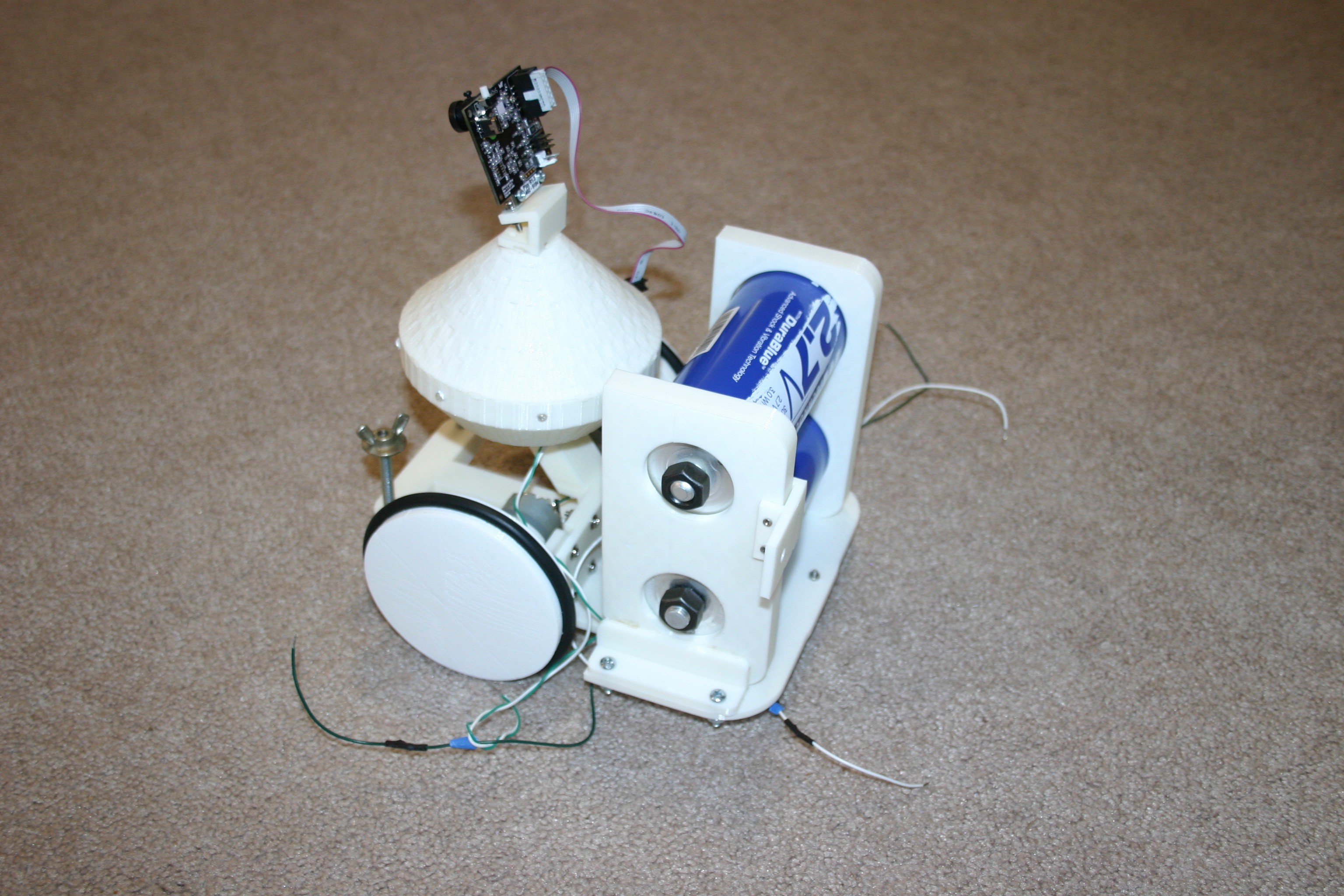
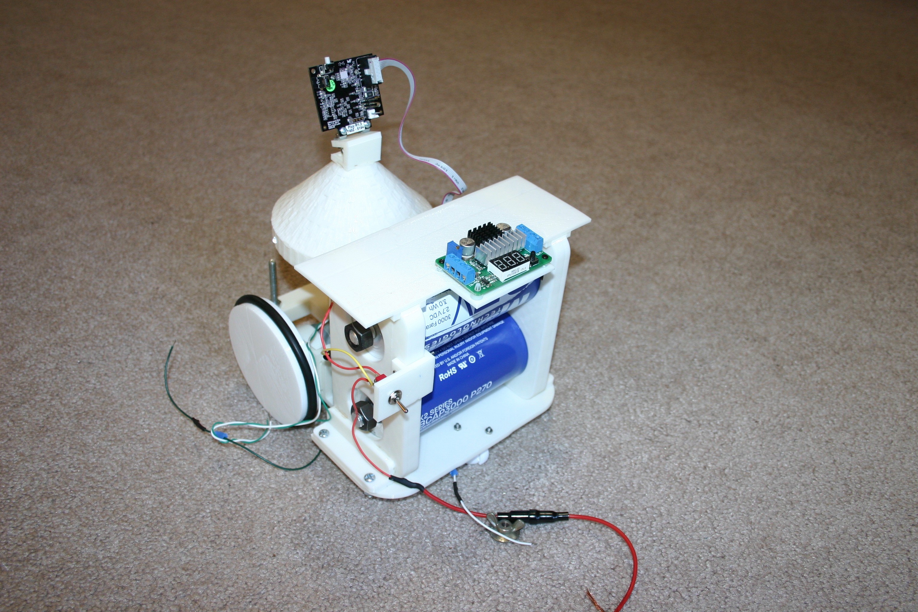
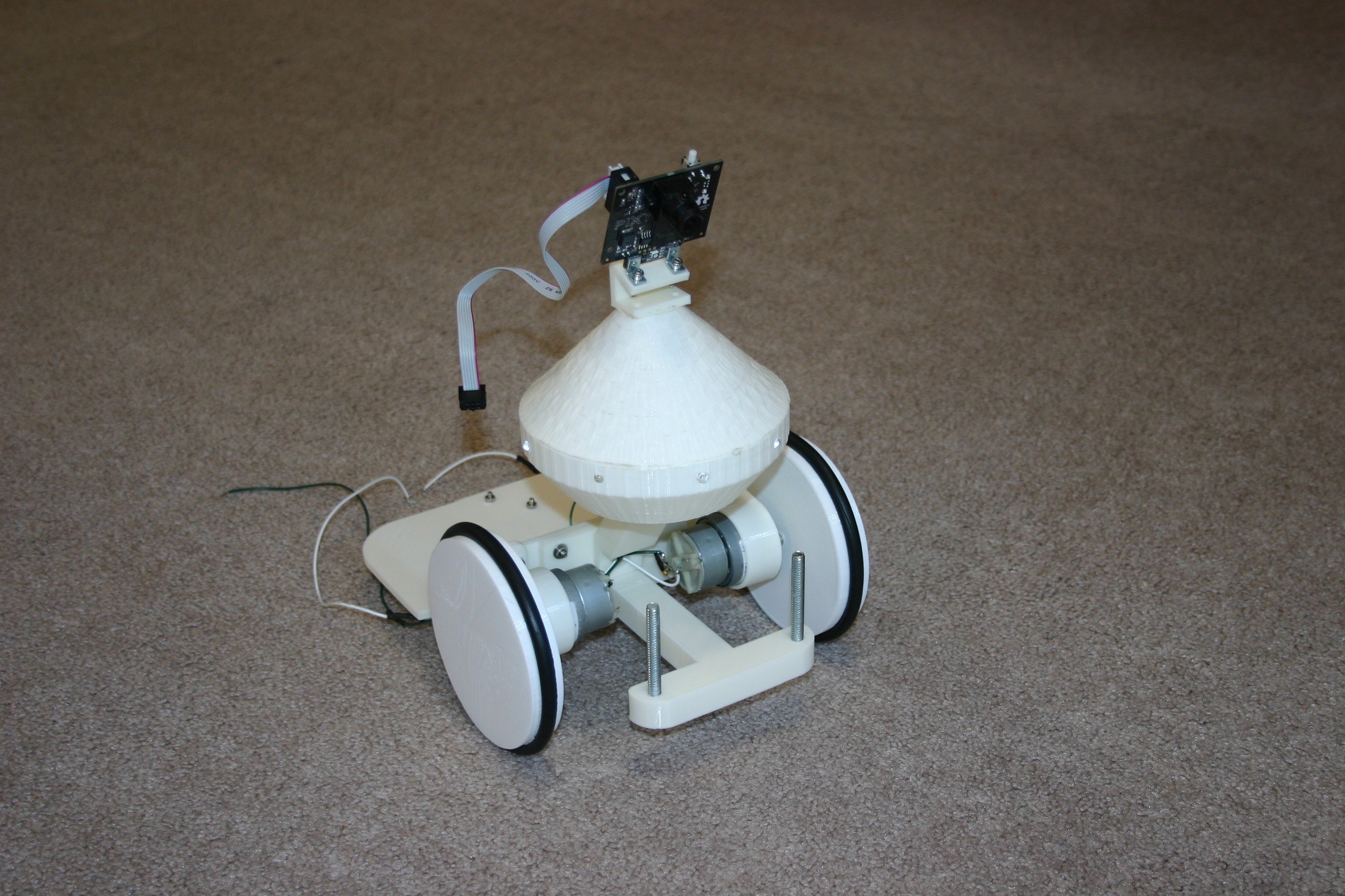
Below is an overall concept schematic of the electronics involved in Blinky. Blinky will wander about (changing course and retreating from obstacles) and frequently stop. While stopped, it will check the PIR sensors for movement and forward movement information to the Spark Core--from which it may be remotely retrieved. When the capacitor voltage reaches about 3.5 volts, Blinky will search for the charge station for a refuel. The charge station schematic and overview will be provided later.
Below is a video of Blinky moving toward a "target color" that will eventually be the charging station.
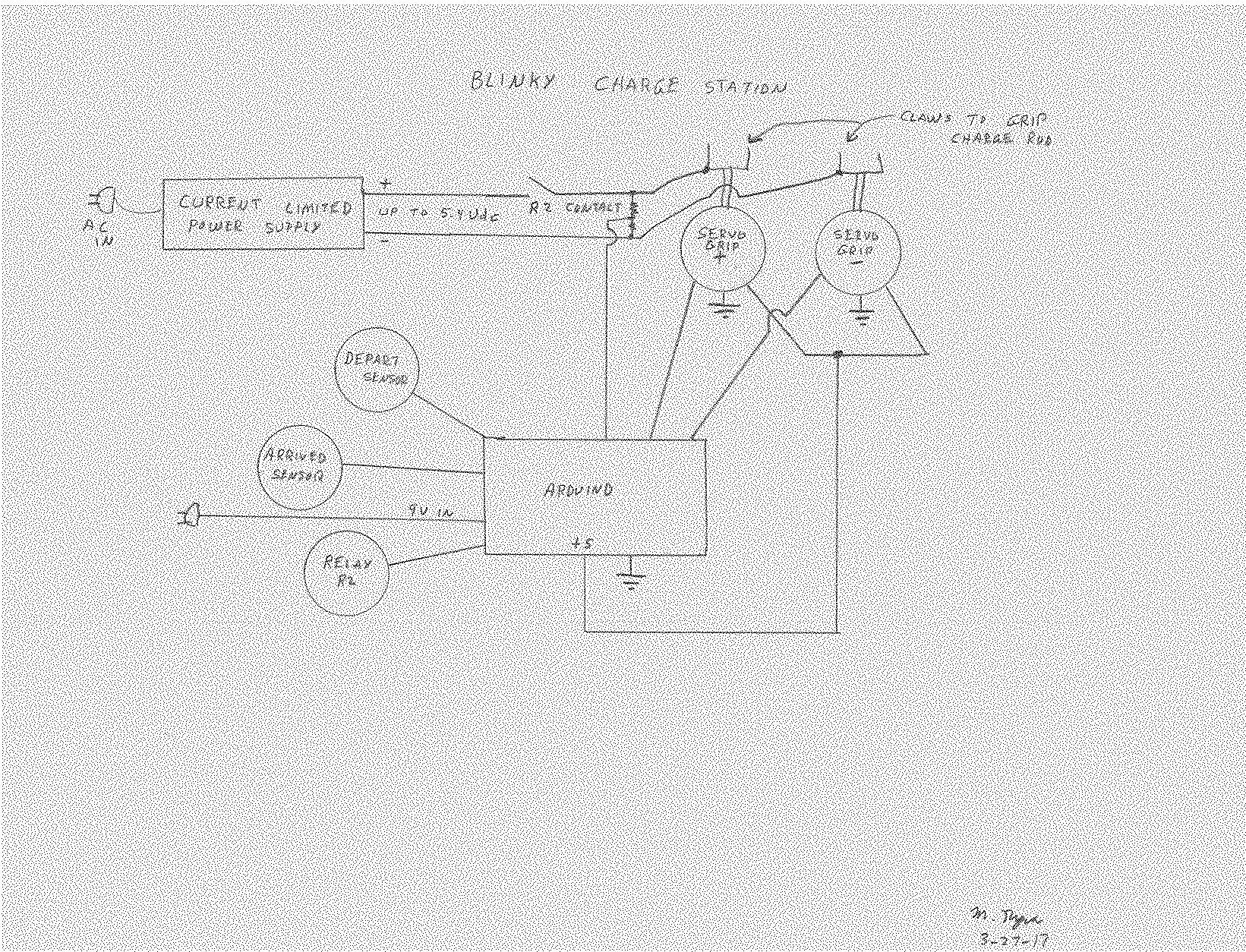
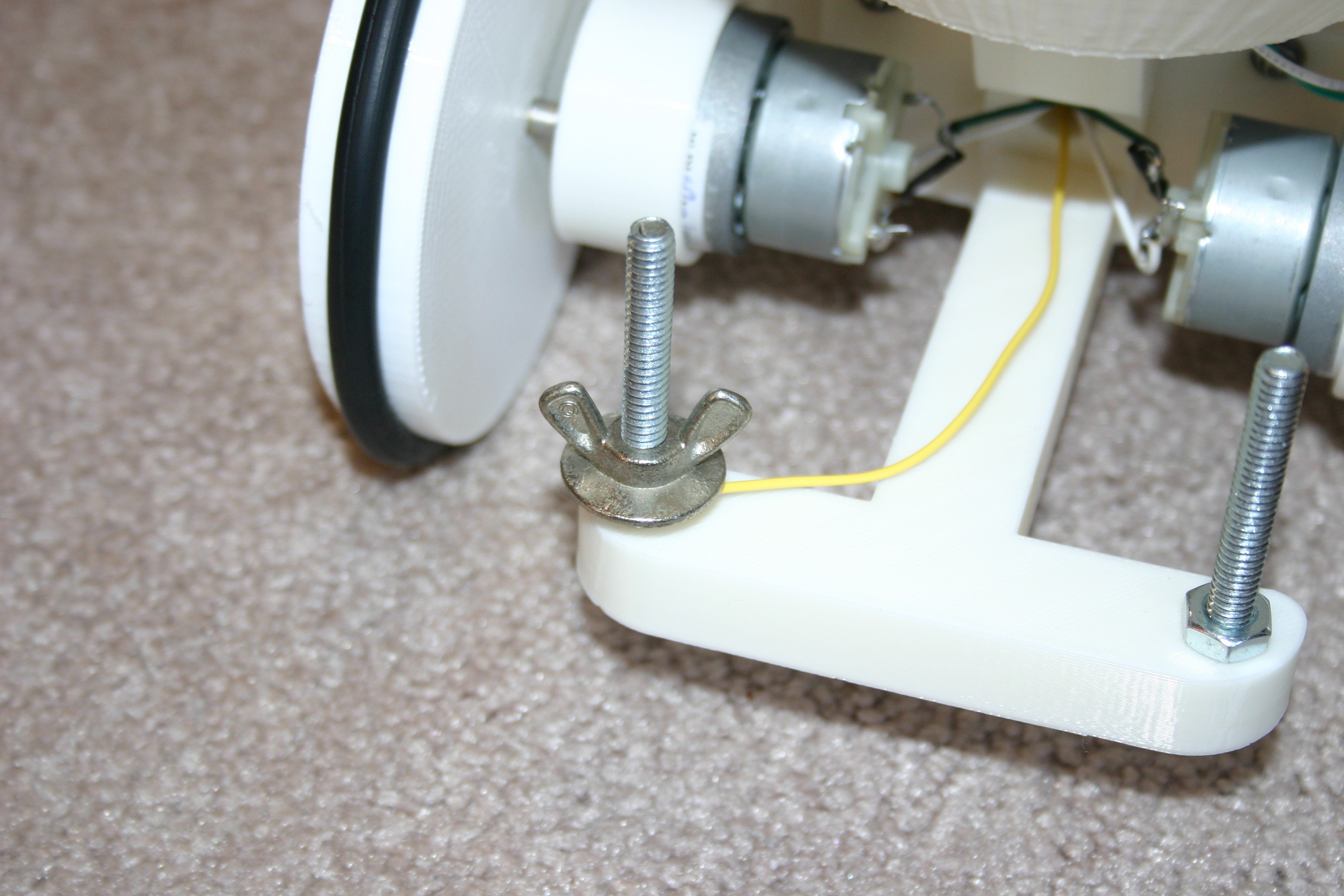
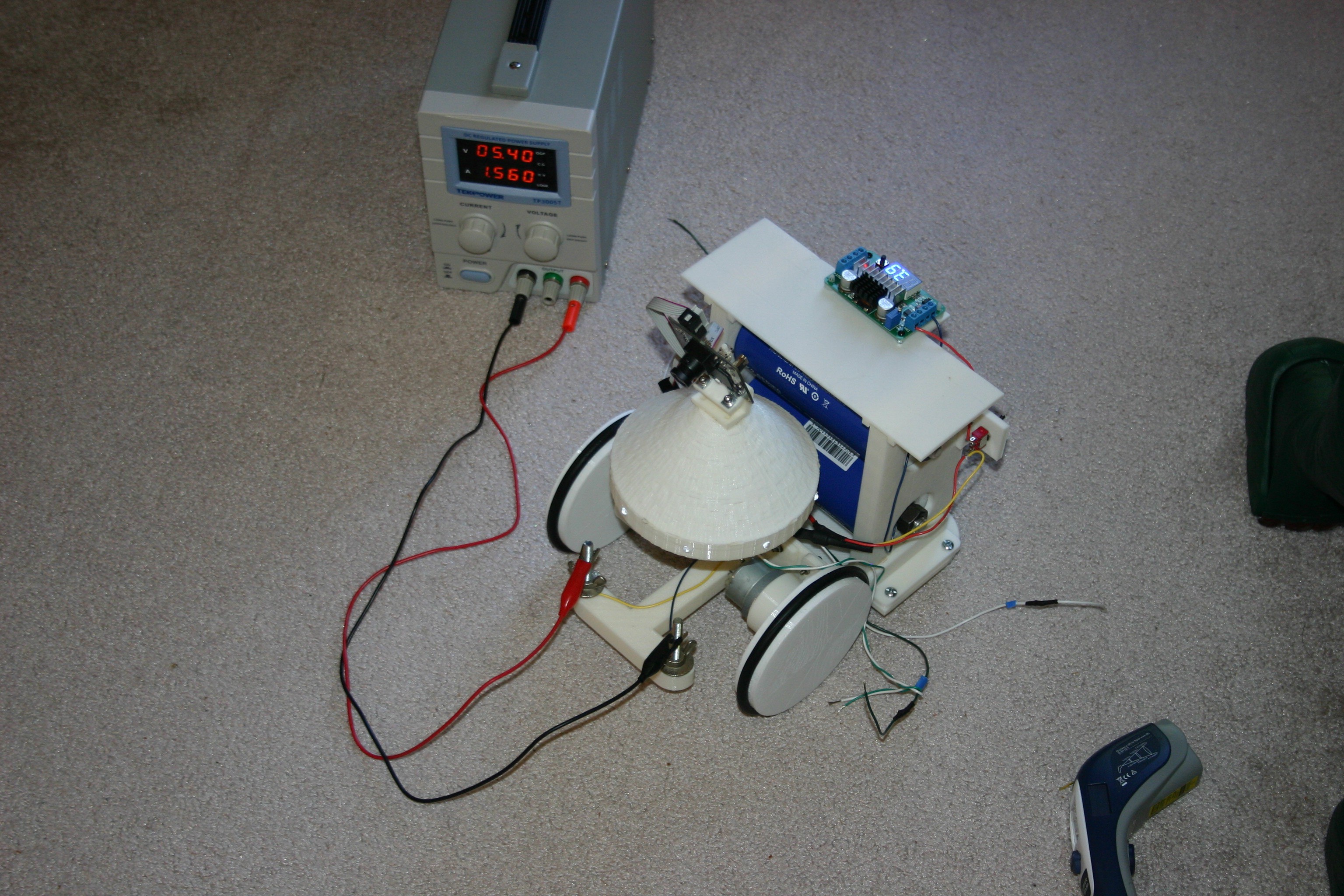
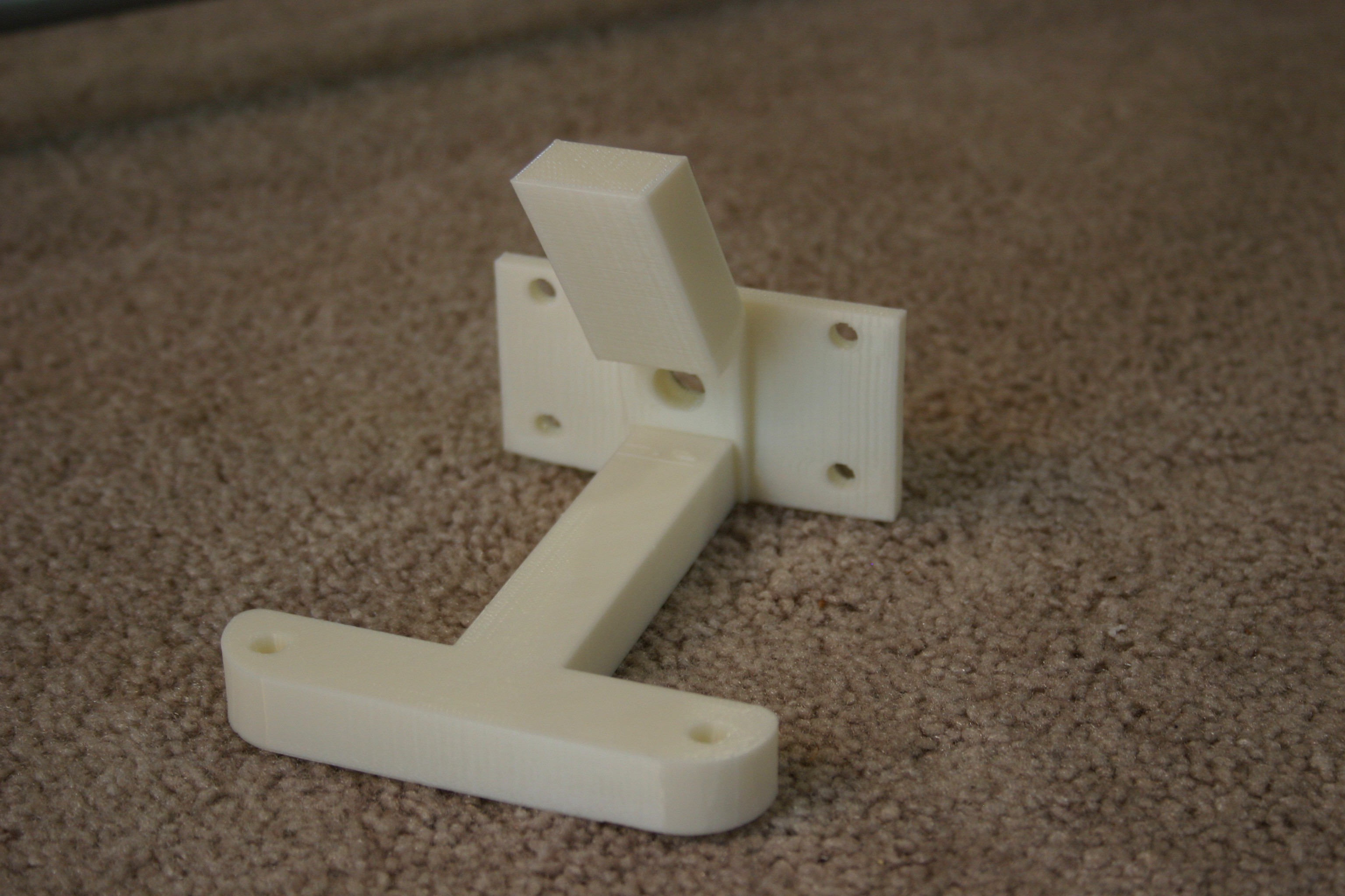
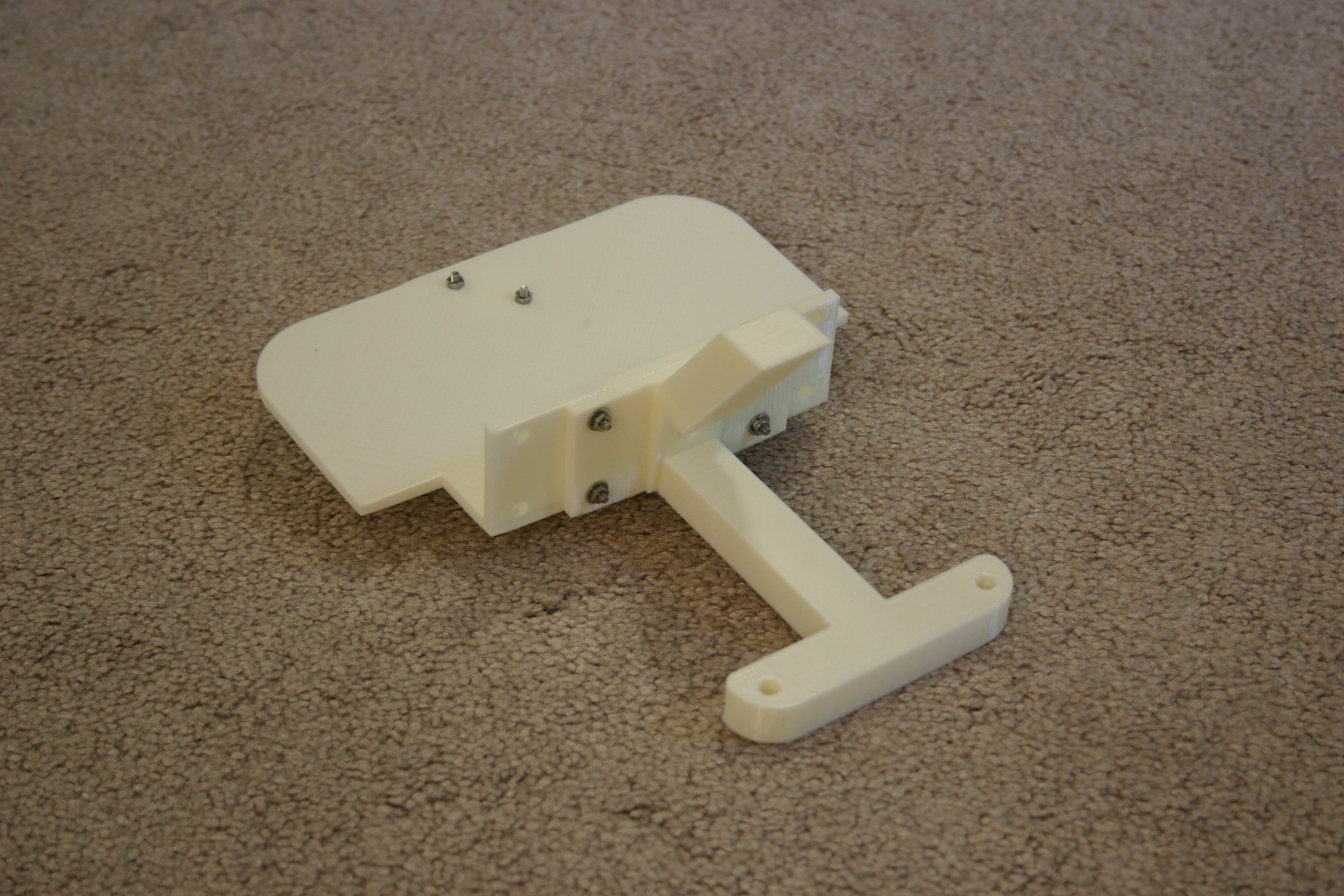
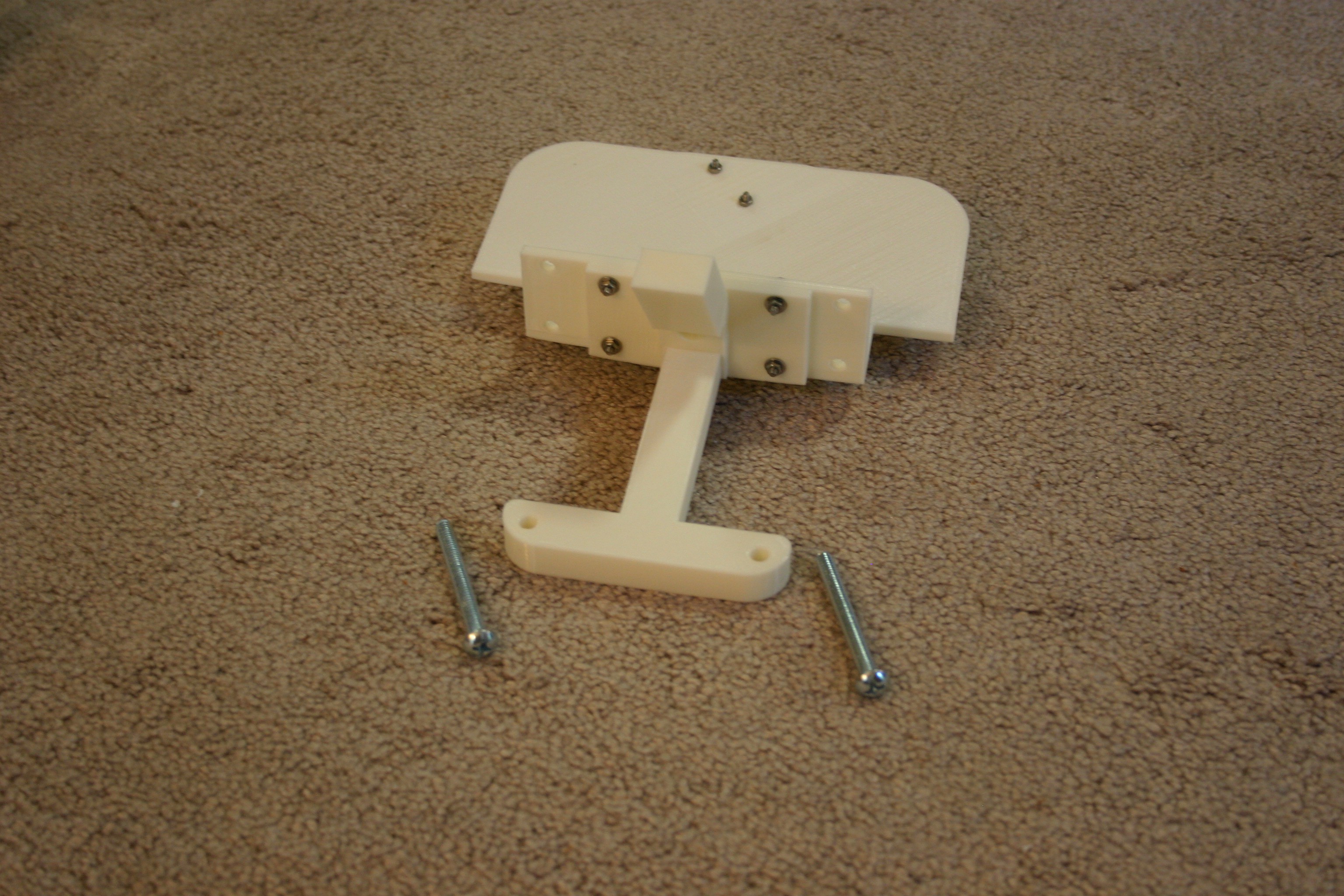
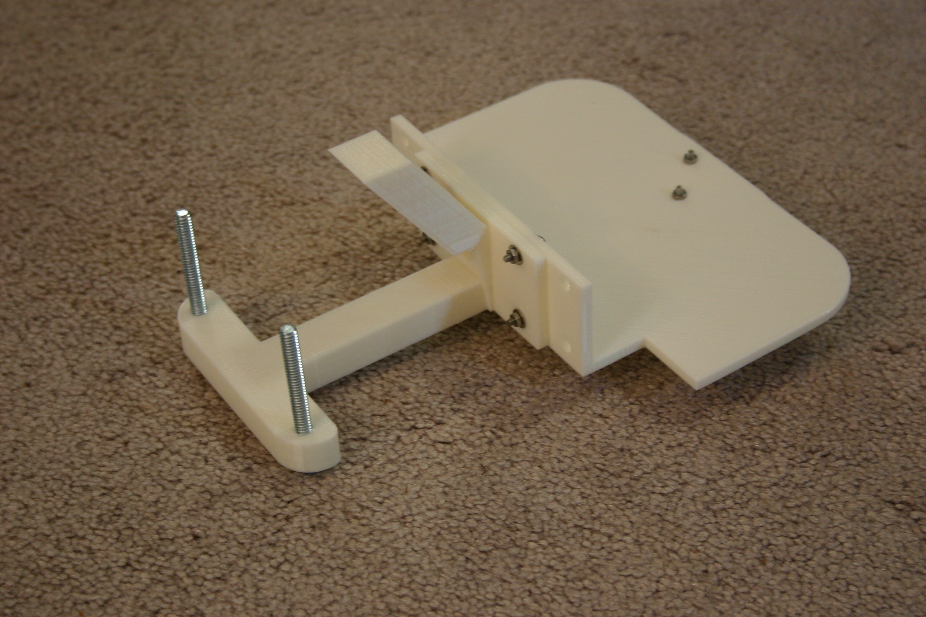
Below is the overview schematic of the charging (home) station. When Blinky arrives for refueling, the "arrived sensor" (probably a micro switch) will cause the servo controlled "claws" to grip the "charge rods" on Blinky. The "claws" will be lined with a conductor. The R2 contact will close and the current limited power supply will build the voltage up to 5.4 volts, at which point the claws will open and the "depart sensor" (probably a light) will let Blinky know that it is time to back out and roam again.
 Mike Rigsby




Great robot, really inspiring power system treating energy as food.
I'd suggest a small pair of EPM tractors in the charging station to make the power contacts with. You could fine-tune the position to hook up using a Hall sensor, and you only need to get close. Magnets make great electrical connections because of their nature, I use them as battery terminals regularly.
Using controllable magnets though, means once charged, the station can then release Blinky's charge port so it can disengage. Its just a pulse from a capacitor to switch the magnet on and off inductively and isnt part of the charge circuit.
https://en.wikipedia.org/wiki/Electropermanent_magnet