Close
0%
0%

R909-Tester: A Modular RP2040 zero Instrument

R909-Tester is a low-cost workshop instrument platform based on the Raspberry Pi RP2040 zero

Public Chat
Similar projects worth following
Overview
R909-Tester is a low-cost workshop instrument platform based on the Raspberry Pi RP2040 zero.
The project started as a simple continuity tester for identifying components and checking wiring during homebrew radio construction. As development progressed, additional functions were added, including a capacitance meter and a frequency counter.
Rather than building a dedicated instrument for each measurement task, the goal is to create a modular platform where new measurement functions can be added through software and minimal hardware changes.
Current Functions
• Continuity tester (Vopen:0.3V, Vshort:0.03mA)
• Capacitor meter (1000 pF to several µF range)
• Frequency counter (Up to 50MHz)
• Diodes identification
• Platform : OLED user interface, Rotary encoder operation
Overview

R909-Tester is a low-cost workshop instrument platform based on the Raspberry Pi RP2040 zero.

The project started as a simple continuity tester for identifying components and checking wiring during homebrew radio construction. As development progressed, additional functions were added, including a capacitance meter and a frequency counter.

Rather than building a dedicated instrument for each measurement task, the goal is to create a modular platform where new measurement functions can be added through software and minimal hardware changes.

Current Functions

  • Continuity tester (Vopen:0.3V, Vshort:0.03mA)
  • Capacitor meter (1000 pF to several µF range)
  • Frequency counter (Up to 50MHz)
  • Diodes identification
  • Platform : OLED user interface, Rotary encoder operation

Hardware Concept

The hardware is intentionally simple:

The design philosophy is to keep the hardware accessible to hobbyists while implementing measurement functions primarily in software.

Software Architecture

As more functions were added, the original sequential program structure became difficult to maintain.

To solve this problem, the firmware is being migrated to a state-machine architecture.

Each measurement function is implemented as an independent module:

This approach allows new functions to be added without major modifications to existing code.

Why This Project Exists

Many hobbyists already own a digital multimeter.

The purpose of R909-Tester is different.

It is intended as an experimental platform where measurement techniques can be developed, tested, and shared. The project also serves as a learning vehicle for RP2040 programming, embedded software design, and measurement algorithms.

Future Plans

Development logs will be added as the project evolves.
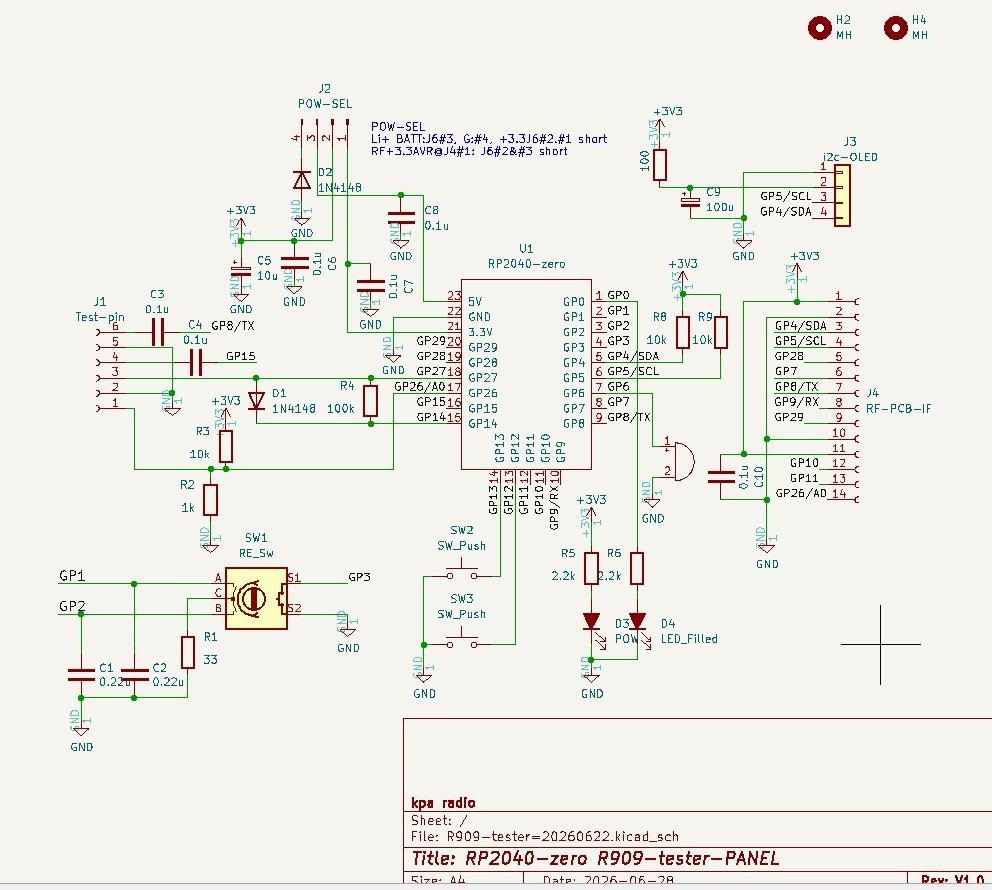
R909-tester._SCM.jpg

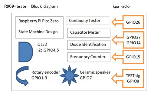
The circuit diagram of R909-tester

JPEG Image - 184.94 kB - 07/03/2026 at 10:12

Preview

  • 1 × Raspberry Pi Pico zero Waveshare RP2040 zero
  • 1 × OLED display
  • 1 × PCB Electronic Components / Misc. Electronic Components

  • R909-tester PCB is ready, but found a bug during assembly!

    nobchaa day ago 0 comments

    To speed up my experiments and add more features, I decided to design and build a custom PCB. However, during PCB layout, I accidentally flipped the orientation of the I2C pin header for the OLED display and routed it on the wrong side! Fortunately, it doesn't affect debugging at all—I just mounted the display turned around, and it works fine for now.

    https://nobcha23.hatenablog.com/entry/2026/07/20/191050

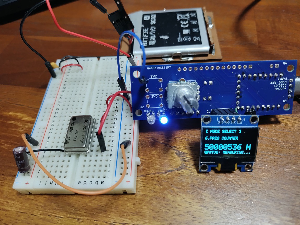
    The tester includes a continuity tester, capacitance meter, diode checker, and a frequency counter. Surprisingly, the frequency counter responds up to 50 MHz!
    ---50MHz displaying

    I've uploaded the Gerber files for this PCB to GitHub.
    --Link address Gerber sketch:
    https://github.com/Nobcha/R909-tester/blob/main/R909-tester_Rev1.0_ERRATA.zip

  • Firmware Architecture: Taming Complexity with a State Machine

    nobcha07/11/2026 at 08:19 0 comments

    This is a project log for R909-Tester: A Modular RP2040 zero Instrument

    In the previous log, I walked through the hardware design. Now that the prototype is taking shape on a breadboard, it's time to dive into the firmware—specifically, how I'm managing the growing complexity of this multi-function instrument.

    The Problem with Simple Sketches
    When this project started as just a continuity tester, the firmware was trivial. A single loop() function ran the test and that was that. But as I added a capacitance meter, a frequency counter, and a diode identifier, things got messy fast.

    The naive approach would be something like this:

    cpp
    void loop() {
      if(mode == 0) continuityTest();
      else if(mode == 1) capacitorMeter();
      else if(mode == 2) frequencyCounter();
      // ... and so on

    This works for a handful of functions, but it quickly becomes a maintenance nightmare. What happens when you want to add long-press vs. short-press button handling? What about sub-states within a measurement mode, like charging, waiting, and calculating for the capacitance test? 

    The answer, as many experienced embedded developers will tell you, is a state machine. I adopted this approach for the R909-Tester, and it's made all the difference.

    Two-Level State Management
    Level 1: Application Modes (Top-Level States)

    First, I defined the main operating modes of the instrument:

    cpp
    enum Mode {
      CONTINUITY,
      CAPACITOR,
      COUNTER,
      DIODE
    };
    

    Switching between these modes is triggered by the rotary encoder. The logic is clean and contained:

    cpp
    switch(currentMode) {
      case CONTINUITY: continuityTest(); break;
      case CAPACITOR:  capacitorMeter();  break;
      case COUNTER:    frequencyCounter(); break;
      case DIODE:      diodeChecker();    break;
    }


    Adding a new function is as simple as adding a new enum value and a case statement. This modularity is a huge win for code organization and maintainability. 

    Level 2: Internal States (Sub-States)
    But the story doesn't end there. Some measurement modes have their own internal sequences. The capacitance meter, for example, needs to:

    Discharge the capacitor

    Wait for the discharge to complete

    Start charging through a known resistor

    Wait for the voltage to reach 63.2% of VCC

    Calculate capacitance from the time constant (τ = RC)

    Display the result

    Using delay() to manage this sequence would block the entire processor, making the rotary encoder unresponsive and the user interface feel sluggish. That's a non-starter.

    Instead, each mode manages its own internal state. Here's the state enum for the capacitance meter:

    cpp
    enum CapState {
      CAP_IDLE,
      CAP_DISCHARGE,
      CAP_DISCHARGE_WAIT,
      CAP_CHARGE,
      CAP_CHARGE_WAIT,
      CAP_CALC,
      CAP_RESULT
    };


    The main loop doesn't block. It runs continuously, checking the current sub-state, performing a small step of the measurement, and then updating the state as needed. This keeps the user interface responsive at all times. https://nobcha23.hatenablog.com/entry/2026/06/25/160209

    Why This Approach Works
    Responsiveness: By avoiding blocking delay() calls, the rotary encoder remains responsive during measurements.

    Modularity: Adding a new mode or changing the behavior of an existing one is localized. I don't have to rewrite the entire firmware.

    Future-Proofing: This architecture provides a solid foundation for future features like a settings menu, EEPROM storage for calibration data, or even a simple data logging capability. 

    Easier Debugging: With well-defined states, tracing the flow of the program is much simpler. You can log state transitions and instantly see where things are going wrong.

    https://chitose6thplant.fc2.page/r909-tester/

    The RP2040 Advantage: PIO State Machines
    It's worth noting that the RP2040's PIO (Programmable I/O) blocks are also state machines, but at the hardware level. While the software state machine I've described here manages the overall application flow, the PIO state machines run independently on the RP2040 to handle real-time I/O tasks, like the high-speed...

    Read more »

  • Hardware Design: From Breadboard to Prototype

    nobcha07/04/2026 at 15:31 0 comments

    In the previous log, I talked about why this project exists. Now, let's get into the what – the hardware.

    The core of this instrument is the Raspberry Pi Pico Zero (RP2040) of Waveshare. It's cheap, powerful, and has enough I/O to handle all the functions I wanted to pack into this tester.

    Here’s a quick tour of the main hardware blocks.

    The Brain: Waveshare RP2040 Zero 
    I chose the Pico Zero because it gives me a complete, ready-to-use RP2040 board in a compact form factor. It already has the large flash memory, and the USB port, so I can focus on the application circuitry. The dual-core Cortex-M0+ and the PIO (Programmable I/O) are also big pluses – especially for the frequency counter, which I'll talk about in a later log. Comparing with ATmega328P it's attractive for USB-IF and large memory.

    User Interface: OLED + Rotary Encoder
    For display, I'm using a small SSD1306 OLED (I2C interface). It's simple, low-cost, and perfect for showing measurements and menus. The rotary encoder (with a built-in push switch) handles all user input: turn to select functions, press to confirm. No touchscreen, no complex keypad – just a clean, minimal interface.

    Continuity Tester: 

    This uses a simple voltage divider on an ADC pin (GPIO26). The firmware reads the voltage and decides if the circuit is open or shorted. V-open and I-short is enough small to avoid bad influence for the circuit on testing. I

    There's also a buzzer (on GPIO6) that gives audible feedback – because sometimes you just want to listen for the beep.

    Capacitance Meter: 

    This is based on the classic RC charge time method. A known resistor (100kΩ) charges the capacitor through a test terminal, and the firmware measures the time for the voltage to reach 63.2% of the supply voltage (VCC) on an ADC pin (GPIO26). From that time (τ = RC), it calculates the capacitance. There’s a small trick to discharge the capacitor quickly between measurements using a GPIO pin as a switch. At first I let GPIO26 change as a digital port, but in vail GPIO26 will not work so.

    Frequency Counter: 

    This one uses the RP2040's PIO feature. The PIO can count pulses very fast and accurately without bogging down the CPU cores. 

    Diode Identifier: 

    This function measures the forward voltage drop (Vf) of a diode using a constant current source.

    Power and PCB
    The whole circuit is currently running on a breadboard. That's how I test and iterate quickly. I'm currently working on a custom PCB to make it more robust and portable, and I'm in talks with a PCB manufacturer to get the board made.

  • R909-tester: What It Is, What It Does, and Why You Should Care

    nobcha07/03/2026 at 10:04 0 comments

    So, I tried to turn the leftover RP2040 boards into a useful prototype.

    What It Is

    R909-tester is a modular, low-cost instrument platform built around the Raspberry Pi RP2040 Zero. It's designed to be a handy companion on your workbench, combining several useful measurement functions into a single, compact device.

    What It Does (The Functions)

    Currently, it packs four main tools:

    Continuity Tester: Quick and audible checks for your circuits.

    Capacitance Meter: Measures capacitors in a practical range.

    Frequency Counter: Counts signals – with some limitations I'll discuss in a later log.

    Diode Identifier: Identifies and tests diodes.

    All of this is controlled through a simple OLED display and a rotary encoder. No complex menus – just select the function and go.

    Why I Built It (The Design Intent)

    This project was born from a simple question: "How far can I take a practical instrument using just an RP2040 and minimal external parts?"

    It's not about replacing a $500 multimeter. It's about exploring the boundaries of what's possible with this cheap and powerful microcontroller, and creating something genuinely useful for everyday electronics work.

    The Modular Concept

    I also designed it with modularity in mind. The core hardware and software are structured so that adding new features – or even replacing existing ones – should be straightforward. This is why I'm planning to explore adding an external ADC for a SINAD measurement add-on in the future.

    What's Next (The Roadmap)

    Short-term: Refining the existing features and improving the frequency counter (more on that in its own log!).

    Long-term: Designing a custom PCB, building a proper enclosure, and exploring the SINAD add-on.

    So, that's the plan. If you're interested in seeing how far a cheap RP2040 zero can go as a test instrument, stick around. It's going to be a fun ride.

  • The Real Reason I Built R909-tester (It Wasn't Planned)

    nobcha07/02/2026 at 14:44 0 comments

    This project didn't start with a grand plan to build a multi-function tester. It started with a disappointment.

    I was working on the ESP32-C3 version of my SINAD indicator. The ADC performance was… not great. So I thought: "What if I try the RP2040? Maybe its ADC is better suited for this kind of measurement." https://nobcha23.hatenablog.com/entry/2025/06/10/211826

    The RP2040's ADC turned out to be slightly better – but still not enough for serious measurement work. I realized that for real accuracy, I would need an external ADC. And that meant dealing with I2S, which turned out to be its own can of worms.

    So there I was: a handful of RP2040 boards sitting on my desk, no clear use for them, and a bit of frustration. https://nobcha23.hatenablog.com/entry/2026/04/01/194146

    That's when I thought: "Why not turn them into something useful? A simple tester, maybe? Just to put these boards to work."

    And that's how R909-tester began – not as a brilliant idea, but as a way to salvage some boards and learn something along the way. It turned out to be a fun project after all.
    https://chitose6thplant.fc2.page/r909-tester/

View all 5 project logs

Enjoy this project?

Share

Discussions

Similar Projects

Does this project spark your interest?

Become a member to follow this project and never miss any updates