 Kutluhan Aktar
-
1Development process, linking the Hermes AI agent with an Arduino App Lab application, and final results
As mentioned in my previous UNO Q-based project, the development process differs quite a bit from my usual AIoT project development routine since the Arduino App Lab provides all of the required modules, packages, and the built-in Arduino Router background Linux service, constructed to capitalize on the dual-brain (MPU-MCU) nature of UNO Q. Within the confines of the Arduino App Lab development environment, although I still utilized specific programming languages to develop the different aspects of the mini-figurine cataloger App Lab application, Arduino for programming the STM32 microcontroller (MCU), Python for the application backend (Qualcomm MPU), and HTML, CSS, JavaScript for the web interface, as a whole, I built a single application that the App Lab runs and manages.
Considering the usage of the built-in Bricks (Docker containers) and web socket, I highly recommend inspecting the official Arduino UNO Q specifications and tutorials.
![]()
I specifically constructed the data structure of the web interface to enable the Hermes AI agent to update the web-scraped listing information for each cataloged mini-figurine. Instead of utilizing the built-in SQL database, I enabled the web interface to generate two JSON files consisting of mini-figurine status and listing information, respectively. In this regard, the Hermes agent can read and construe the given figurine information from the associated JSON database file, and then append the processed web-scraped listing information into the associated JSON database file.
I documented the overall development process for the finalized mini-figurine cataloger features in the following written tutorial. For a brief overview, you can inspect the project demonstration video with timestamps.
-
2Step 1: Creating the Arduino App Lab application and setting up the electrical components
First, I collected the electrical components I needed to achieve the mini-figurine cataloger rig features I envisioned and defined the UNO Q-component pin connections. Since UNO Q has the exact same pinout as the usual Arduino Uno, declaring pin connections was quite straightforward.
I specifically selected the Pololu DRV8835 dual motor driver shield to control two micro metal gearmotors (also from Pololu) since this shield is tailored to the Arduino Uno.
// Connections
// Arduino UNO Q :
//                                Pololu DRV8835 Dual Motor Driver Shield
// D9      ------------------------ Motor_1 [Speed]
// D7      ------------------------ Motor_1 [Direction]
// D10     ------------------------ Motor_2 [Speed]
// D8      ------------------------ Motor_2 [Direction]
//                                TCRT5000 Infrared Sensor Module [First]
// GND     ------------------------ GND
// 5V      ------------------------ VCC
// A2      ------------------------ OUT
//                                TCRT5000 Infrared Sensor Module [Second]
// GND     ------------------------ GND
// 5V      ------------------------ VCC
// A3      ------------------------ OUT
//                                Grove - Electromagnet (5V)
// GND     ------------------------ GND
// 5V      ------------------------ VCC
// D12     ------------------------ SIG
//                                Grove - WS2813 RGB LED Strip (Waterproof - 60 LED)
// D11     ------------------------ Data
//                                Analog Joystick
// GND     ------------------------ GND
// 5V      ------------------------ +5V
// A4      ------------------------ VRX
// A5      ------------------------ VRY
// D2      ------------------------ SW
//                                Control Button (A)
// D3      ------------------------ +
//                                Control Button (B)
// D4      ------------------------ +
//                                Control Button (C)
// D5      ------------------------ +
//                                Micro Switch with Pulley (KW10-Z5P)
// D13     ------------------------ +
#️⃣ Since the Pololu DRV8835 motor driver shield comes disassembled, I soldered its components to complete the PCB via my TS100 soldering iron. Also, I soldered male jumper wires to the Pololu micro gearmotors to be able to connect them easily to the dedicated screw terminal blocks on the shield.
#️⃣ To connect the IC-177 push buttons to the UNO Q, I also soldered male jumper wires. To insulate all wire connections, I utilized heat-shrink tubing.
![]()
![]()
![]()
![]()
![]()
#️⃣ To provide stable 5V to gearmotors through the driver shield, the Grove electromagnet, and the Grove WS2813 RGB LED strip, I employed an external 5V / 4.0A switching power supply with a DC jack. To make this external power supply breadboard-friendly, I utilized a female DC-barrel-to-wire jack, splitting positive (5V) and ground (GND) wire lines.
#️⃣ After declaring the pin layout and connecting the electrical components to the UNO Q for initial testing, I created the mini-figurine cataloger App Lab application.
#️⃣ While testing the LED strip, I noticed that the first LED always turns green permanently due to signal noise (fluctuations). Thus, I added a 330 Ohm resistor to the signal (data) line of the LED strip, connected to the UNO Q, to avoid current fluctuations.
![]()
![]()
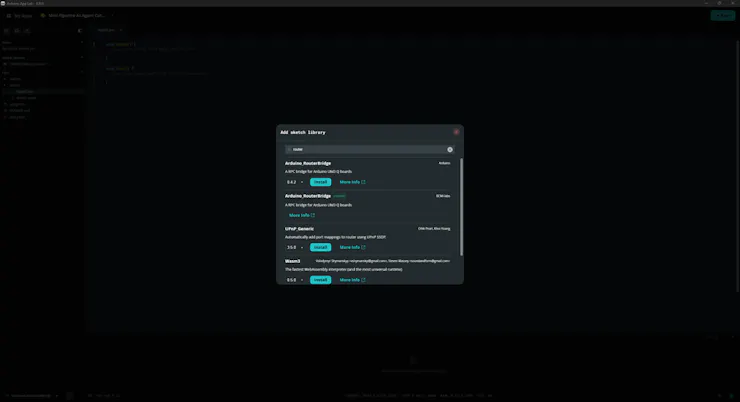
#️⃣ Then, I installed the required sketch libraries. Thankfully, all libraries were available in the provided App Lab library collection, so I did not need to modify any libraries due to incompatibilities.
#️⃣ If you encounter errors regarding the Arduino_RouterBridge library, download it manually since it was removed from the later versions of the bundled Zephyr platform (Arduino UNO Q Board).
📚 DRV8835MotorShield | Inspect
📚 Adafruit NeoPixel | Inspect
📚 Arduino_RouterBridge | Inspect
![]()
![]()
![]()
#️⃣ To develop mini-figurine cataloger features, I added these Bricks.
Basically, Bricks are pre-configured services and Docker containers to add various features to a custom App Lab application. Each Brick provides a specific set of capabilities that are executed by the Qualcomm MPU (Linux) and can be accessed by the Python script (backend) of the application via the built-in high-level APIs.
![]()
![]()
![]()
-
3Step 2: Collecting audio samples directly from UNO Q via the Edge Impulse CLI
Since some of my mini-figurines do not have a stable base, they are prone to falling while the rotary platform swivels. Thus, I decided to build an audio classification model to detect figurine falls in order to suspend the cataloging process to let the user reposition the figurine and resume the process without producing unsolicited figurine photographs.
Fortunately, the Logitech Brio 4K USB webcam comes with a built-in microphone. Thus, I was able to collect audio samples directly from the UNO Q and run the trained audio classification model on the Arduino App Lab without needing a secondary microphone.
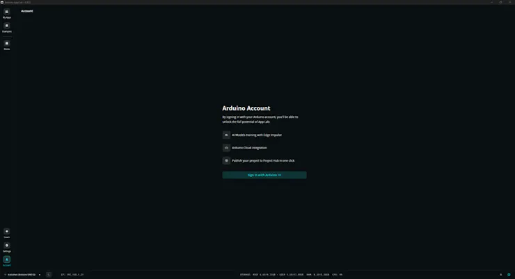
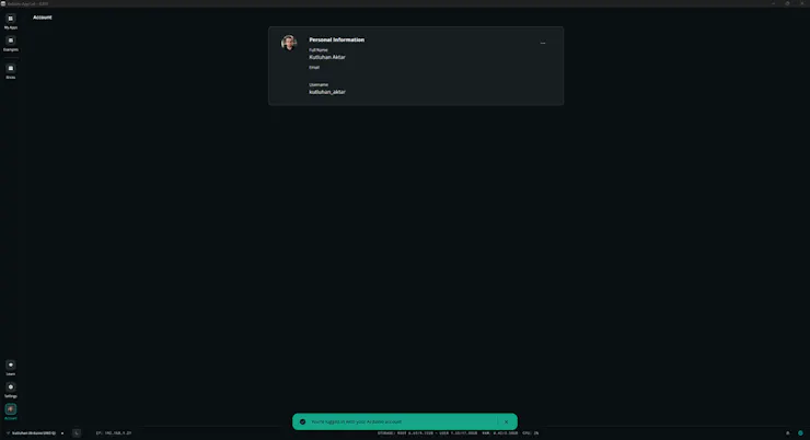
#️⃣ First, I signed in to my Arduino account on the Arduino App Lab, which is required to deploy and run EI models on the App Lab through the provided Bricks, in this case, the Audio Classification Brick.
![]()
![]()
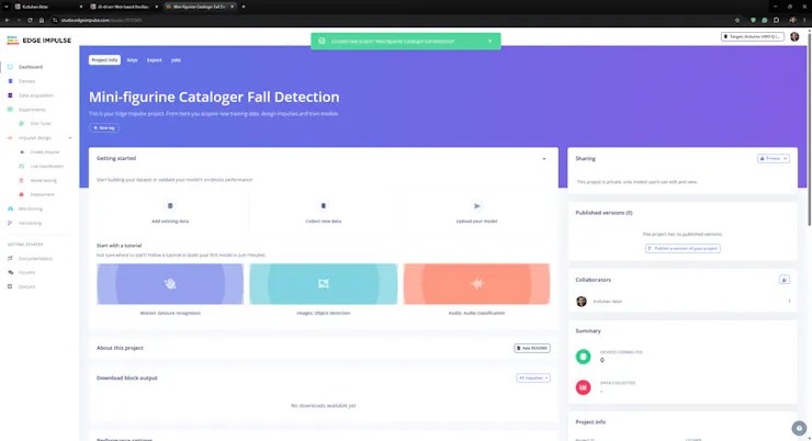
#️⃣ Then, I created a new project on my Edge Impulse Enterprise account and selected the target development board as Arduino UNO Q.
![]()
![]()
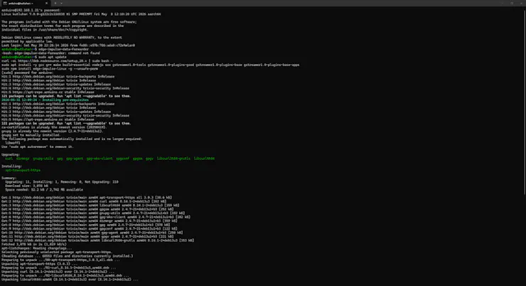
#️⃣ Although there is a built-in pipeline to obtain trained Edge Impulse models, the App Lab does not let the user collect samples directly from Arduino UNO Q yet. Thus, I set up the Edge Impulse CLI on the UNO Q via the built-in App Lab terminal to be able to access video and audio streams produced by the Brio webcam on the Edge Impulse Studio.
sudo apt updatecurl -sL https://deb.nodesource.com/setup_20.x | sudo bash -sudo apt install -y gcc g++ make build-essential nodejs sox gstreamer1.0-tools gstreamer1.0-plugins-good gstreamer1.0-plugins-base gstreamer1.0-plugins-base-appssudo npm install edge-impulse-linux -g --unsafe-per
![]()
![]()
#️⃣ After setting up the Edge Impulse CLI, I connected to my Edge Impulse account, selected the associated project, assigned the Logitech Brio webcam's built-in microphone as the primary audio source, and name the device.
edge-impulse-linux
![]()
![]()
![]()
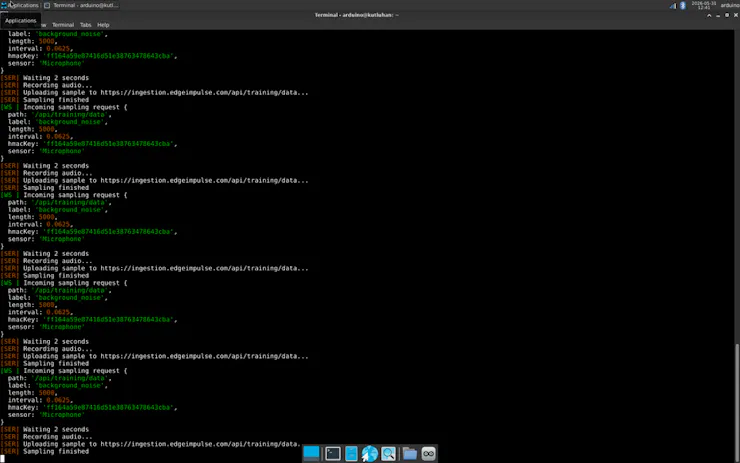
#️⃣ Nonetheless, as I was trying to collect audio samples on the built-in App Lab terminal, I encountered some connection issues. Thus, I resumed collecting audio samples on the native terminal in the SBC mode.
![]()
![]()
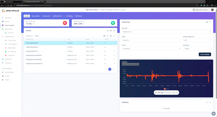
#️⃣ After moving to the SBC mode, I was able to see the UNO Q on the Edge Impulse Studio without any connection errors and start collecting audio samples while providing labels and sample durations.
![]()
![]()
![]()
#️⃣ Since the gearmotors driving the worm gear and the custom GT2 pulley work continuously while cataloging the target mini-figurines, I collected audio of gearmotors turning as the background noise (normal) samples. I chose the background noise sample duration as 5 seconds, as this state should be the norm for the neural network model.
![]()
![]()
![]()
![]()
![]()
![]()
![]()
#️⃣ Then, I collected audio of figurines falling at different angles and heights to construct an extensive dataset. I selected the sample duration as 2 seconds since the falling happens abruptly without many repetitions.
![]()
![]()
![]()
![]()
![]()
After collecting training and testing audio samples for both labels, I completed my dataset for detecting figurine falls.
- background_noise
- model_fall
To utilize the advanced AI tools provided by Edge Impulse, you can register here.
For further information, you can inspect this audio classification model on Edge Impulse as a public project.
![]()
-
4Step 2.1: Building and training an audio classification model with Edge Impulse
An impulse (an application developed and optimized by Edge Impulse) takes raw data, applies signal processing to extract features, and then utilizes a learning block to classify new data.
For my application, I created the impulse by employing the Audio (MFE) processing block and the Classification learning block.
Edge Impulse supports splitting raw audio samples into multiple windows by adjusting the parameters of the Time series data inputs.
- Window size — size of data that will be processed per classification, in milliseconds
- Window increase (stride) — sliding window in milliseconds to go over longer samples
MFE (Mel Frequency Energy) signal processing block simplifies the generated raw audio windows, which contain a large amount of redundant information.
Classification learning block represents an officially supported Keras neural network model.
#️⃣ First, I opened the Impulse design ➡ Create impulse section and selected the mentioned blocks. I left the block configurations as defaults. To complete the impulse creation, I clicked Save Impulse.
![]()
![]()
![]()
#️⃣ To modify the raw audio features in the applicable format, I navigated to the Impulse design ➡ MFE section and clicked Save parameters to apply default settings.
![]()
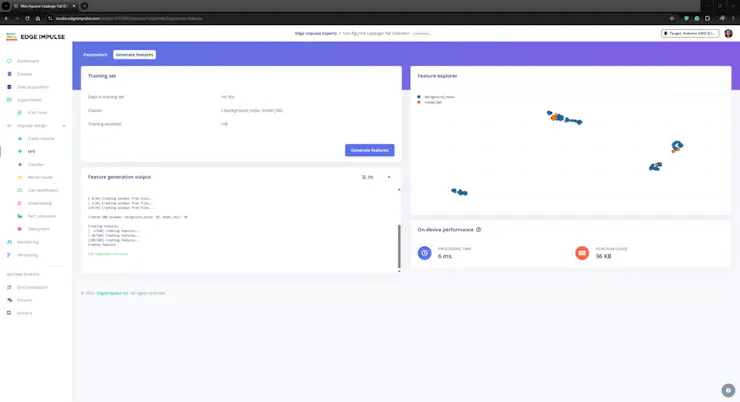
#️⃣ Then, I proceeded to click Generate features to extract the required features for training by applying the MFE signal processing block.
![]()
![]()
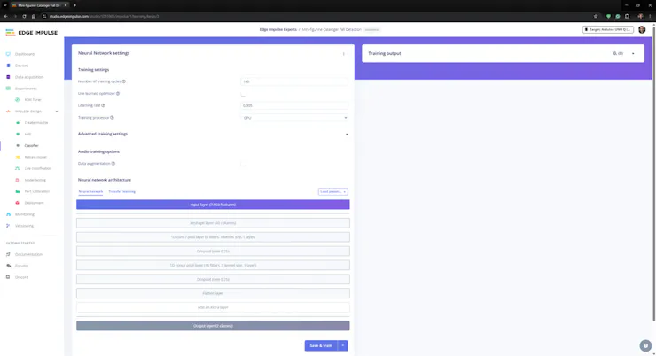
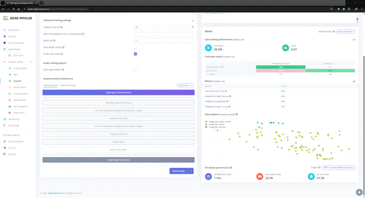
#️⃣ After extracting features successfully, I navigated to the Impulse design ➡ Classifier section and applied the default neural network settings and architecture to achieve reliable accuracy and validity.
#️⃣ After training the audio classification model, Edge Impulse evaluated the accuracy as 95.5%. This precision score, although really close to the final testing results, should be viewed as a narrow estimation due to the modest validation set.
![]()
![]()
![]()
![]()
![]()
-
5Step 2.2: Evaluating the model accuracy and deploying the validated model
#️⃣ First, to obtain the validation score of the trained model based on the provided testing samples, I navigated to the Impulse design ➡ Model testing section and clicked Classify all.
#️⃣ After applying the trained model to the testing samples, Edge Impulse evaluated the model accuracy as 100.00%.
![]()
![]()
![]()
![]()
#️⃣ To deploy the validated model optimized for my hardware, I navigated to the Impulse design ➡ Deployment section and searched for UNO Q.
#️⃣ I chose the Quantized (int8) model variant (optimization) to achieve the optimal performance while running the deployed model.
#️⃣ Finally, I clicked Build to deploy the model. However, contrary to the usual deployment procedure, I did not utilize the downloaded EIM binary since the Arduino App Lab provides a pipeline to link Edge Impulse projects to import deployed models directly.
![]()
![]()
![]()
#️⃣ As mentioned in the previous steps, I had already signed in to my Arduino account on the Arduino App Lab. Thus, I only needed to click Go to Arduino and open the App Lab to link this Edge Impulse project to my Arduino account via the built-in pipeline.
#️⃣ After linking the project, I navigated to the Audio Classification Brick configurations, installed my audio classification model for detecting figurine falls, and selected it as the primary Brick model.
![]()
![]()
![]()
![]()
-
6Continue reading the project tutorial
Inspect the full project instructions on Hackster:
Mini-figurine Cataloger and Listing Tracker
Automatic platform and slider movements to capture 360° figurine images. Scheduled listing tracking and feature-rich web interface on UNO Q.















Discussions
Become a Hackaday.io Member
Create an account to leave a comment. Already have an account? Log In.