Close
0%
0%

8-bit Workbench ED: hands-on with number systems

Explore the computer byte with this educational easy-to-solder kit. Toggle in 8 bits and see their decimal, hex or octal value. With game!

Similar projects worth following
Starting from
$
has orders / reviews
Ships from
Explore the computer byte with this educational easy-to-solder kit. Toggle in the eight bits and see their decimal, hexadecimal or octal value. Annotated LEDs help you to understand how number systems work and make it easy to do conversions. Powered by USB-C or a 9-volt battery. Game included!

Pre-order now on Lectronz!

for Retro Hobbyists

Altair-like input switches take you down memory lane. Select Octal mode, play the game and guess the bits. Recall how machines from the seventies did it. Want more? Explore the full 8-bit Workbench™ platform with clocks, byte full adders, hex keyboards and breadboards. 

for Programmers

Have it sitting around on your desk. Especially handy with the low-level work. What is the hex value of these bits? How many will fit in a nibble? Why is this backwards relative jump in assembly going wrong, have I miscounted?

in the Classroom

Enables focused learning by doing, on a dedicated device. A great STEM-kit, in the field of computer science, electronics or mathematics. Sample lessons are provided. A game is there for students that need the extra motivation.

The kit is an easy solder exercise with no tiny parts. Launch a course quickly by ordering a pre-assembled batch. Contact us for the possibilities.


Functionality

The mode button selects one of the three number systems (decimal, hexadecimal or octal) to be displayed by the three digits. Hold the button to turn the digits ON or OFF. Handy for training purposes. The active mode is indicated by a green SMD LED. Please note that the three digits look a little faint on the pictures, this is because of the photography, they are clear and strong in real life.

With a built-in game. The objective is to toggle in the bit-value of the random number that is displayed by the digits. Be quick and score higher! The game can be played in each of the three modes. It keeps a separate high score for each mode.

The board operates at 5V, directly from USB-C or powered from a battery source. An input voltage of 6.5V to 12V is supported and is further regulated on the board. This means a 9-volt block battery can be used or two 18650 Li-Ion batteries. The kit comes with a 9-volt battery clip. It can be stowed away nicely at the back using an integrated cable reel.

At the core of the board there is a microcontroller, the little black rectangle with 28 shiny legs. This little computer runs at 4 MHz and has a small memory of around 2 KB. It comes pre-programmed to let the board operate as it is intended to. For advanced use it can be reprogrammed using the ICSP header connector.

What's in the box?

Provided as an easy to solder kit, it includes:

  • Printed Bill of Materials (BoM),
  • Schematics,
  • Assembly Manual,
  • Operation Manual (with sample lessons),
  • Main PCBA with pre-soldered tiny parts (like the USB-C connector and SMD parts, see the BoM),
  • Front panel PCB that holds the toggle switches (can be left out if you prefer slide switches),
  • Microcontroller, flashed to the latest firmware.

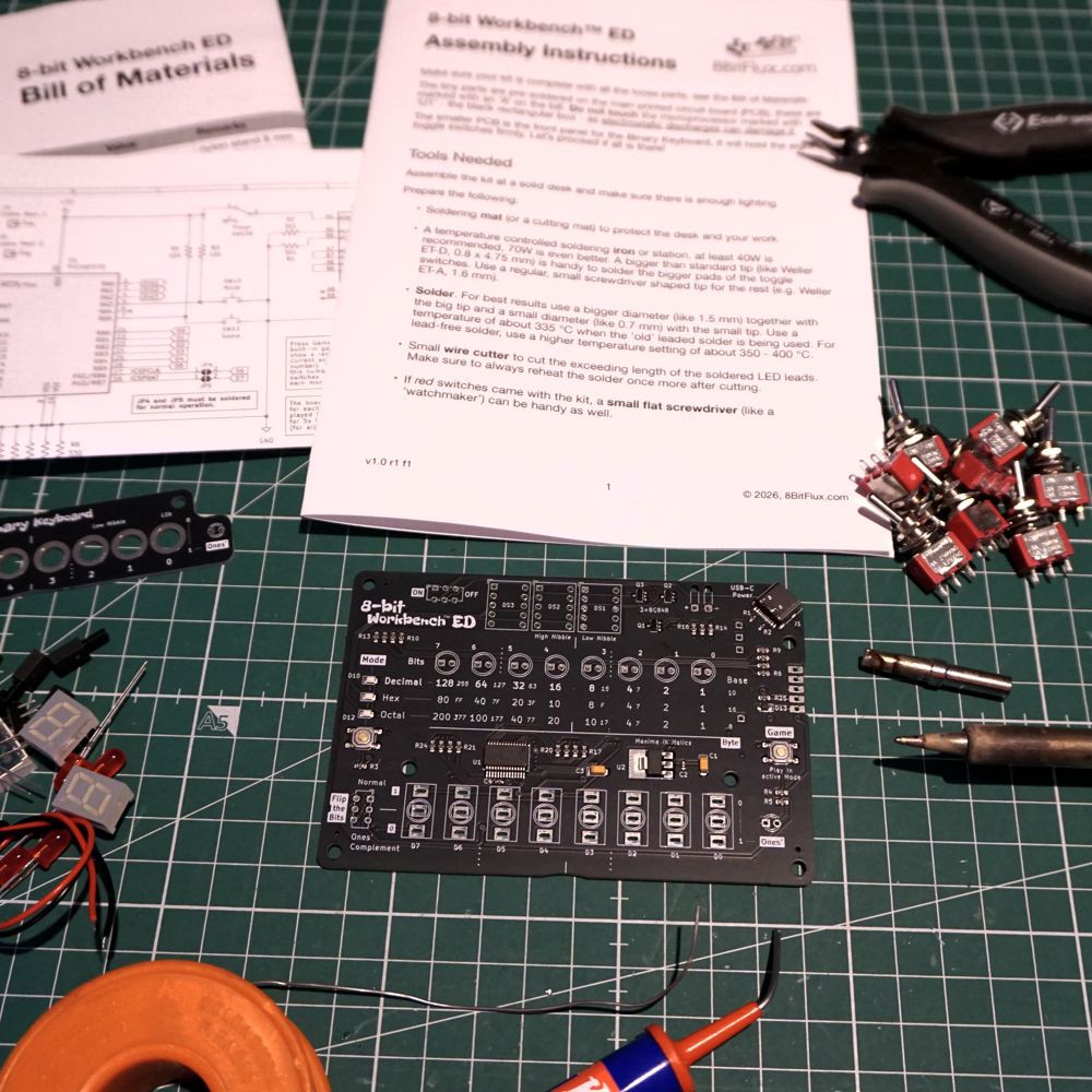
Plus all parts that have to be soldered, like the LEDs, switches and digits. See the BoM for details. The provided manual guides you trough the process of building it in 12 easy to follow steps. Batteries are not included.

Pre-order now on Lectronz!

8bitWorkbenchEDSchematics.pdf

Schematics

Adobe Portable Document Format - 351.28 kB - 07/20/2026 at 18:54

Preview

8bitWorkbenchEDBoM.pdf

Bill of Materials

Adobe Portable Document Format - 102.66 kB - 07/20/2026 at 18:54

Preview

8bitWorkbenchEDAssembly.pdf

Assembly Instructions

Adobe Portable Document Format - 75.40 kB - 07/20/2026 at 18:54

Preview

  • 1 × PIC16F570 The heart of the device.

  • Firmware source v1.0 released

    Nijssen34 minutes ago 0 comments

    The firmware source v1.0 for the PIC16F570 micro-controller has been released here under the the GNU General Public License version 3. It is available as a zip file containing the MPLAB X IDE project, which contains the C-code and .hex binary. 

    Those who want to experiment further can re-flash it using the ICSP header on the board. Make sure to break the two solder jumpers (JP4 & JP5) before doing so. It can be flashed by USB using a PICKit 3 programmer for example. 

    This way you can create your own games (maybe Snake?), display other/custom number systems or create something else like an interactive periodic table...

    Thanks goes out to Alexander Fakoo, creator of the Siekoo Alphabet. This 7-segment alphabet is used in the game to output messages.

  • First ones to ship next month?

    Nijssen6 days ago 0 comments

    When we reach the threshold of 10 units, that is! The campaign is halfway now, so pre-order yours today.

    All orders will be processed in sequence: first in, first to ship. Preparing the buy-in of all the parts. Have set the lead time to 70 days, to give me some slack, but try to cut that in half. 

    Finishing off the code (that will be open sourced) and operation manual that will contain example lessons to get you (or your students) going. Below is a concept of Lesson 0 from the manual, it is about Number Systems. There will be a total of 8 (funny figure) lessons provided.

  • Open source incoming...

    Nijssen08/05/2026 at 08:26 0 comments

    Got some questions about this lately, for those who want to run their own code on this board or make adaptations. For example to create support for other number systems or to write your own game.

    The C-code that runs on the PIC16F570 will be open sourced. It needs some cleaning and documentation first, then it will be made available as a MPLAB X IDE project containing the C-code. 

    All boards provided in the kit will be flashed already to the latest firmware.

    Those who want to experiment further can re-flash it using the
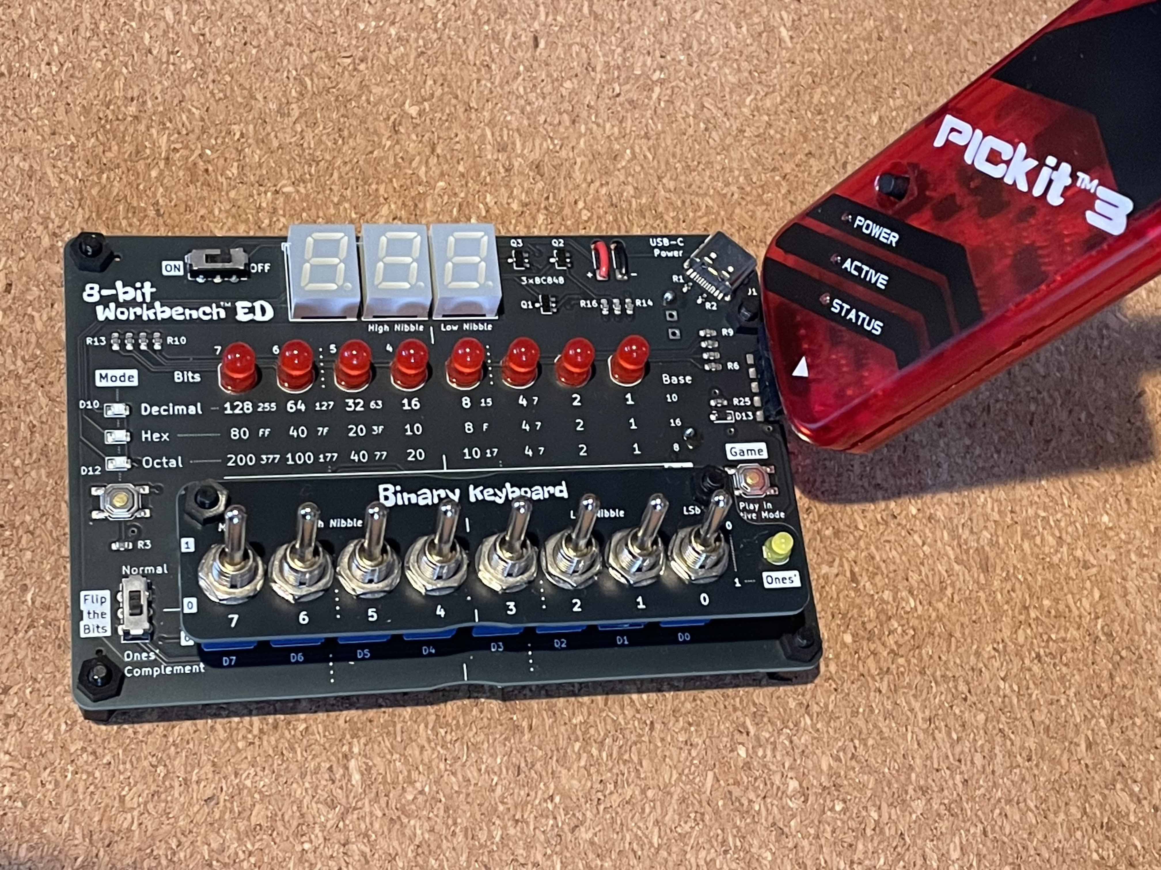
    ICSP header on the board. Make sure to break the two solder jumpers (JP4 & JP5) before doing so. It can be flashed by USB using a PICKit 3 programmer for example, see the image below.

  • Video demonstrating the 8-bit Workbench ED!

    Nijssen08/01/2026 at 18:48 0 comments

View all 4 project logs

View all instructions

Enjoy this project?

Share

Discussions

Similar Projects

Does this project spark your interest?

Become a member to follow this project and never miss any updates