Nijssen
-
Firmware source v1.0 released
an hour ago • 0 commentsThe firmware source v1.0 for the PIC16F570 micro-controller has been released here under the the GNU General Public License version 3. It is available as a zip file containing the MPLAB X IDE project, which contains the C-code and .hex binary.
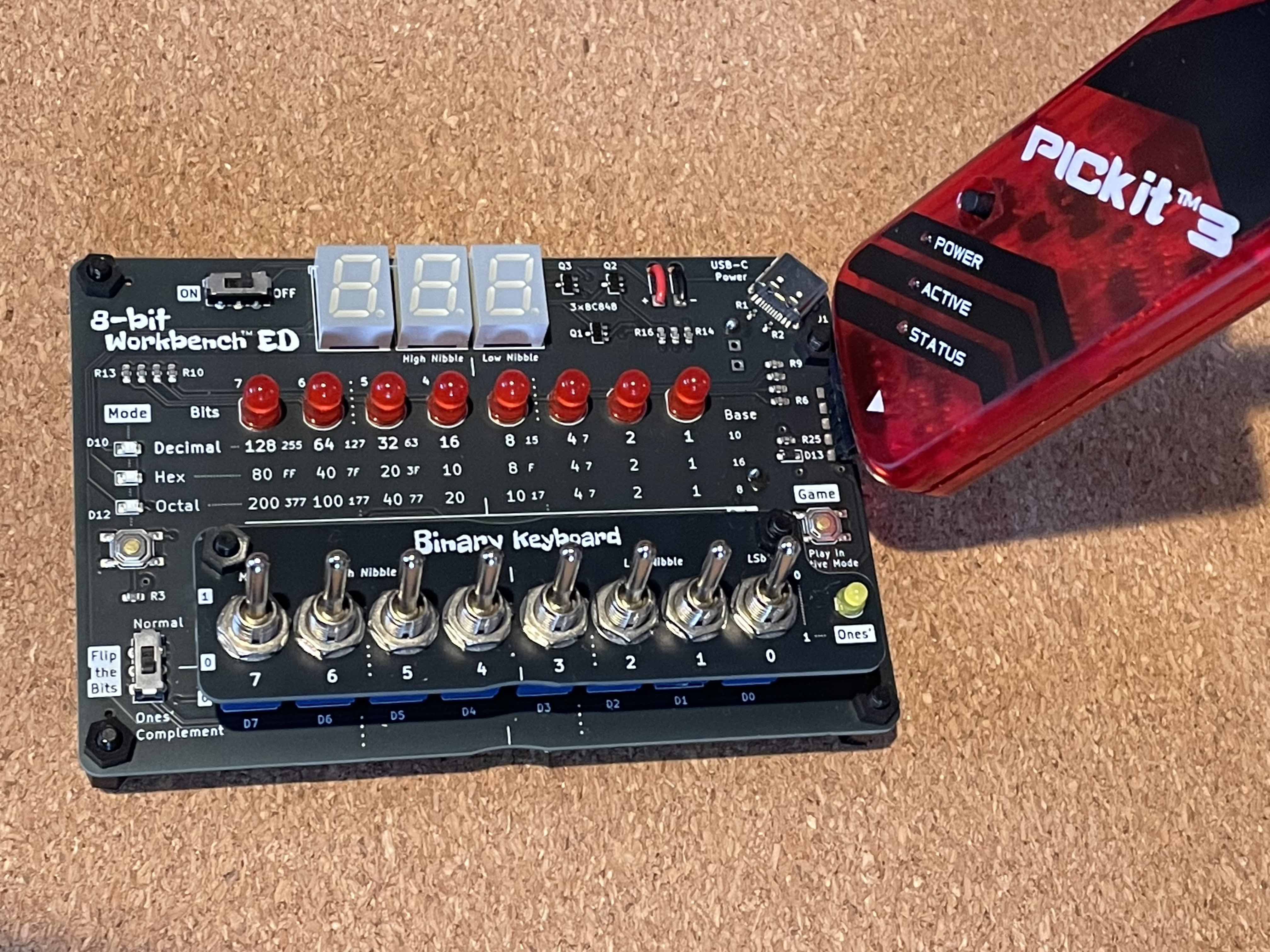
Those who want to experiment further can re-flash it using the ICSP header on the board. Make sure to break the two solder jumpers (JP4 & JP5) before doing so. It can be flashed by USB using a PICKit 3 programmer for example.
This way you can create your own games (maybe Snake?), display other/custom number systems or create something else like an interactive periodic table...
Thanks goes out to Alexander Fakoo, creator of the Siekoo Alphabet. This 7-segment alphabet is used in the game to output messages.
-
First ones to ship next month?
6 days ago • 0 commentsWhen we reach the threshold of 10 units, that is! The campaign is halfway now, so pre-order yours today.
All orders will be processed in sequence: first in, first to ship. Preparing the buy-in of all the parts. Have set the lead time to 70 days, to give me some slack, but try to cut that in half.
Finishing off the code (that will be open sourced) and operation manual that will contain example lessons to get you (or your students) going. Below is a concept of Lesson 0 from the manual, it is about Number Systems. There will be a total of 8 (funny figure) lessons provided.
![]()
-
Open source incoming...
08/05/2026 at 08:26 • 0 commentsGot some questions about this lately, for those who want to run their own code on this board or make adaptations. For example to create support for other number systems or to write your own game.
The C-code that runs on the PIC16F570 will be open sourced. It needs some cleaning and documentation first, then it will be made available as a MPLAB X IDE project containing the C-code.
All boards provided in the kit will be flashed already to the latest firmware.
Those who want to experiment further can re-flash it using the ICSP header on the board. Make sure to break the two solder jumpers (JP4 & JP5) before doing so. It can be flashed by USB using a PICKit 3 programmer for example, see the image below.![]()
-
Video demonstrating the 8-bit Workbench ED!
08/01/2026 at 18:48 • 0 comments
8-bit Workbench ED: hands-on with number systems
Explore the computer byte with this educational easy-to-solder kit. Toggle in 8 bits and see their decimal, hex or octal value. With game!