 youkito1991
-
1Project Details
![]()
Most adjustable bench power supplies today are built around integrated circuits such as operational amplifiers or dedicated regulator ICs. While these solutions are compact and efficient, they often hide the fundamental principles behind voltage regulation and current limiting.
For this project, I wanted to take a different approach.
The goal was to design a fully functional laboratory power supply using only discrete transistors, without relying on any integrated circuits. Every stage of the regulation loop—from voltage control to current limiting—is implemented using individual transistor circuits.
The result is a linear power supply capable of delivering an adjustable output from 0 to 40 volt DC with an adjustable current limit from 0 to 5 ampere.
-
2Why Build It This Way?
![]()
This project is primarily intended as an educational design.
![]()
![]()
Instead of treating the power supply as a "black box," the circuit demonstrates how individual transistors can be combined to create:
- Voltage regulation
- Current sensing
- Current limiting
- Feedback control
- Power amplification
Building the circuit also provides a much deeper understanding of classic analog electronics than simply connecting a regulator IC.
-
3Main Features
![]()
- Output Voltage: 0–40V DC
- Current Limit: 0–5A
- Fully adjustable voltage and current
- 100% discrete transistor design
- No operational amplifiers
- No voltage regulator ICs
- No controller ICs
- DIY-friendly PCB layout
-
4Circuit Architecture
![]()
![]()
![]()
![]()
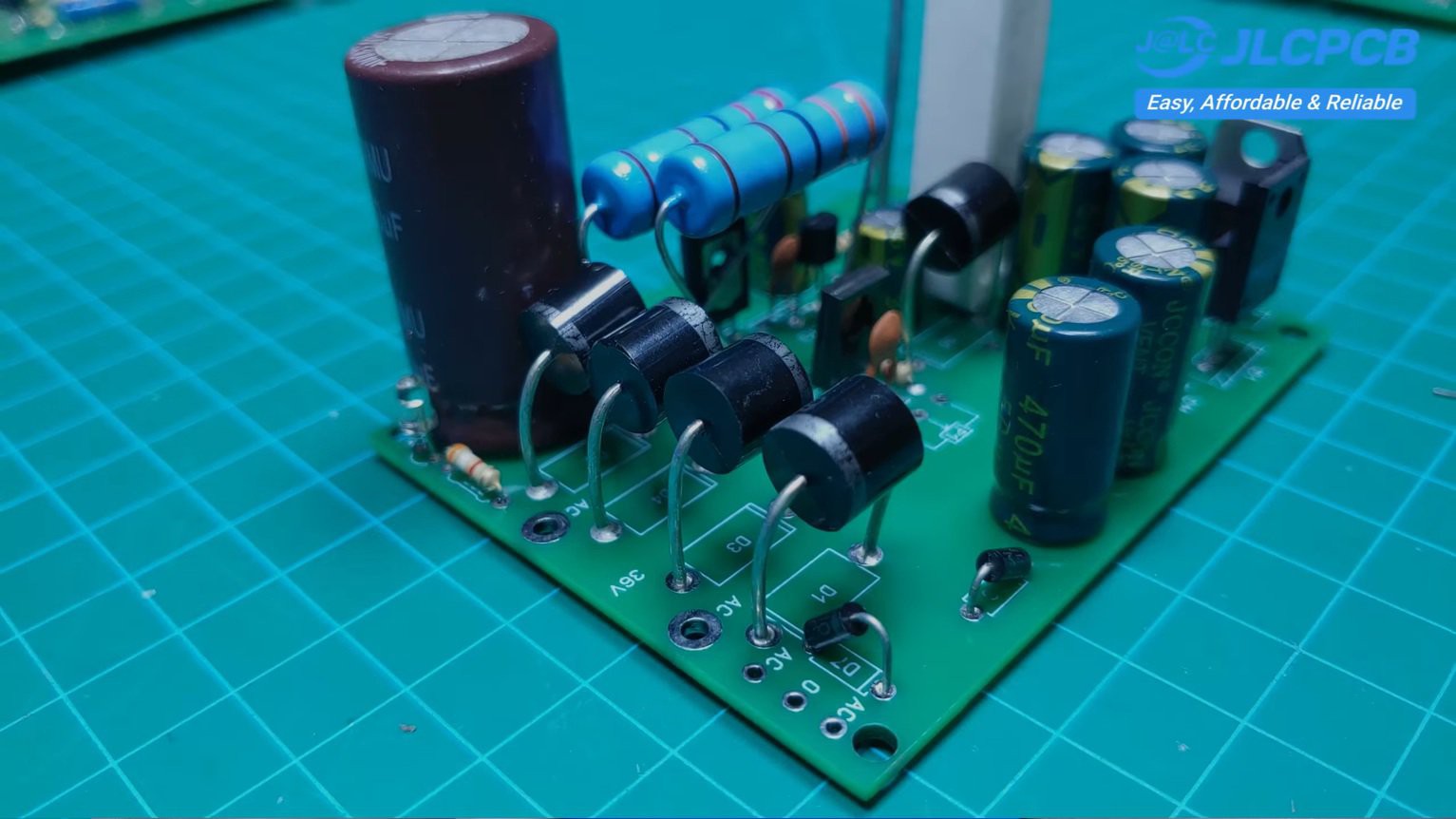
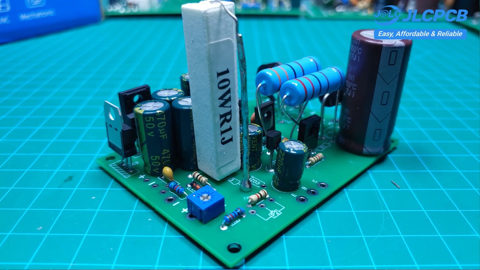
The design consists of several functional sections:
- AC input and bridge rectifier
- Large capacitor filter
- Zener reference network
- Transistor voltage regulator
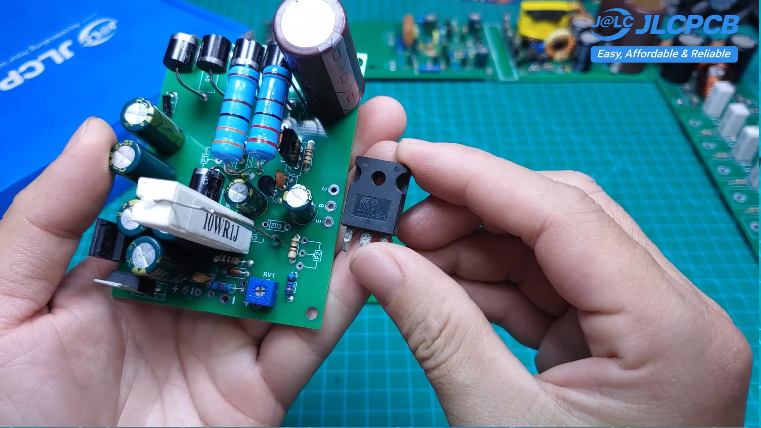
- Current sensing using a 0.1Ω / 10W shunt resistor
- Current limiting circuit
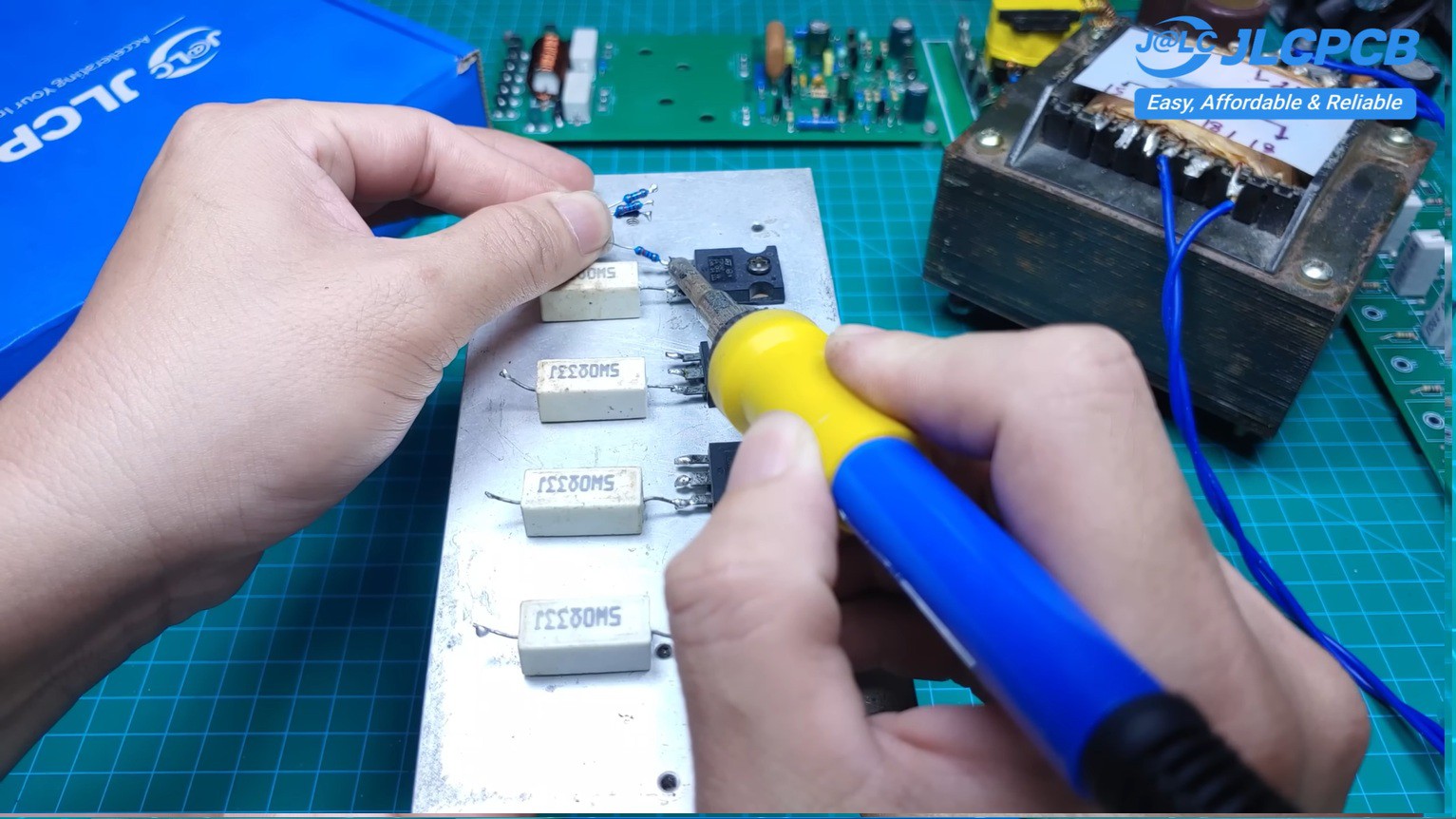
- Parallel power transistor output stage
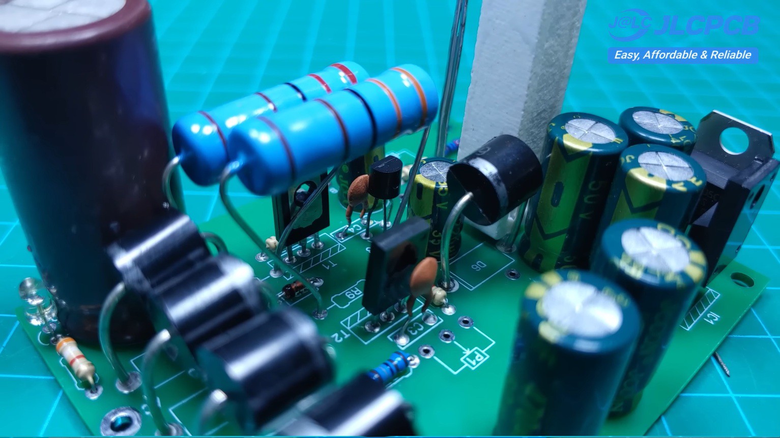
The control circuit uses common transistors such as BD137 and BD138, while the output stage uses multiple TIP142 transistors mounted on a large heatsink.
Emitter resistors ensure proper current sharing between the parallel output devices.
-
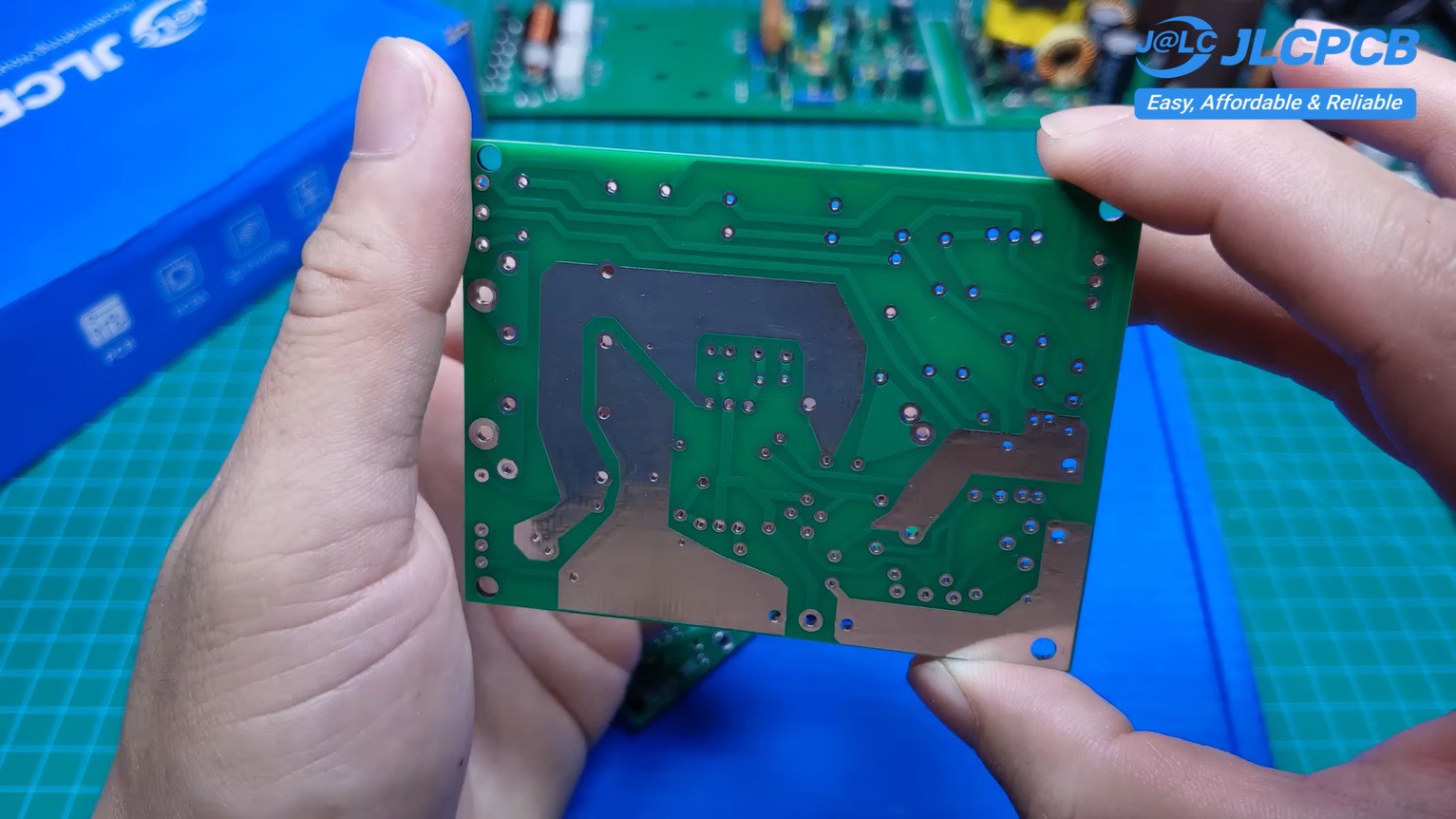
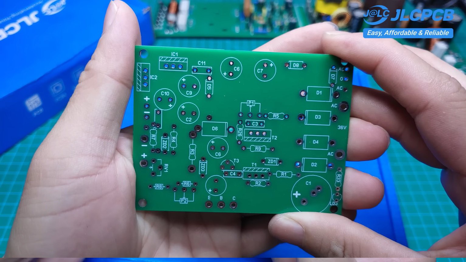
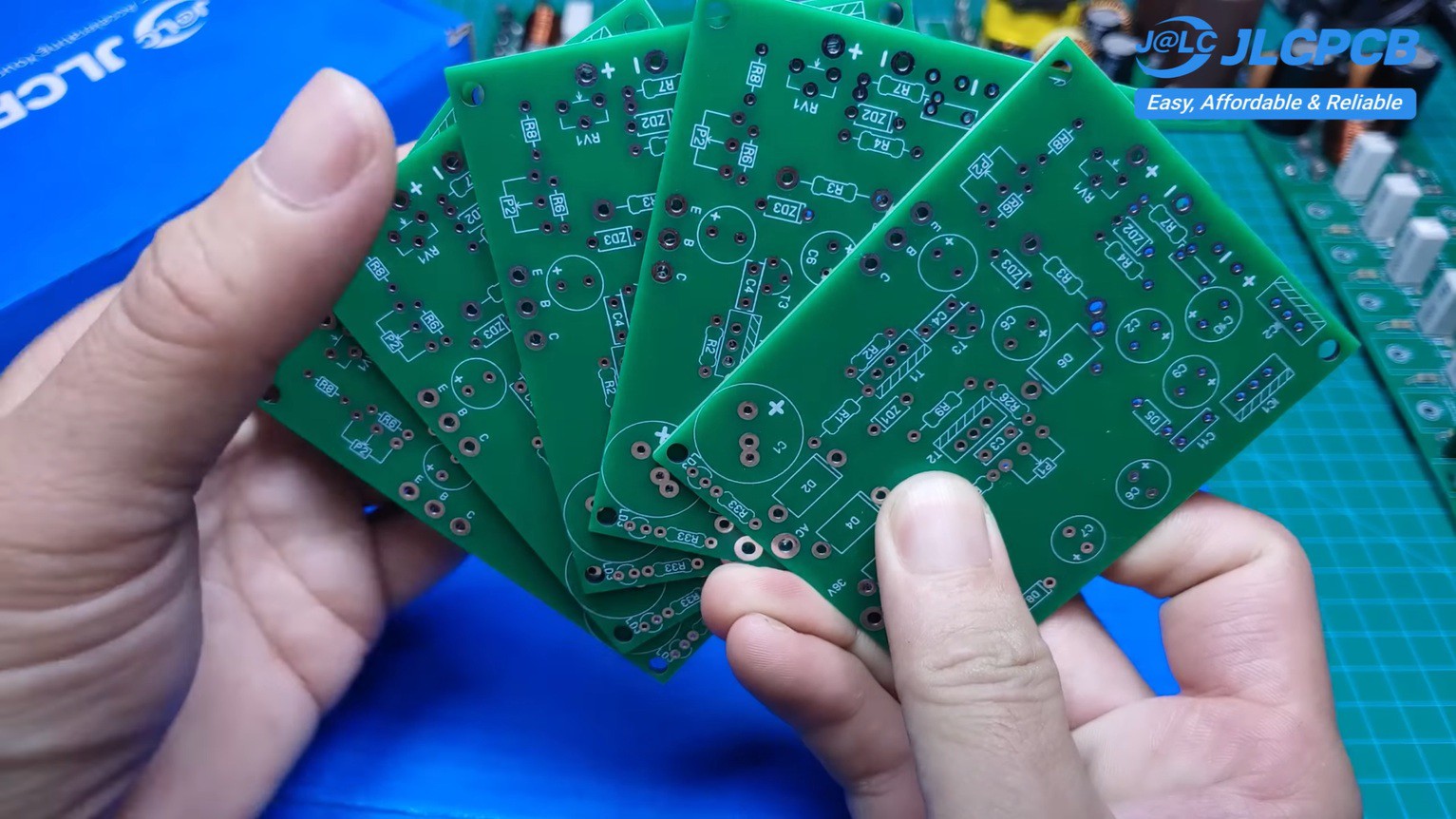
5PCB Design
![]()
The PCB was designed specifically for DIY assembly.
Special attention was given to:
- High-current copper routing
- Component spacing
- Easy soldering
- Simple troubleshooting
- Clean board layout
The boards were manufactured by JLCPCB, and the fabrication quality was excellent.
-
6Testing
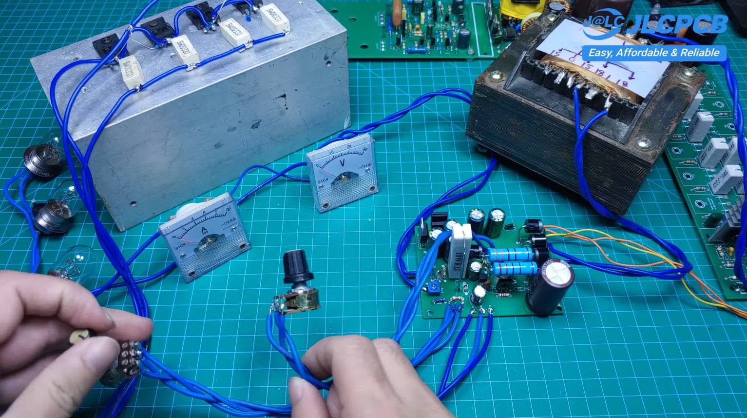
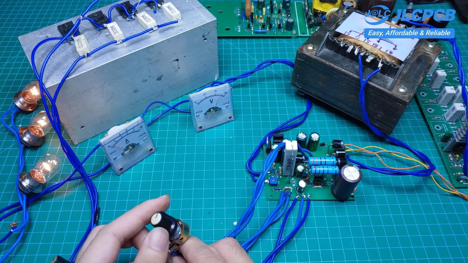
The prototype was tested using:
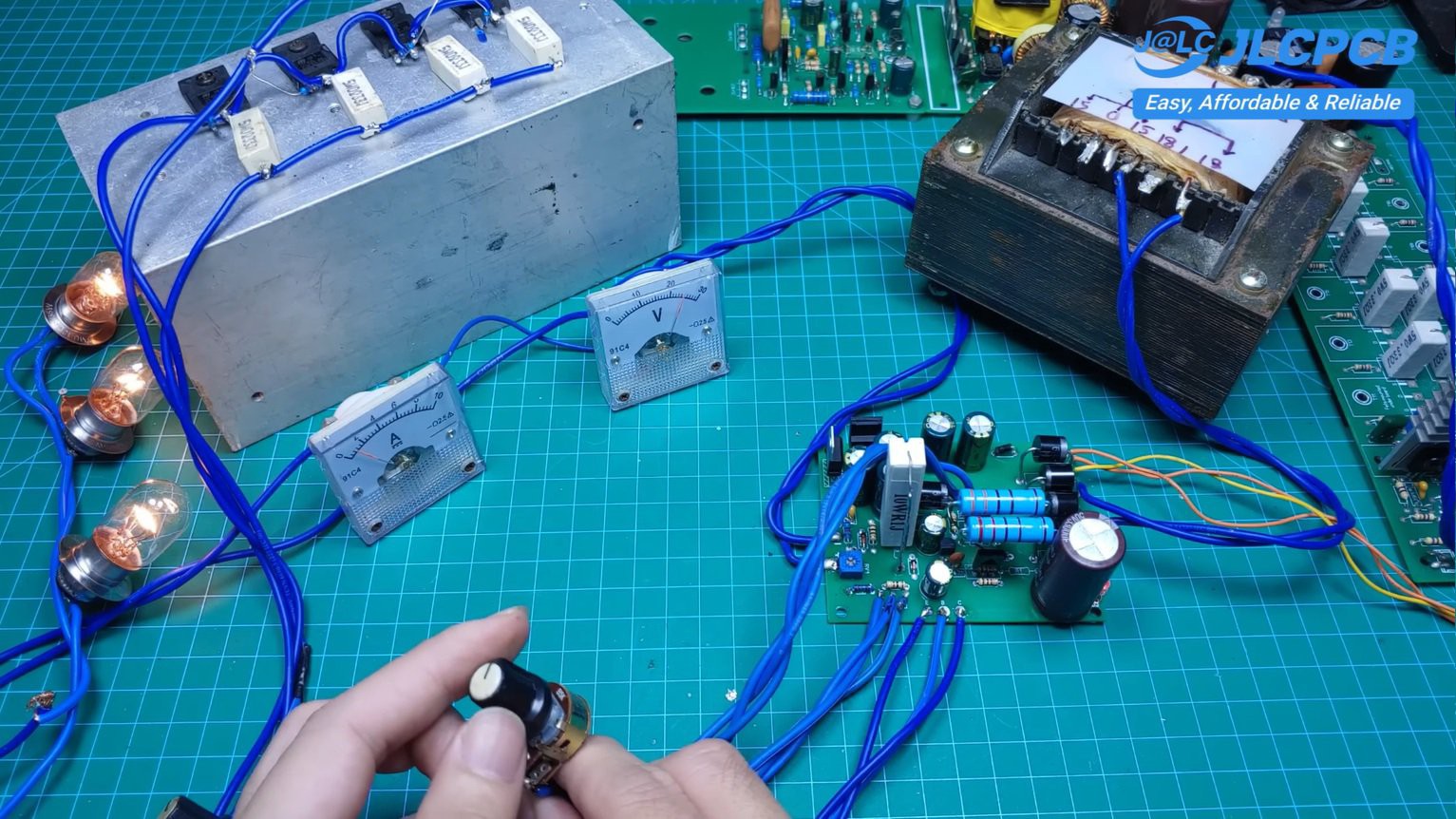
![]()
- 30V AC transformer
- Approximately 40V DC after rectification
- Three 12V lamps connected in series as the load
- Digital voltmeter and ammeter
Testing confirmed smooth voltage adjustment and reliable current limiting across the full operating range.
-
7Future Improvements
Although the current design performs well, there are several features that could be added in future revisions:
- Digital voltage/current display
- Temperature-controlled cooling fan
- Output protection relay
- Short-circuit indicator
- Modular front panel design
-
8Final Thoughts
Designing a complete adjustable power supply without using a single integrated circuit was both challenging and rewarding.
Although discrete transistor circuits require more components and careful tuning, they offer an excellent opportunity to understand how classic analog power supplies really work.
If you're interested in analog electronics or simply enjoy building circuits from first principles, I hope this project inspires you to try your own discrete transistor designs.
Feedback, suggestions, and improvements are always welcome. Happy building!
Adjustable 0–40V, 0–5A Linear Power Supply
I want to share a fully adjustable linear bench power supply that I designed,built completely from scratch using only discrete transistor
Discussions
Become a Hackaday.io Member
Create an account to leave a comment. Already have an account? Log In.