 iliasam
Finally I get all electronic parts, so it's time to assemble PCB!
Photo of components used:
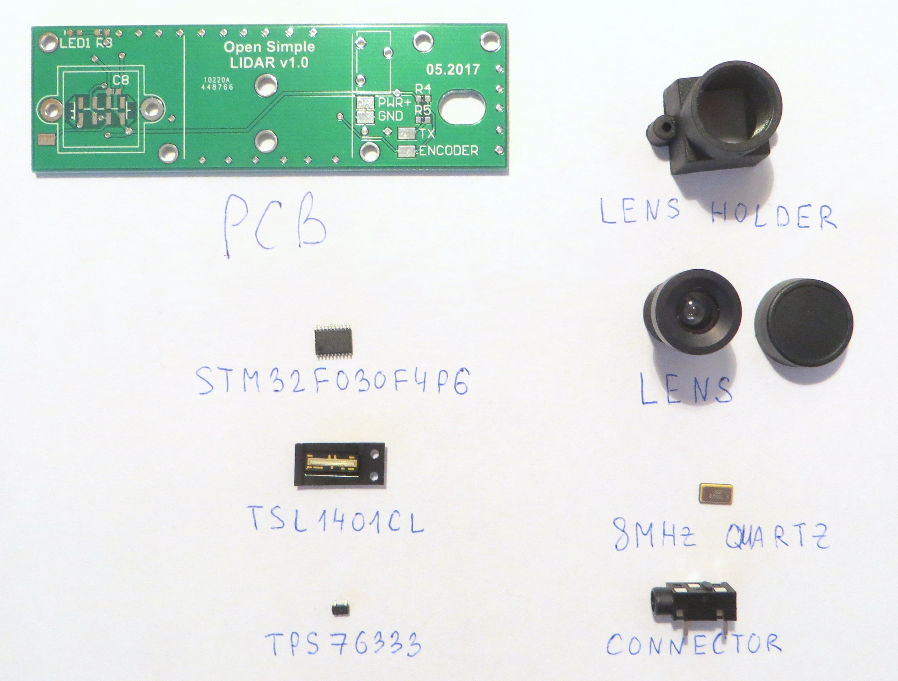
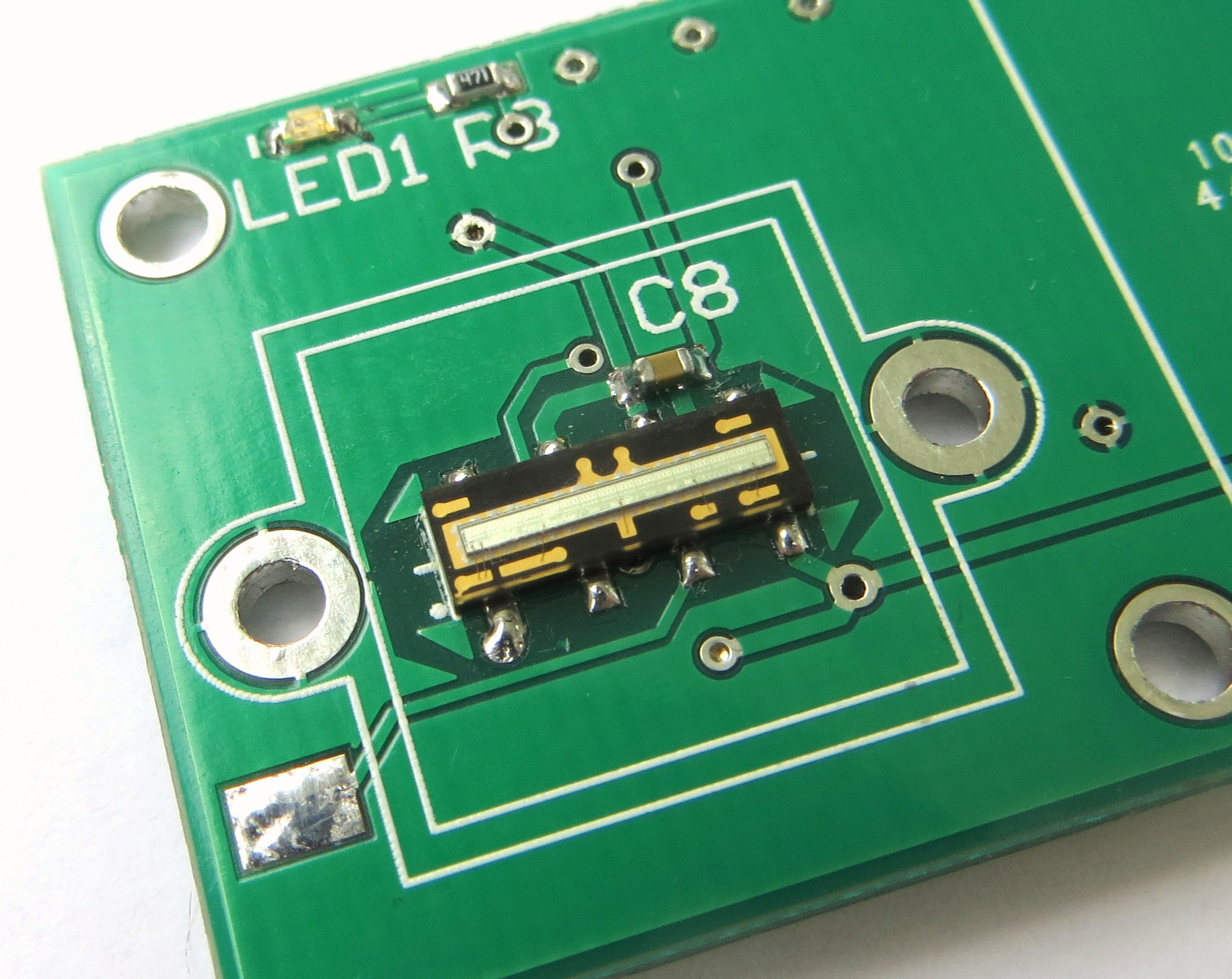
Most of them are easy enough to solder. The exception is light sensor - TSL1401CL; because pads of this sensor are placed under it's body.
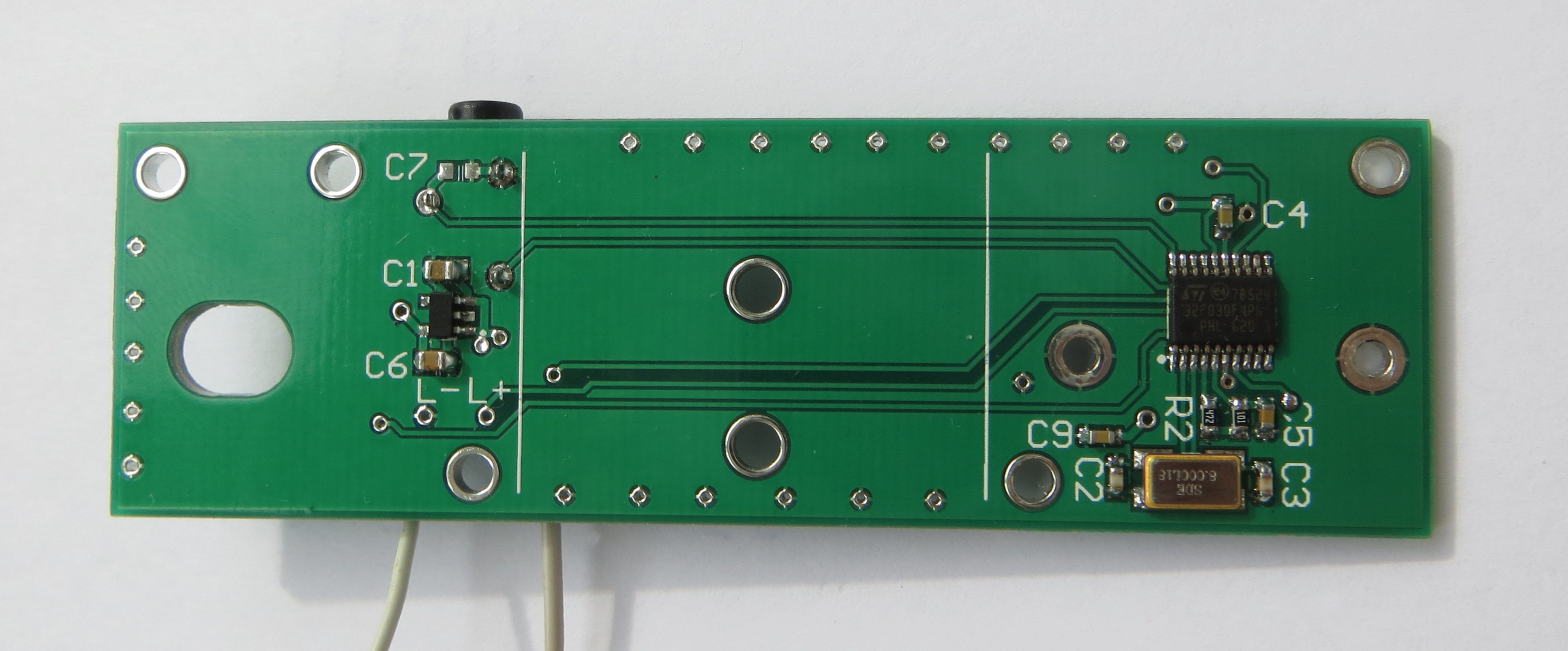
Photo of assembled PCB:
Close view of soldered TSL1401:
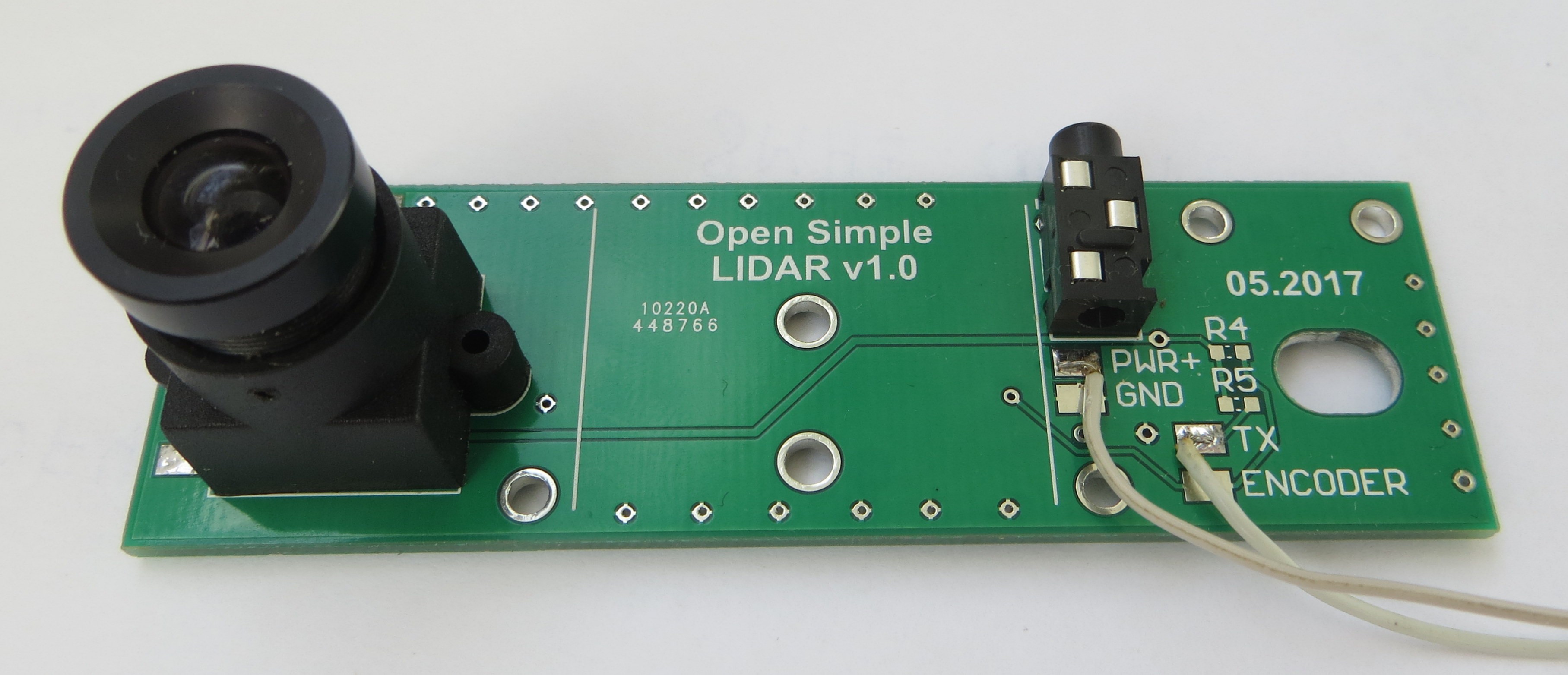
3.5 mm Jack connector is used for STM32 programmer connection.
ST-Link utility found STM32 - so the next step is it's programming.
Firstly I need to run capturing data from light sensor.
P.S. I have updated Github files - I added some models, PCB schematic, gerber files.
Discussions
Become a Hackaday.io Member
Create an account to leave a comment. Already have an account? Log In.