For the power source of the tablet, one of the best options is to harvest the power circuit and lithium cell from a power bank. Here, I used a PD power bank that I normally use for charging my iPhone and other devices. It can provide both power input and power output through its USB Type-C port, along with a stable 5V 3A output from its USB port.
Using a prying tool, we started opening the power bank. I didn't have a proper pry tool available, so I used the back side of a pair of tweezers.
By inserting it along the seam of the enclosure and applying a bit of pressure, the two halves of the body started separating.
The enclosure was held together using snap locks, so once we created an opening on one side, we inserted our pry tool into the gap and moved it along the edge to completely remove the lid.
Doing that completely separated both parts. The circuit was secured in place with M1.8 screws, which we removed.
The battery was also secured with adhesive tape, so by applying a little pressure, it came off as well.
This was a MagSafe charger, so it also included a charging coil, which we removed from the circuit.
As a result of this harvesting process, we ended up with a 10,000 mAh battery and a power circuit capable of powering our display and Raspberry Pi setup.
2
POWER SOURCE ASSEMBLY
After harvesting the lithium-polymer cell and charger circuit from the power bank, we extended the battery wires by desoldering the original wires and replacing them with longer ones.
We connected the battery positive terminal to the B+ pad on the circuit and the battery negative terminal to the B- pad.
Next, we soldered two output wires to the USB port's 5V and GND terminals. For connecting these output wires to the Raspberry Pi header pins, we added a CON3 female header connector to the 5V and GND wires.
With this header connector, we can simply plug it onto the Raspberry Pi's GPIO header 5V and GND pins, which power the entire setup.
3
IPOD UI
The software and UI for this project were developed with the help of my friend Aahan Sharma, who handled the application development. You can find his GitHub repository linked below.
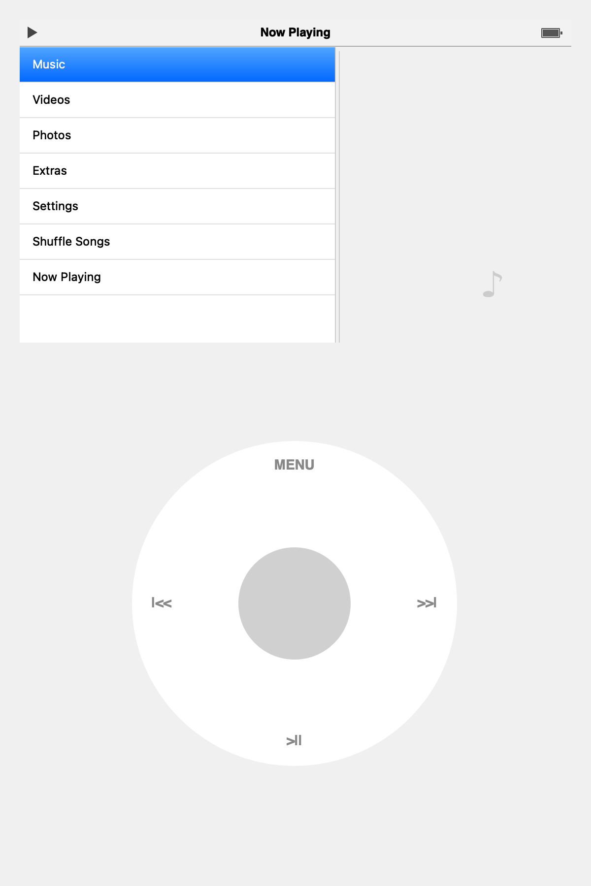
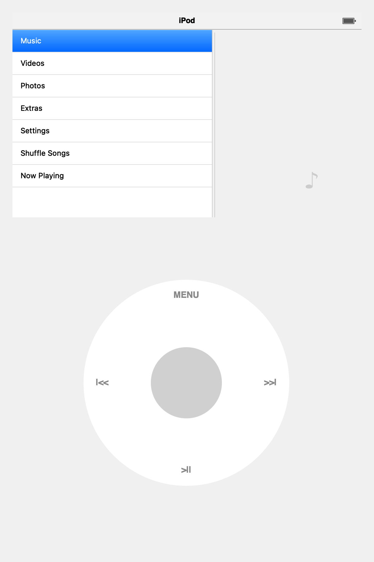
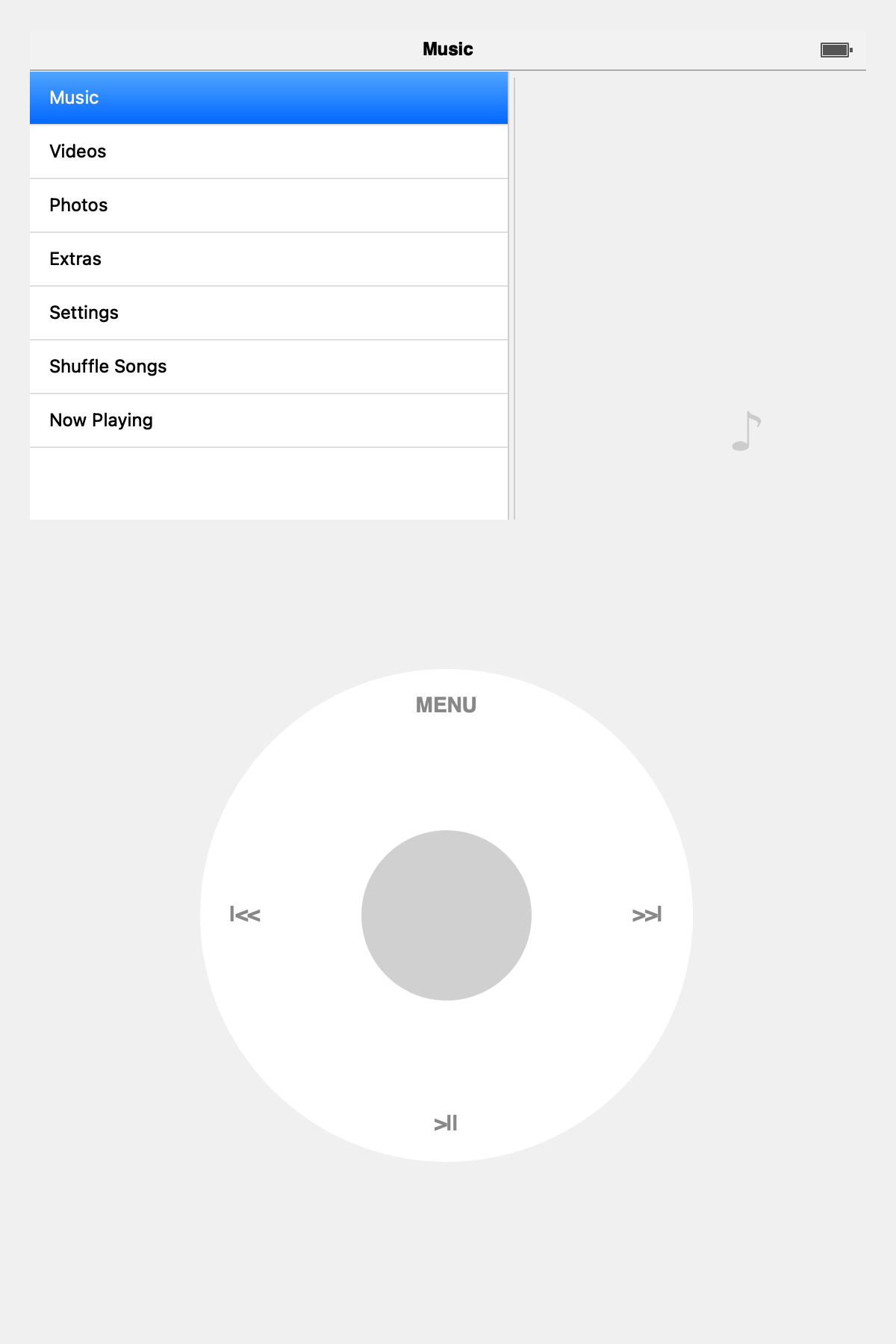
The goal was to recreate the feel of the original iPod experience as closely as possible. The interface features authentic sliding stack navigation, where nested menus animate left and right just like the original firmware, along with a fully emulated click wheel supporting rotational scrolling and the classic five-button controls. The media library is scanned in the background using Mutagen, automatically detecting newly added MP3 files, while python-vlc provides hardware-accelerated audio and video playback for smooth, low-latency performance.
The codebase is organized into three main sections: the core logic (library.py and player.py), the UI components (iPod_screen.py, now_playing.py, sliding_stack.py, and click_wheel.py), and the main application entry point (main.py), making the project modular and easy to extend.
Main Application and Background Thread
In 'main.py ', we initialise the Qt application and set up our primary UI elements: the top screen and the bottom click wheel. 'QThread' runs continuously in the background to scan the 'music/' folder for changes without freezing the UI
# snippet from main.pyclass IPodApp(QMainWindow):def __init__(self):super().__init__()self.setWindowTitle("iPod Classic - Pi CM5")self.setFixedSize(600, 900)# 1. Top Screenself.screen = IPodScreen(self.library, self.player)layout.addWidget(self.screen, stretch=2)# 2. Bottom Click Wheelself.wheel = ClickWheel()layout.addWidget(self.wheel, stretch=3)# Connect signalsself.wheel.scrolled.connect(self.screen.handle_scroll)self.wheel.clicked.connect(self.screen.handle_click)
Sliding Nav Menu
The core of the iPod experience is the sliding menus. We built a custom 'SlidingStackWidget' 'ui/sliding_stack.py' that uses Qt 'QPropertyAnimation' to smoothly slide 'QWidget' pages in from the left or right when navigating
Screen States and Nav
The 'IPodScreen' 'ui/ipod_screen.py' acts as the state machine for the UI; it pushes and pops different menu lists using a 'menu_history' stack to remember where the user came from.
We use 'python-vlc' for robust media decoding; found in 'core/player.py' it also handles a fallback for Mac testing via 'afplay '. The player integrates with the 'NowPlayingScreen' to sync progress bars and elapsed times.
Running the App
Install the dependencies via 'pip'
pip install PyQt6 python-vlc mutagen numpy
Put some '.mp3' files in the 'music/' directory.
Run the main script.
python main.py
4
DESIGN
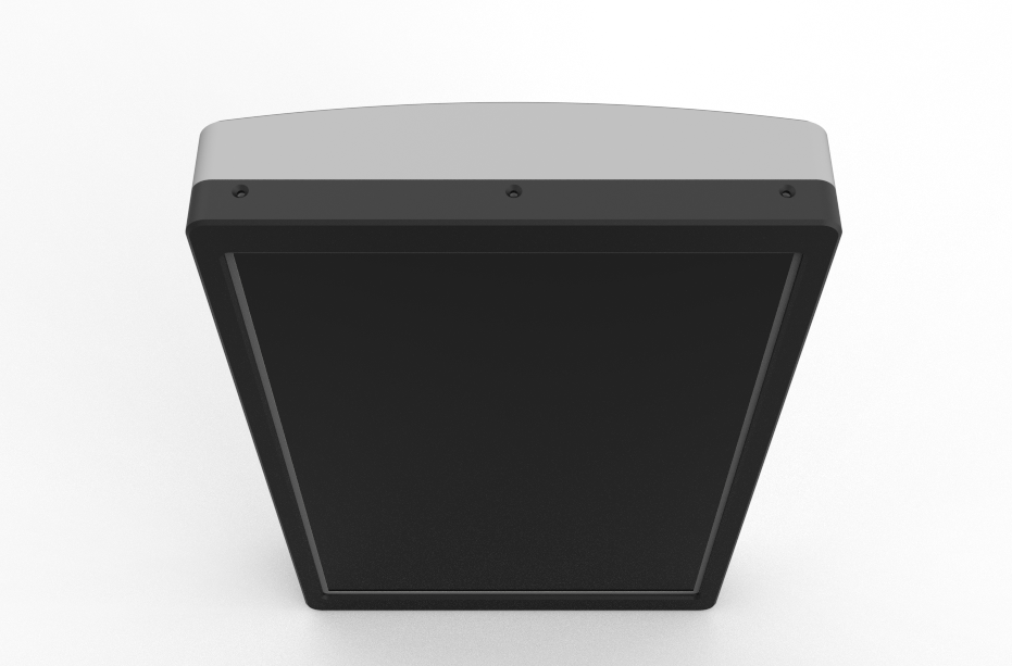
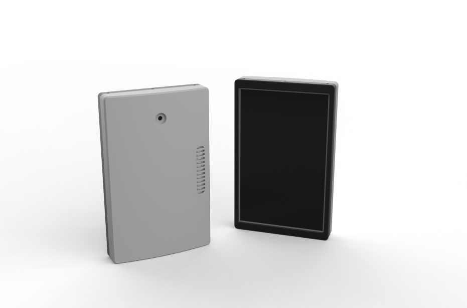
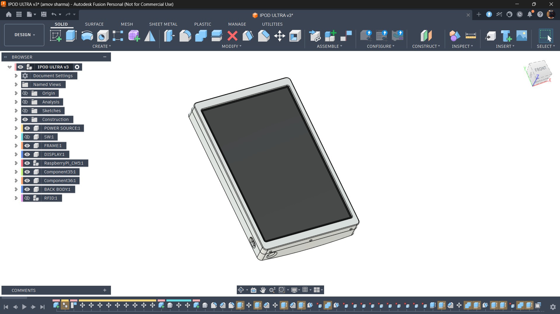
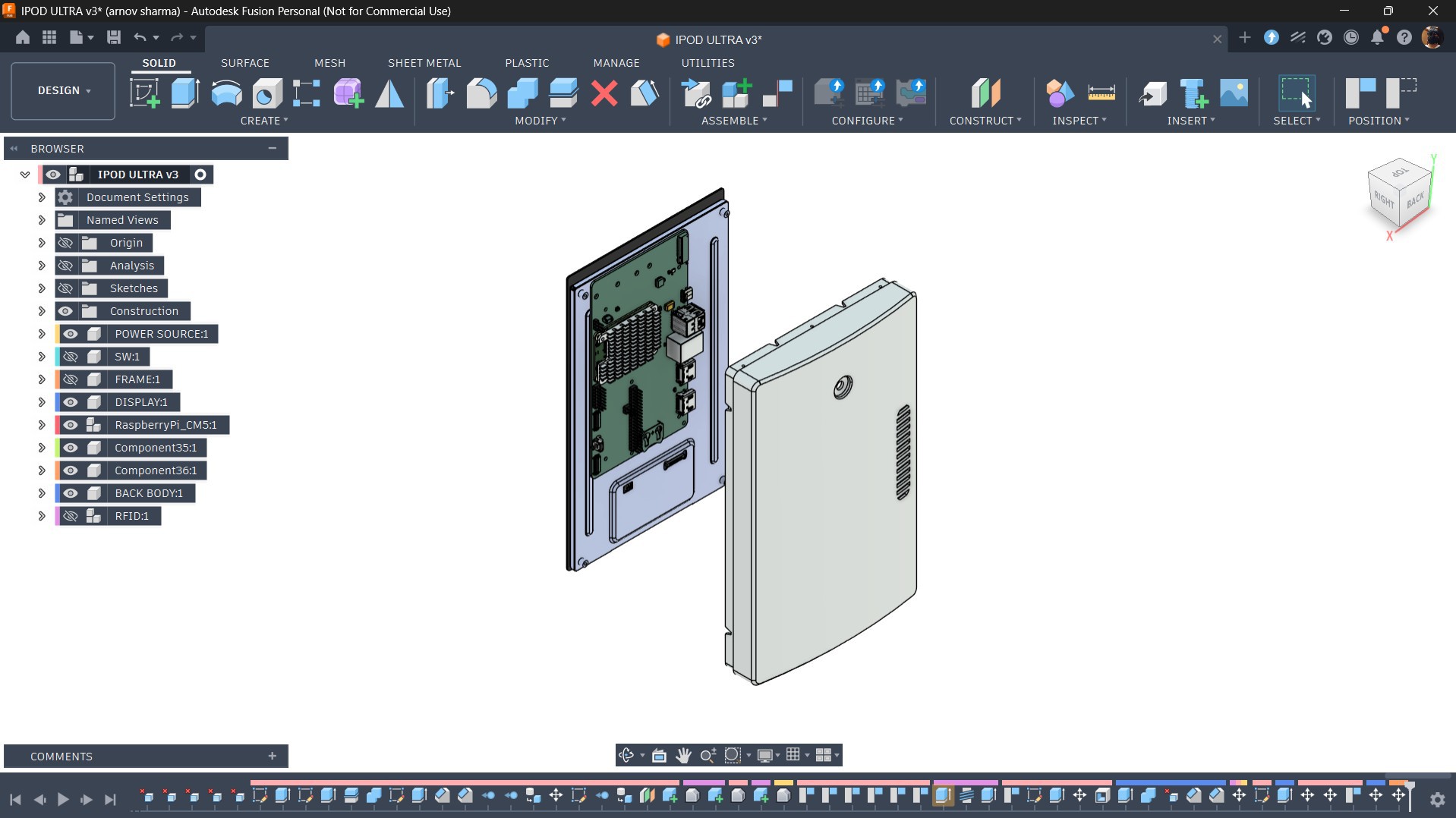
The main design of iBrick follows a simple, boxy form with a slightly curved back enclosure. The overall construction is divided into two primary parts: the front frame and the back enclosure, with the internal hardware, including the display, Raspberry Pi Compute Module 5, power bank, battery, and other electronics, remaining largely unchanged from the original Absolute Linux Tablet.
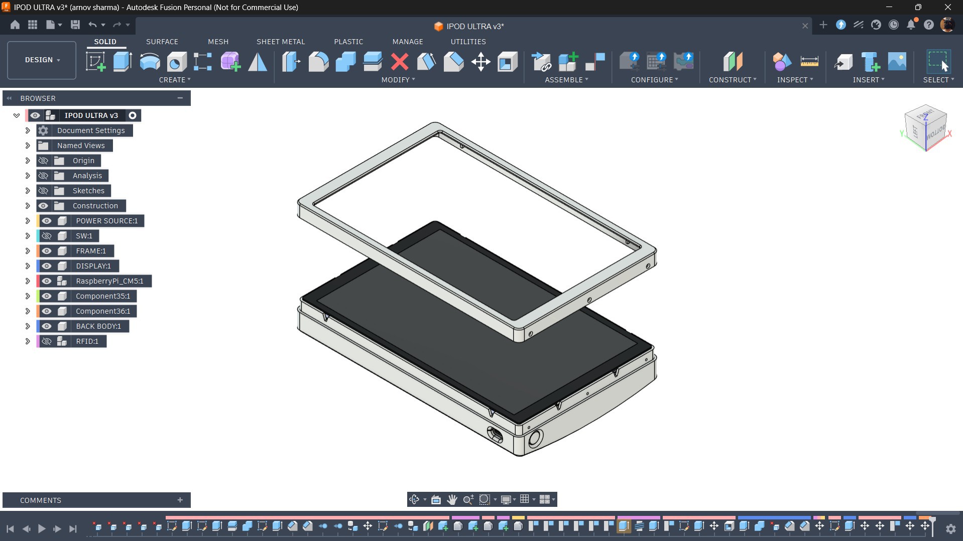
The main redesign was focused on the back enclosure. I intentionally kept it chunky and oversized, giving iBrick its distinctive brick-like appearance, which also inspired the name. The front frame uses a minimal-bezel design to maximize the display area while keeping the overall look clean.
Rather than trying to physically replicate every detail of the original iPod Nano, my goal was to keep the hardware design simple and recreate the recognizable iPod experience primarily through the software UI. Elements such as the classic navigation, click wheel, menus, and animations were therefore implemented digitally, allowing the oversized enclosure to remain simple while the software provides the nostalgic iPod character.
5
CONSTRUCTION
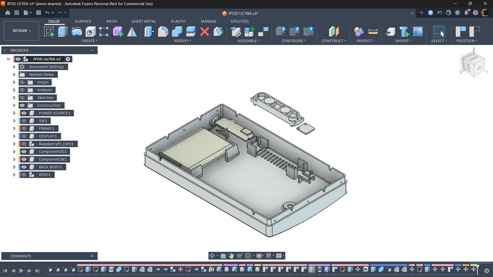
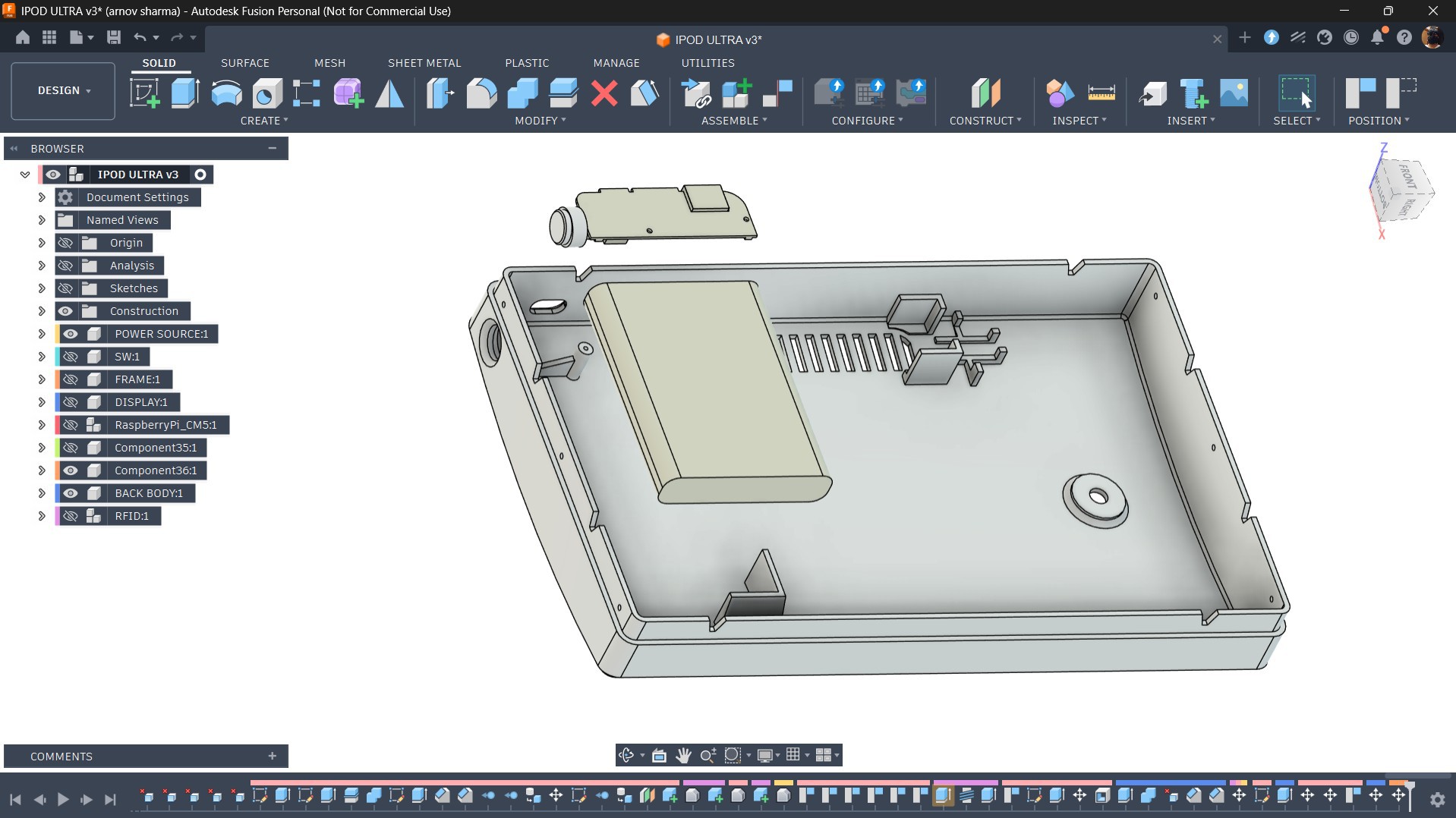
The enclosure mainly consists of two parts: the front frame, which holds the display and Raspberry Pi CM5 assembly in place, and the back enclosure, which houses the battery pack and power circuitry. Both parts are designed to fit together and are secured using M2 screws inserted through mounting holes positioned around the perimeter of the frame.
The back enclosure also includes dedicated mounting features for the speaker and MAX98357A I2S amplifier, allowing both components to be securely positioned inside the enclosure.
Similarly, the lithium-polymer battery has a designated area where it can be secured in place, while the power circuit sits on two dedicated mounting bosses and is fastened using M2 screws. This keeps the internal components organized and prevents them from moving around inside the enclosure.
6
3D PRINTED PARTS
After finishing the model, we exported three parts: the back part, the frame, and the button actuator.
The frame part and button actuator were both printed in Black Hype PLA with a 0.2 mm layer height and 25% infill. The enclosure was printed in Grey Hype PLA with similar settings.
7
DISPLAY & CM5 ASSEMBLY
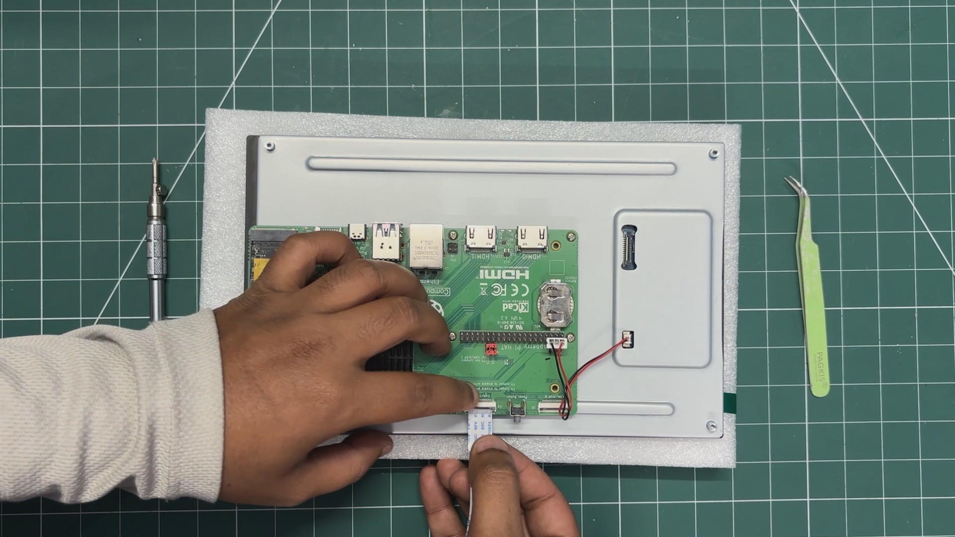
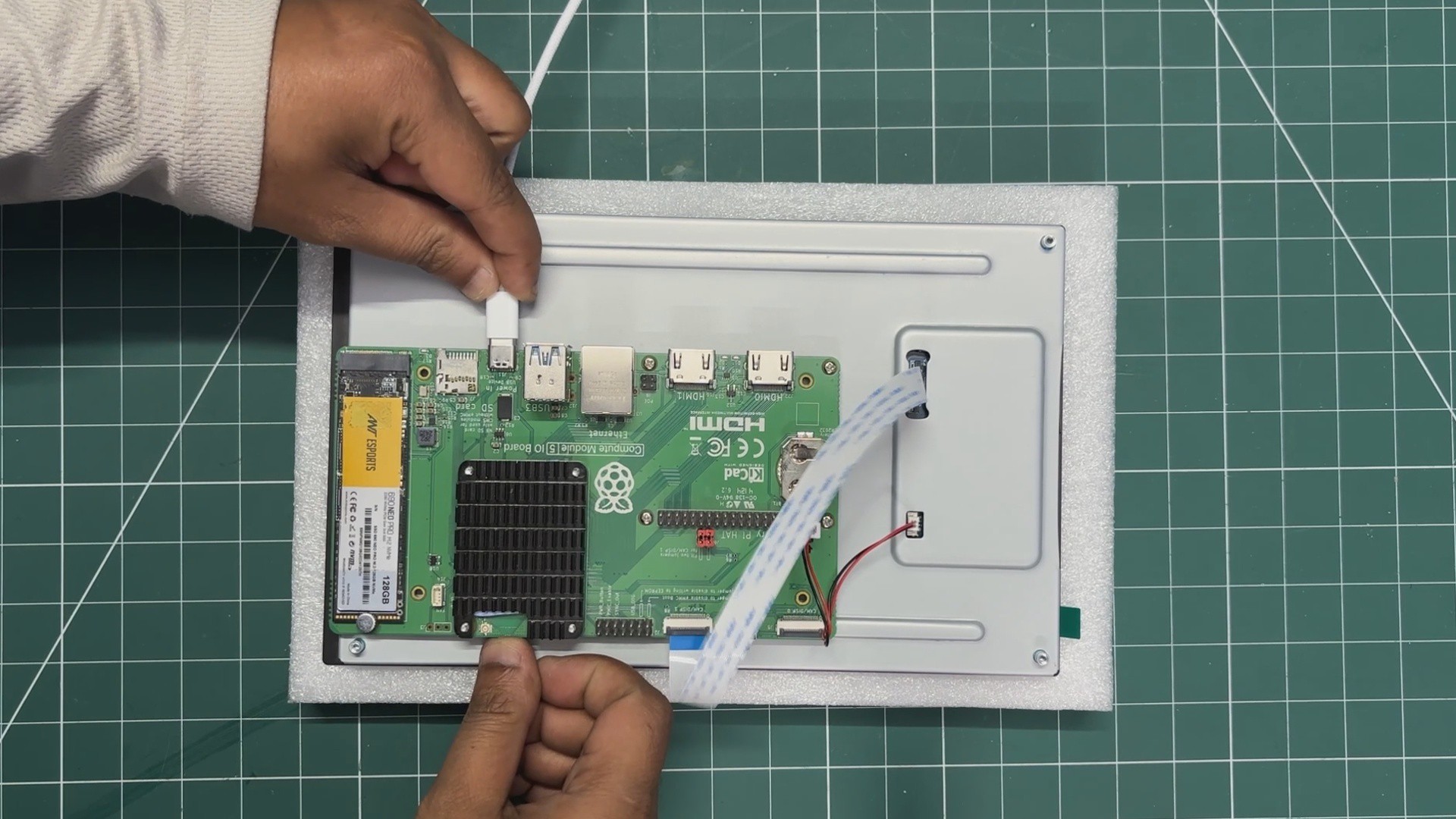
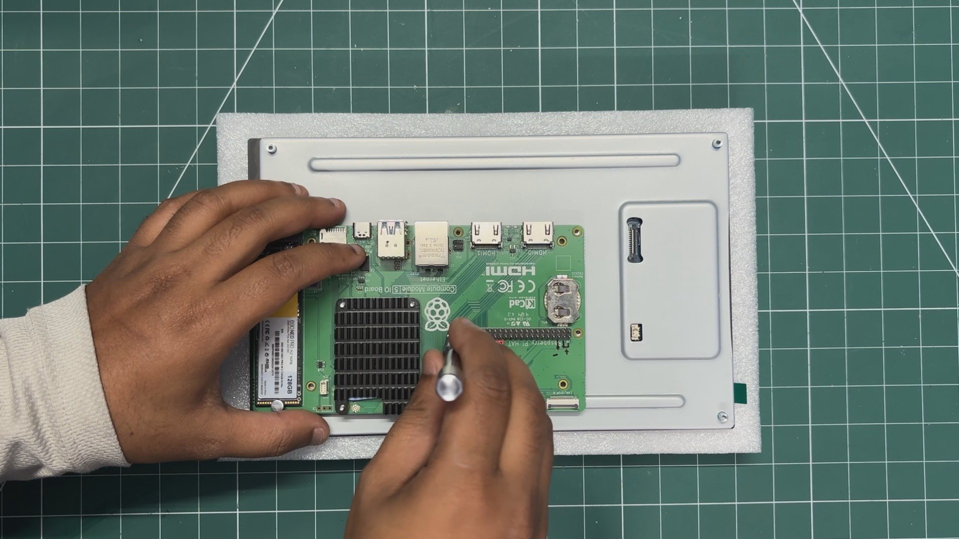
We begin the display and CM5 assembly process by positioning the expansion board over the back of the display.
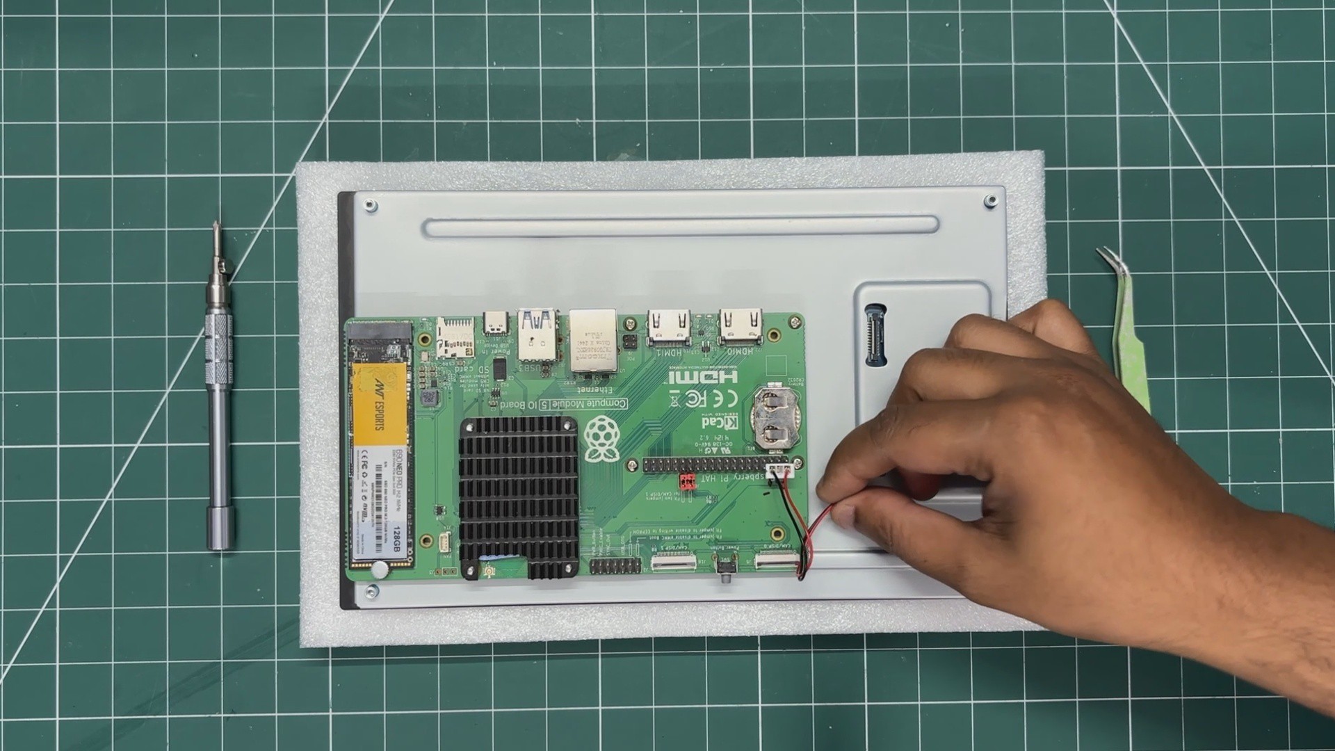
We align the mounting holes of the display with the Raspberry Pi board and then use the provided four M2.5 bolts to secure both of them together.
Next, we connect the power wire harness. One side is connected to the JST connector on the display, while the other end goes to the Raspberry Pi's GPIO header. We connected 5V to 5V and GND to GND. Basically, the display will be powered directly from the GPIO header of the Raspberry Pi.
8
CONFIG FILE EDIT
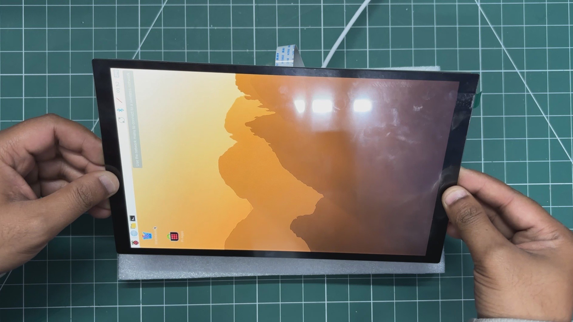
We plugged in the power and were hoping this would be a plug-and-play job, but things are never that simple, and the display didn't work straight away.
We needed to connect an external monitor to our CM5, open a terminal, and then edit the config.txt file.
We added the following line at the bottom of the file.
On the wiki page for this display, to Waveshare's credit, they did include a custom pre-flashed Raspberry Pi OS Trixie image. If we use that image and flash our Raspberry Pi with it, the display boots up without requiring any manual edits to the configuration files.
9
CM5 & MAX98357A ASSEMBLY
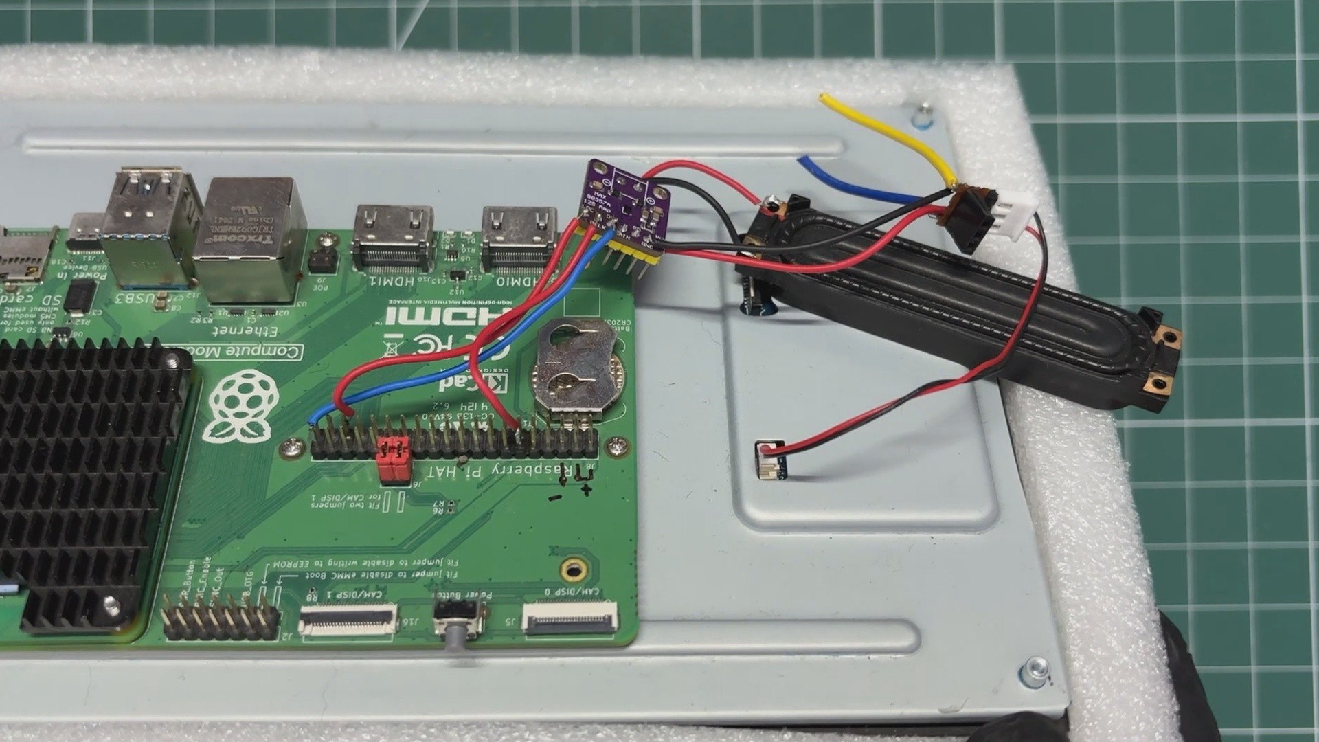
Now comes the assembly process for the MAX98357A I2S amplifier and Raspberry Pi CM5.
We start by connecting the 5V and GND pins of the CM5 to the VCC and GND pins of the MAX98357A.
Next, we connect the BCLK pin of the MAX98357A to GPIO18 on the CM5 GPIO header, followed by connecting LRC to GPIO19 and DIN to GPIO21.
Finally, we connect the speaker's positive and negative terminals to the Speaker positive and negative outputs on the MAX98357A amplifier, completing the audio connection between the CM5 and the speaker.
10
FRAME & CM5-DISPLAY ASSEMBLY
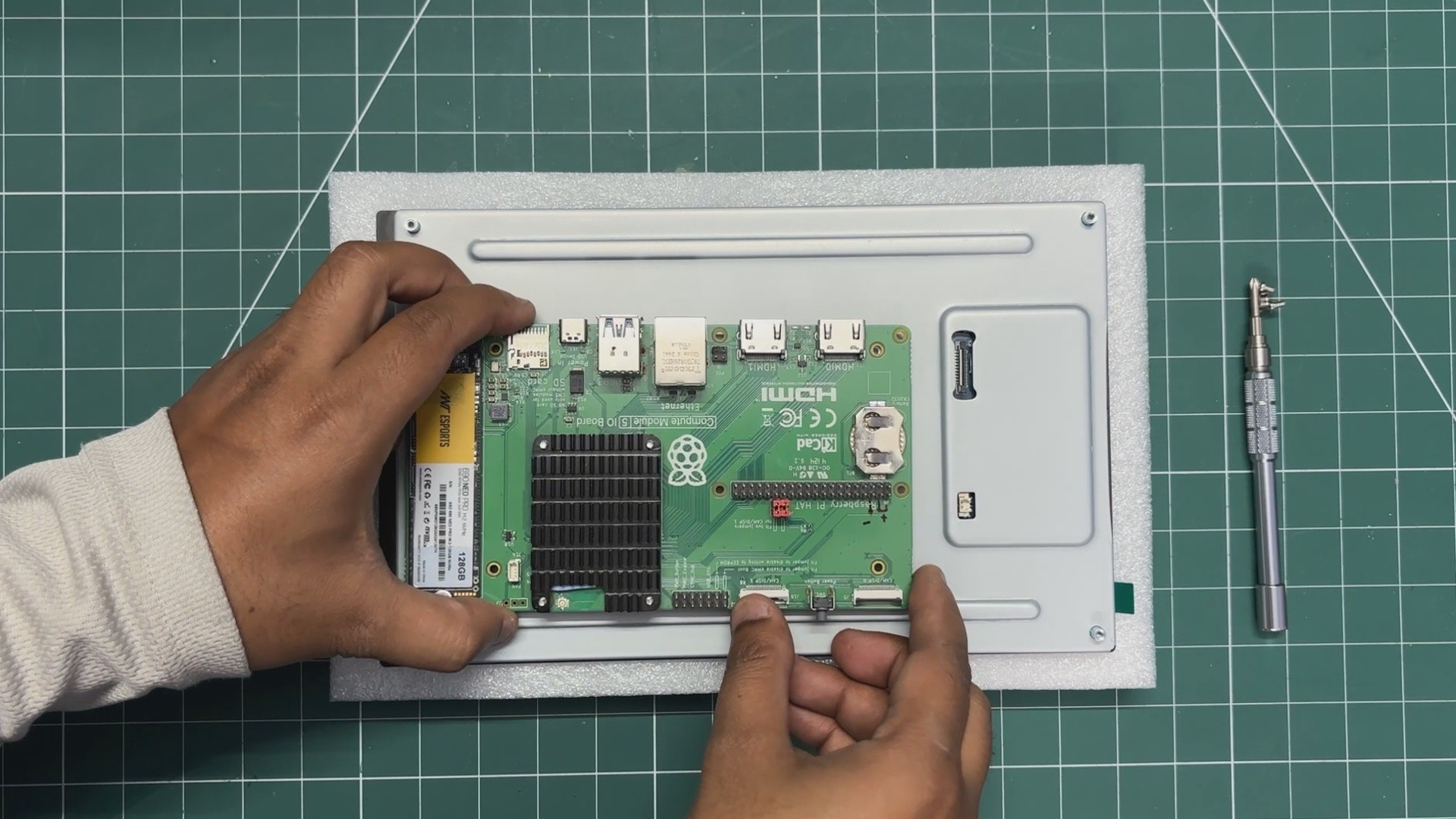
The display is now placed into the frame, making sure it sits properly in position.
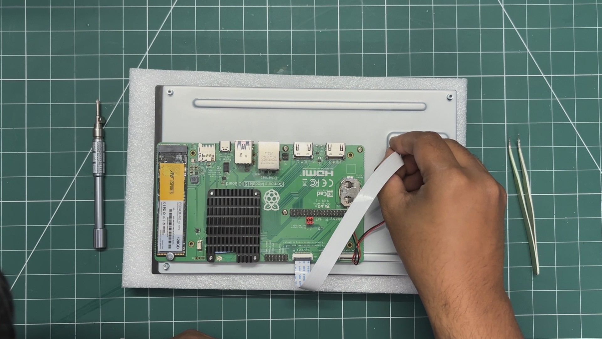
We then reconnect the CM5's DSI connector to the display's DSI connector for video and touch communication.
Finally, we connect the display's power input to the 5V and GND pins on the CM5, providing the required power to the screen.
 Arnov Sharma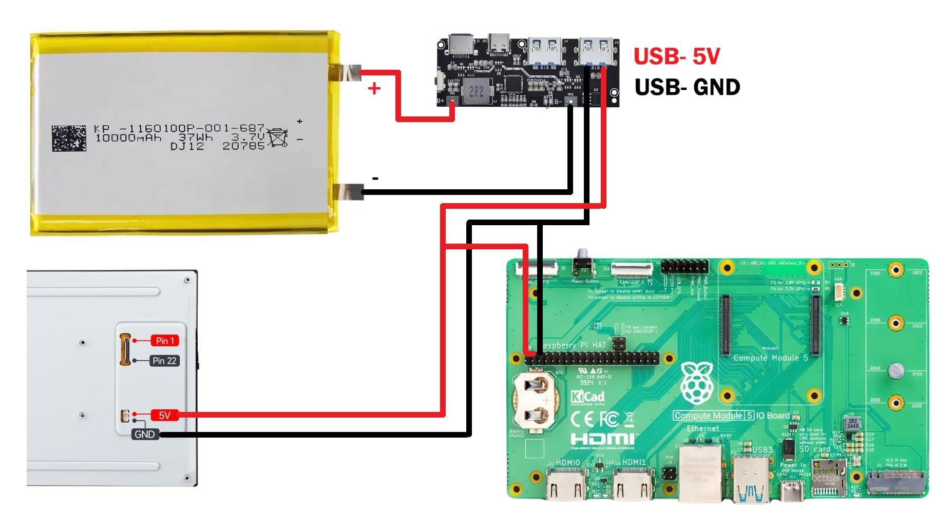
Discussions
Become a Hackaday.io Member
Create an account to leave a comment. Already have an account? Log In.