Electronic load is a useful piece of laboratory equipment for testing of power supplies, batteries, solar cells and other sources of electricity. The original motivation for MightyWatt was the testing of PEM fuel cell.
The core of MightyWatt R3 is a special FET designed for linear applications from IXYS, such as IXTH64N10L2 or IXTH75N10L2. The important is the "L2" which indicate linear applications. Normal FETs do not work well in linear mode. Google "Spirito effect" to learn more.
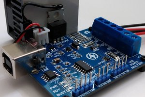
The heat sinking is provided by a 5V 50mm fan with a BGA-style heatsink. Underneath the FET is a small, 0402-footprint thermistor, that is used for monitoring the temperature.
How does it work
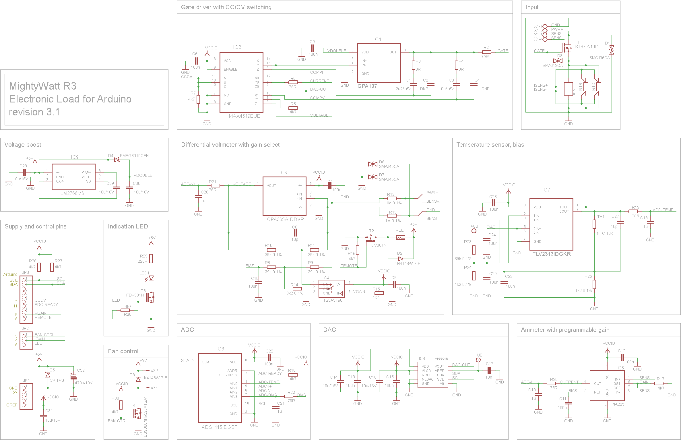
MightyWatt R3 (MWR3) works internally in constant current or constant voltage mode. Other modes, such as constant power or constant resistance, can be maintained in a software feedback loop in the firmware. MWR3 is an Arduino shield so the logic is contained in the Arduino's processor.
The selected value of current or voltage is recalculated to DAC value and sent over I2C. The DAC is then fed to the gate driver – an op-amp that maintains the selected constant value. Its feedback is taken from either the ammeter or voltmeter, depending on the selected mode.
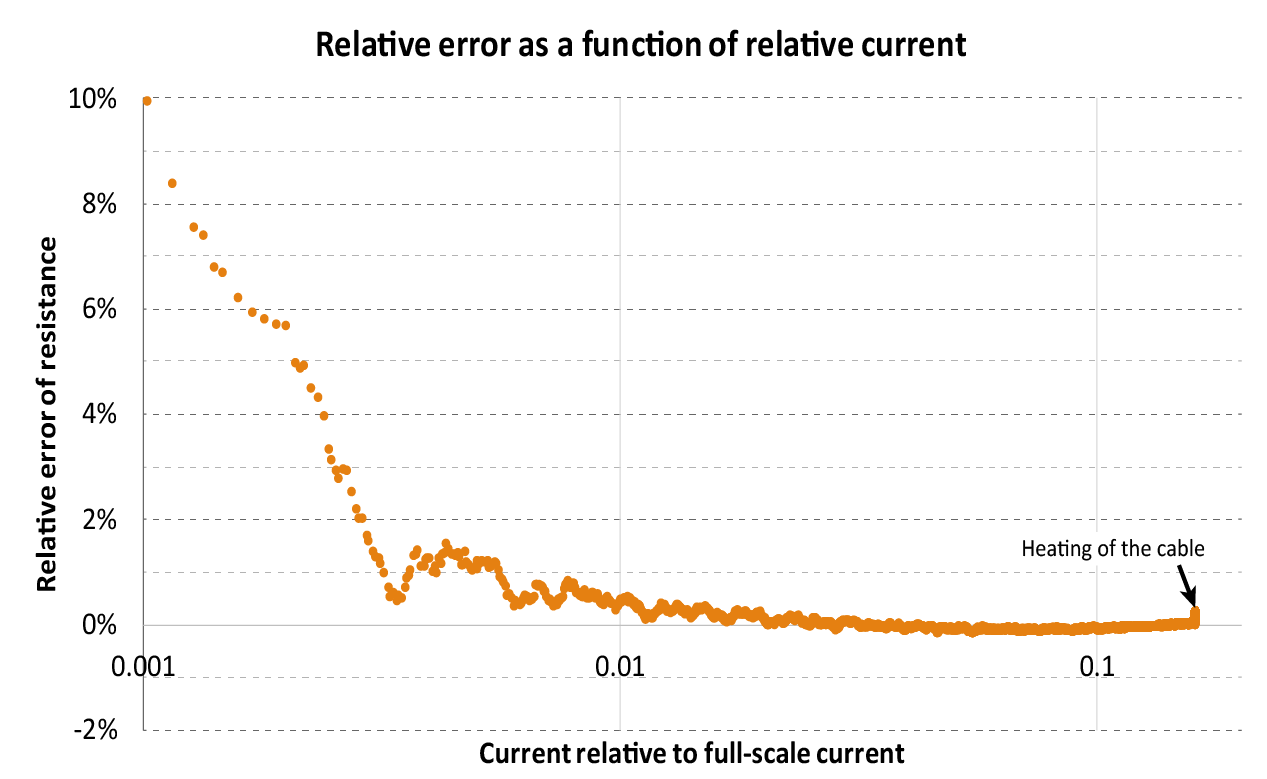
Voltmeter and ammeter have both two ranges to make measurements more precise. Ammeter second range is 8 times below the main range. Voltmeter ranges can be set to practically anything up to 60 V. It is a safety limit, the electronics can withstand more so in an enclosure, you can go higher.
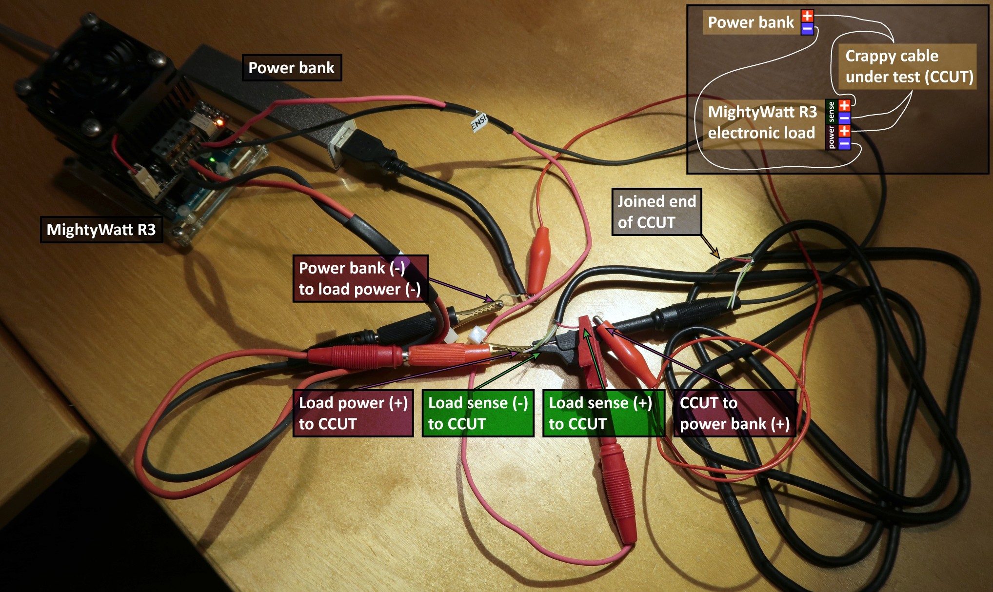
Voltmeter is differential and it can sense voltages that have offset from the voltages at the power terminals. This is very useful for 4-terminal voltage sensing. MWR3 has 4 terminals – two for power and two for the voltmeter. In this way, it is possible to exclude cable resistance from the measurement. But it can also measure at the power terminals. A relay switches between these two voltmeter modes.
There is a proper protection with 5 TVS diodes (5V line, power line, FET gate and 2× voltmeter). There are only thin-film 0.1% resistors in the differential voltmeter, there is temperature measurement and voltage boost for FET gate driver so the main transistor can be fully open. Both the voltmeter and ammeter have bias for great linearity near zero. There is a LED which can be programmed to indicate stuff like flowing current, higher temperature or anything else. Fan can be automatically switched off for light loads.
Software
I have made a Windows program (in C#) for controlling MightyWatt R3.
It has full manual control, you can also create scripts for running custom test protocols, you can log data, display statistics and integrated values (charge, energy) and if you install gnuplot, it can show real-time charts.
Do you want to build one? Do you like this project? Be sure to let me know!


 Sagar 001
 Alex Fatiuk
 Lithium ION
 Stefan Wagner