-
Using MightyWatt R3 to measure crappy chinese cable resistance
12/19/2017 at 20:27 • 0 commentsWhat is in this test (Introduction)
In this log, I will share my experience with testing of power handling capability of a really cheap USB cable using MightyWatt R3. How cheap? I don't know because I found this cable in my box of USB cables. I probably got this bundled with some device. What you will find inside this test? A (not so) shocking revelation that chinese manufacturers are able to make a cable with virtually no copper at all.
I wasn't really going to test the cable in the first place. I was actually going to test a cheap powerbank I got as a corporate gift. You know, one of those small powerbanks that have a single 18650 cell inside and a boost converter ending in a USB port. And for testing, I needed a cable I could connect to MightyWatt R3. So I cut the cable, saving only the USB-A connector end with a few centimetres of cable. Inside, I found four tiny conductors that had barely any metal in them.
How I tested the cable (Experimental part)
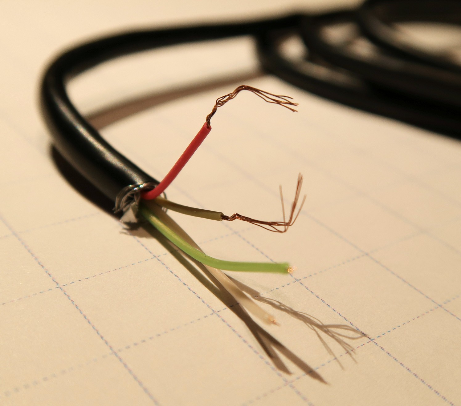
The USB-B connector was cut from the remaining part of the cable, which was subsequently used for the experiment. The length of the cable for experiment was measured using a tape measure. Both ends of the crappy cable under test (CCUT) were stripped and the foil and braided shielding was removed (Figure 1). Using the removed part with the USB-A connector, the power conductors were identified to be red (VBUS) and grey (GND). These conductors were stripped to bare copper and twisted together at one end, forming a single conductor.
![Figure 1 Figure 1]()
Figure 1: Crappy USB cable and its internal conductors. Red wire – VBUS, gray wire – GND. Green and white wire – differential data pair. A power bank was used as the power supply. A MightyWatt R3 electronic load (24A/3A, 30V/5.5V ranges) was used as the measurement device.
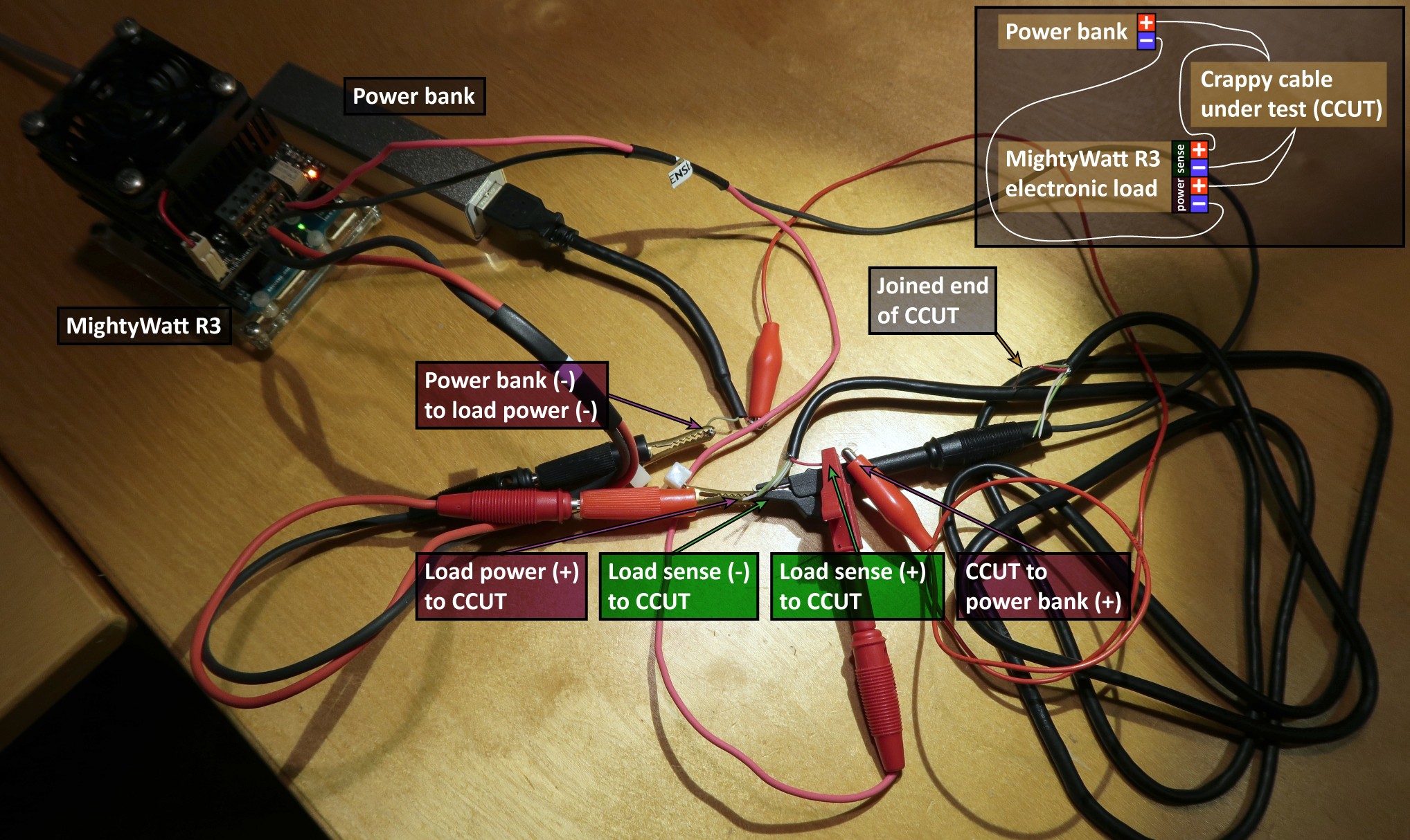
The positive terminal of the power bank was connected to one end of CCUT, the negative terminal was connected to negative (PWR-) terminal of the load. The other end of CCUT was connected to positive (PWR+) terminal of the load. The voltage-measuring (sense) terminals of the load were connected at the ends of CCUT to measure the voltage drop across it (Figure 2).
![Figure 2 Figure 2]()
Figure 2: Measurement setup showing MightyWatt R3 electronic load, power bank and CCUT A 30-second linear sweep from 0 to 0.5 A was applied by the load followed by 60-second constant current at 0.5 A. Voltage drop across CCUT was measured as well as the applied current. The resistance was calculated as a ratio of voltage drop and applied current at the beginning of the 60-second constant current phase. The ambient temperature was 22 °C. Approximate cable gauge was estimated from the experimental data using a table on Wikipedia.
So how bad was it? (Results and discussion)
Pretty bad…
The total resistance was 3.7 Ω and slowly increasing as the cable was heating up. The length of the cable was 1.55 m so back and forth 3.10 m. That means the specific resistance was a solid 1.19 Ω/m, which is horrible. The wire gauge was approximately 36 AWG and its cross-section around 0.0127 mm2, which can be safely rounded to zero :-) If you really put 0.5 A through this cable, you would get 1.85 V drop, which would probably cause any device supplied from that cable not working.
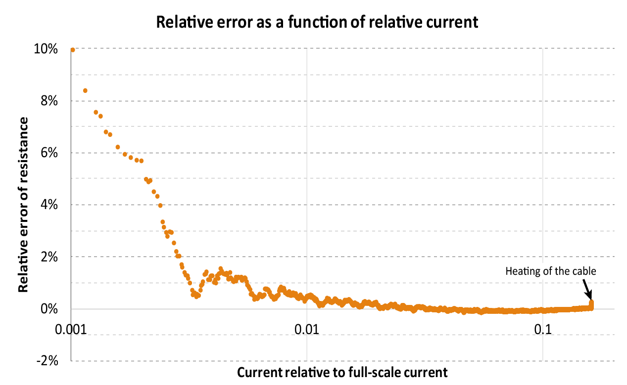
On the bright side, MightyWatt R3 turned out to be great at such an experiment. The accuracy within 1 % was available when the current was a meager 1/180 of the used range (Figure 3).
![Figure 3 Figure 3]()
Figure 3: Relative measurement error as a function of current range. Accuracy better than 1 % starts at approximately 1/180 of the current range. Heating causing the increased resistance is visible as the vertical slope at the right end of the curve. The bottom line (Conclusions)
Crappy cables are crappy. And at the USB 2.0 maximum current may be totally unusable.
May this be a cautionary tale and also an inspiration how to use an electronic load to measure stuff!
-
Autoranging and constant power/resistance using CV
04/07/2017 at 22:09 • 0 commentsTwo new features to MightyWatt R3 and some observations:
- First, it is possible to disable autoranging. This may be useful to get rid of glitches when switching ranges. When a range is switched, a few millisecond long dip can form before the load stabilizes. Disabling autoranging can prevent this. The logic is this: When in CC mode, the current range autoranging can be disabled while the voltmeter autoranges as usual. And vice versa.
- Another feature concerns constant power (CP) and constant resistance (CR). Typically, these software modes are internally constant current but in some cases, it might be better to use constant voltage internally. This is now possible. But I recommend using internal CC mode for normal operation.
The observations:
- 3 A CC mode, the current noise/ripple is 0.75 mA RMS in 20 Hz to 300 kHz band.
- Temperature coefficient for current measured at 10 A, 70 W was about 18 ppm/K.
- Slew rate measured as the time taking to get from 10 % to 90 % is about 19000 A/s when going from 0 to 20 A.
-
Comparison of Arduino Uno and Arduino Zero
03/31/2017 at 22:36 • 0 commentsI was getting asked how does the Uno perform against Zero with MightyWatt R3.
Measurement rate
After fixing a watchdog reset flaw, I am now able to compare the performance of those two boards. This comparison was made using firmware version 3.0.2.
The venerable Arduino Uno uses 8-bit AVR from Atmel (well, Microchip…) – ATmega328P running at 16 MHz.
Arduino Zero (M0/M0Pro) has a 32-bit ARM Cortex M0+, SAMD21, from the same company, running at 48 MHz, i.e. three times faster.
How does it influence MightyWatt R3?
First of all, let me tell you that the ADC is precise but not terribly fast. In its 16-bit version (ADS1115), it does approximately 860 samples per second, meaning that it is not possible to get more than 430 complete measurements (current + voltage) per second. Plus, there is a communication overhead on the I2C bus and all the calculations the program must do in every pass of the main program loop. So, in the end, Arduino Uno makes about 220 measurements per second and 4350 main program loops. Arduino Zero finishes 237 measurements per second and 12500 main program loops. The measurement is thus about 8 % faster with Zero and there are 2.9 loops per every loop on Uno. This number is very close to the ratio of core clocks of the two Arduinos, which is 3. What was a little bit surprising for me is that a 32-bit ARM Cortex M0+ does not seem to have any additional advantage against an 8-bit AVR core besides the core clock speed. At least not in this application.
Accuracy
But what about the analog accuracy? In theory, it shouldn't be dependent on Arduino because the ADC and DAC are all part of the MightyWatt R3. However, Uno runs at 5 V and Zero at 3.3 V and while both the ADC and DAC as well as the rest of the analog circuitry has an excellent power supply rejection, it might have an impact. Let's see the numbers:
A calibration performed on Zero was uploaded to both Uno and Zero. A constant-voltage mode was used and a power supply limited to 1 A. Then, 20 V was set on the same MightyWatt R3, once using Uno and once using Zero as the control board.
With Zero, MightyWatt R3 reported 19.998 V while the multimeter (Keysight 34461A) measured 20.0036 V.
With Uno, MightyWatt R3 reported 20.000 V while the multimeter (Keysight 34461A) measured 20.0042 V.
The relative error of the set voltage was 0.018 % (Zero) and 0.021 % (Uno).
The relative error of the measured voltage was 0.028 % (Zero) and 0.021 % (Uno).
The relative difference of Uno vs. Zero was 0.003 % for the setting of voltage and 0.007 % for the measurement of voltage.
Because the difference of Uno vs. Zero is very small, the calibration can be used interchangeably between those two control boards.
-
Found and fixed a bug in sketch for Arduino Zero
03/31/2017 at 21:55 • 2 commentsI have just found and fixed a nasty bug that was slowing down main program loop when using Arduino Zero.
The problem was in the watchdog system. If you don't have experience with processor watchdog, I'll make a short intro: A watchdog is a countdown timer that once it reaches zero causes a processor reset. That means you have to periodically reset the counter so it never reaches zero. And periodically resetting means calling it in some kind of a loop. If this loop freezes, the watchdog timer will eventually reach zero and reset the processor, which is what it is supposed to do – an automatic reset when your program freezes or enters an infinite loop.
A watchdog can use a dedicated oscillator. In the case of Arduino Zero and my sketch, it is the ultra-low power internal oscillator running at 32.768 kHz. And because it is very slow, any write to a system that uses it – such as the reset of the watchdog timer – needs a synchronization with the main CPU clock, which runs at 48 MHz on Arduino Zero.
I was wrongly assuming this synchronization was fast, whereas it was not, governed by the speed of the slower clock. My code made a blocking wait for this synchronization:
WDT->CLEAR.reg = WDT_CLEAR_CLEAR_KEY; /* reset watchdog timer */
while(WDT->STATUS.bit.SYNCBUSY){} /* wait for sync */
A stupid mistake that was, fortunately, easy to find and fix to a non-blocking call:
if(WDT->STATUS.bit.SYNCBUSY == false) /* synchronization is not busy, meaning it is synchronized */
{
WDT->CLEAR.reg = WDT_CLEAR_CLEAR_KEY; /* reset watchdog timer */
}
This call will only reset timer if the previous reset was already synchronized. There. Fixed.
The performance gain? Tremendous. Previously, I was getting around 100 measurements per second and 400 turnarounds of the main loop, now I am at 237 measurements per second with 12500 (!) main loops per second.
So today's lesson is clear: Don't make blocking calls if you don't have to.
-
Update to 220 reports per second and external power resistor watchdog
03/30/2017 at 22:17 • 0 comments- Just updated the ADC measurement logic so that temperature is measured only about twice per second. That means voltage and current can be measured more frequently. The increase of measurement (V+I) rate is from 140 measurements per second to 220! This is equal to the report rate to computer and hence the maximum log rate in the control program.
- When you have an external series resistance, such as a power resistor, to add some extra watts to the power handling, the windows control program now lets you type in the power resistor rating. The program can then automatically stop the load when the external power resistor rating is exceeded (thank you Jyrki for suggesting this!).
MightyWatt R3: 70W Electronic Load for Arduino
MightyWatt R3 is a programmable electronic load made as an Arduino shield


