 Ashwin K Whitchurch
-
1Step 1
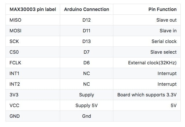
We used the ProtoCentral Single-lead ECG monitor breakout board based on the MAX30003 single-channel AFE chip from Maxim Integrated to acquire ECG using two electrodes connected to the chest. This board is connected to an Arduino Uno using a standard SPI interface. Connections are made as given in the following table:
![MAX30003 breakout board connections]()
MAX30003 breakout board connections
-
2Step 2
Unlike the traditional 3-electrode system which requires a driven right leg (DRL) electrode for common mode rejection, the MAX30003 is very unique in the fact that it works off of 2 electrodes only, making it easier to use.
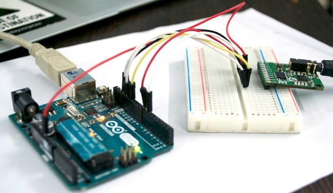
![ProtoCentral MAX30003 board connection to an Arduino Uno]()
ProtoCentral MAX30003 board connection to an Arduino Uno
The Arduino sketch for use with this hookup reads the real-time ECG and R-to-R interval data from the MAX30003 over SPI, puts it in a data packet and sends it over the Uno's USB-UART interface. This Arduino sketch is available in the links at the end of this article.
-
3Step 3
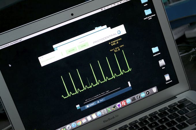
We also made a GUI with processing that takes this data from the serial port and plots the data in real-time with also the R-to-R interval time (in milliseconds) and the instantaneous heart rate *based on the current R-R value.
The R-to-R interval displayed here is the time between the last detected R peak and the previously detected R peak to get an instantaneous value of the R-R interval as well as heart rate. The instantaneous heart rate would be different from the regular heart-rate(if you would use a medical monitor) in the fact that generally heart-rate is calculated from a window of 5-10 secs of stored ECG data, rather that taking the immediate time.
![GUI for displaying the real-time data]()
Single-lead ECG & heartrate variability monitor
In this project we show how we made a single-lead ECG monitor for heart-rate variability using the MAX30003 and an Arduino Uno.
Discussions
Become a Hackaday.io Member
Create an account to leave a comment. Already have an account? Log In.