 youkito1991
-
1DIY Soft Start & Speed Control for Angle Grinder
An angle grinder can jerk suddenly when it is switched on directly from the AC mains. This sudden start can be uncomfortable and may create a safety risk for the user. The PCB of this project from JLCPCB
In this project, I designed a compact Soft Start and Speed Control circuit for an angle grinder.
The circuit has two main functions:
- Soft Start: Limits the high starting current and allows the motor to start more smoothly.
- Speed Control: Allows the motor speed to be adjusted using a potentiometer.
The circuit uses two 120-ohm, 5-watt resistors for the Soft Start function and a 12-volt DPDT relay to bypass the resistors after approximately 2 seconds.
For speed control, a BTA41 TRIAC is used to control the AC power supplied to the motor.
The PCB is compact and can be adapted for other motor-driven power tools such as drills and cutting machines.
Let's build it!
-
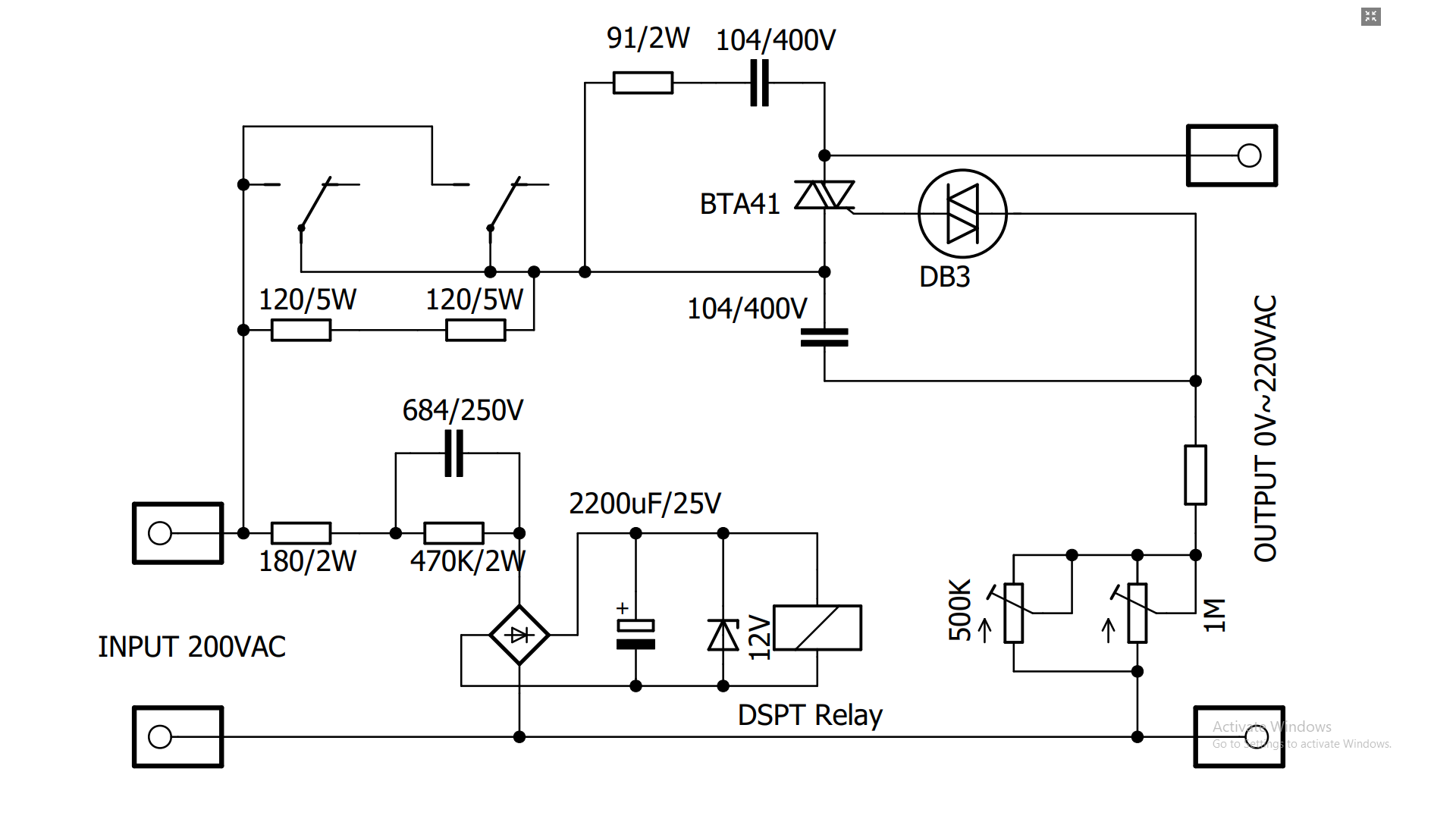
2The Schematic
The circuit consists of two main sections: the Soft Start and Speed Control circuits.
The Soft Start section uses two 120-ohm, 5-watt resistors to limit the starting current.
When the grinder is switched on, the motor initially receives power through these resistors. After approximately 2 seconds, the relay activates and connects the motor directly to the AC mains.
The Speed Control section uses a BTA41 TRIAC to adjust the motor speed.
![]()
-
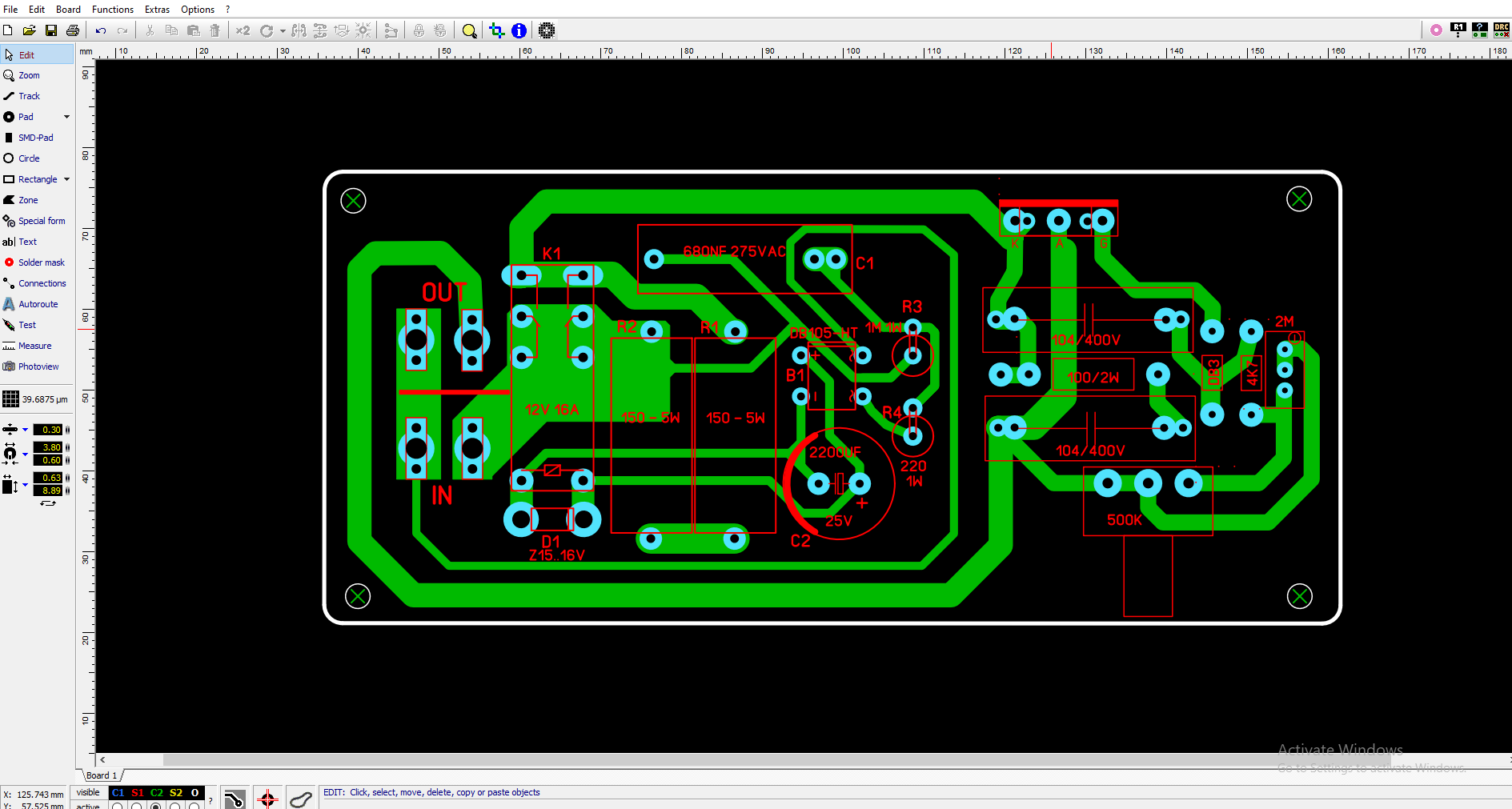
3PCB Design
After completing the schematic, I designed a compact PCB to fit all the components into a small space.
The PCB contains the Soft Start circuit, relay, power supply section, TRIAC Speed Control, and adjustment potentiometers.
The goal was to keep the board as compact as possible while maintaining enough space between the high-voltage sections.
![]()
-
4PCB Manufacturing
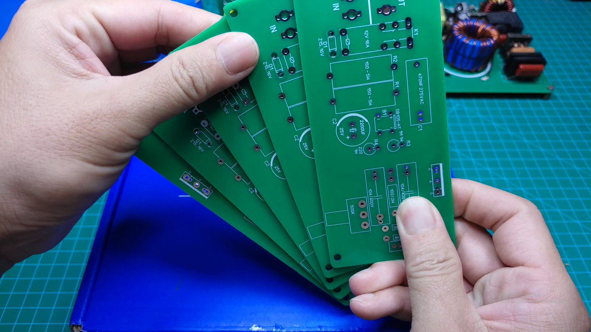
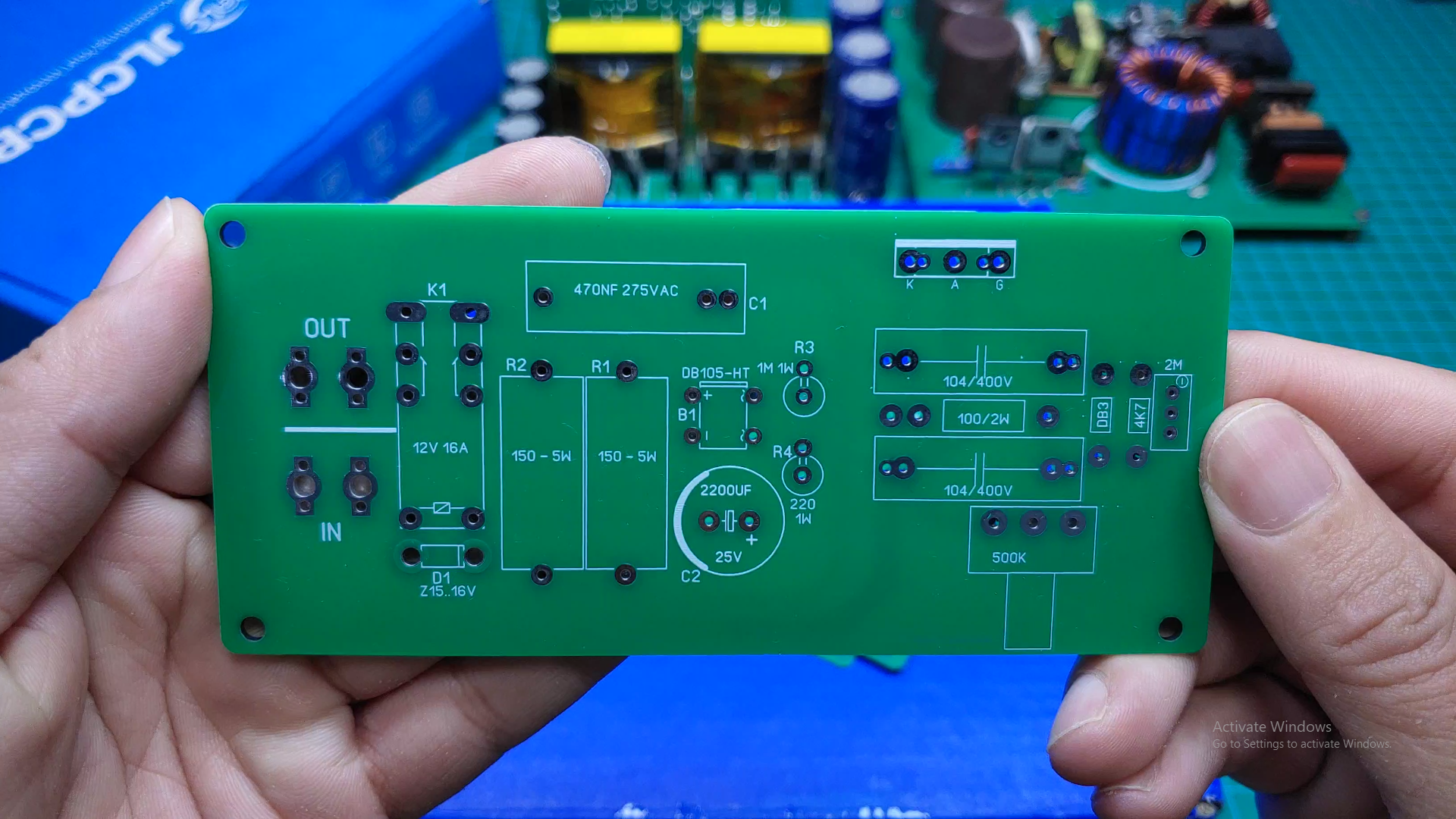
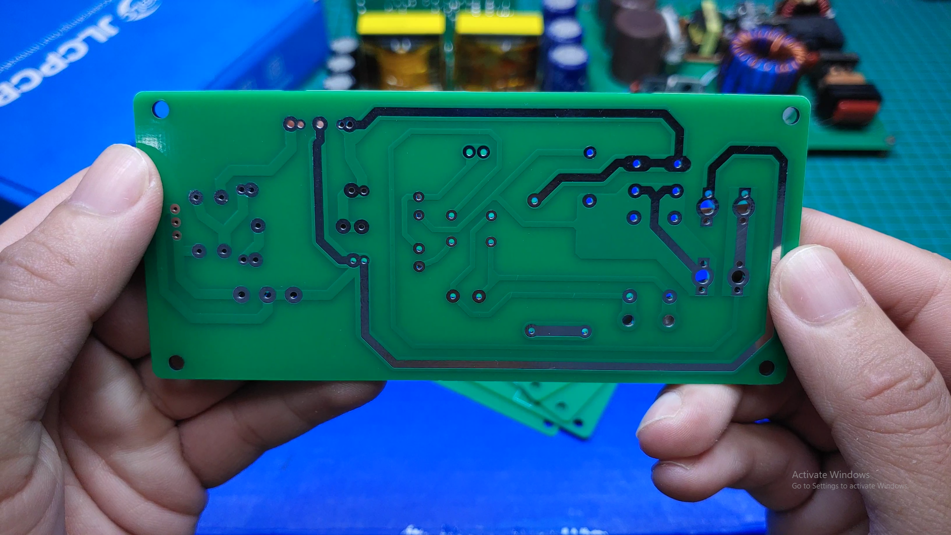
After completing the PCB design, I uploaded the Gerber files to JLCPCB.
The finished boards arrived in about one week.
I was very impressed with the PCB quality. The traces were clean and precise, the silkscreen was sharp and clear, and the overall finish looked very professional.
The compact PCB makes the circuit easy to integrate into a power tool.
![]()
![]()
![]()
-
5Components
The components used in this project are common and easy to find.
Main components include:
- 2 × 120-ohm, 5-watt power resistors
- 1 × 12-volt DPDT relay
- 1 × BTA41 TRIAC
- 1 × 2,200-microfarad, 25-volt capacitor
- Potentiometers for speed and minimum voltage adjustment
- Diodes and other passive components
- PCB
The relay power supply is derived from the 220-volt AC input through a capacitive dropper circuit.
-
6Assemble the Soft Start Circuit
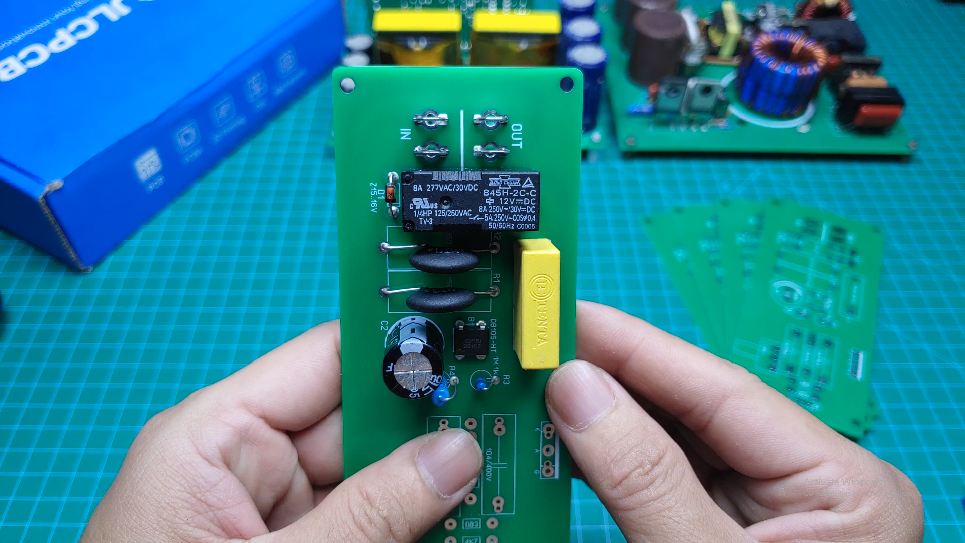
I started by assembling the Soft Start section.
The two 120-ohm, 5-watt resistors are connected in the motor power path.
When the grinder is turned on, these resistors limit the initial current and reduce the sudden mechanical jerk.
The relay is used to bypass the resistors after the startup period.
![]()
-
7Assemble the Speed Control Circuit
Next, I assembled the Speed Control section.
The main power switching component is the BTA41 TRIAC, which is suitable for controlling high-power AC motors.
A potentiometer is used to adjust the motor speed.
There is also a small potentiometer on the PCB for adjusting the minimum output voltage.
![]()
-
8Testing the Soft Start & the Speed Control
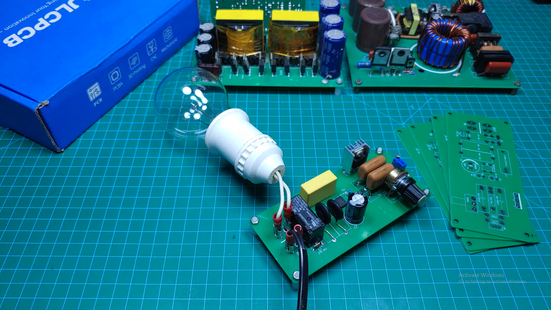
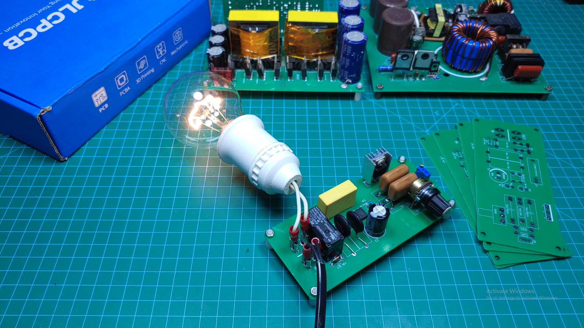
After assembling the Soft Start section, I powered the circuit and tested its operation.
When 220-volt AC power is applied, the 2,200-microfarad capacitor begins charging.
As the control voltage rises, the relay activates after approximately 2 seconds.
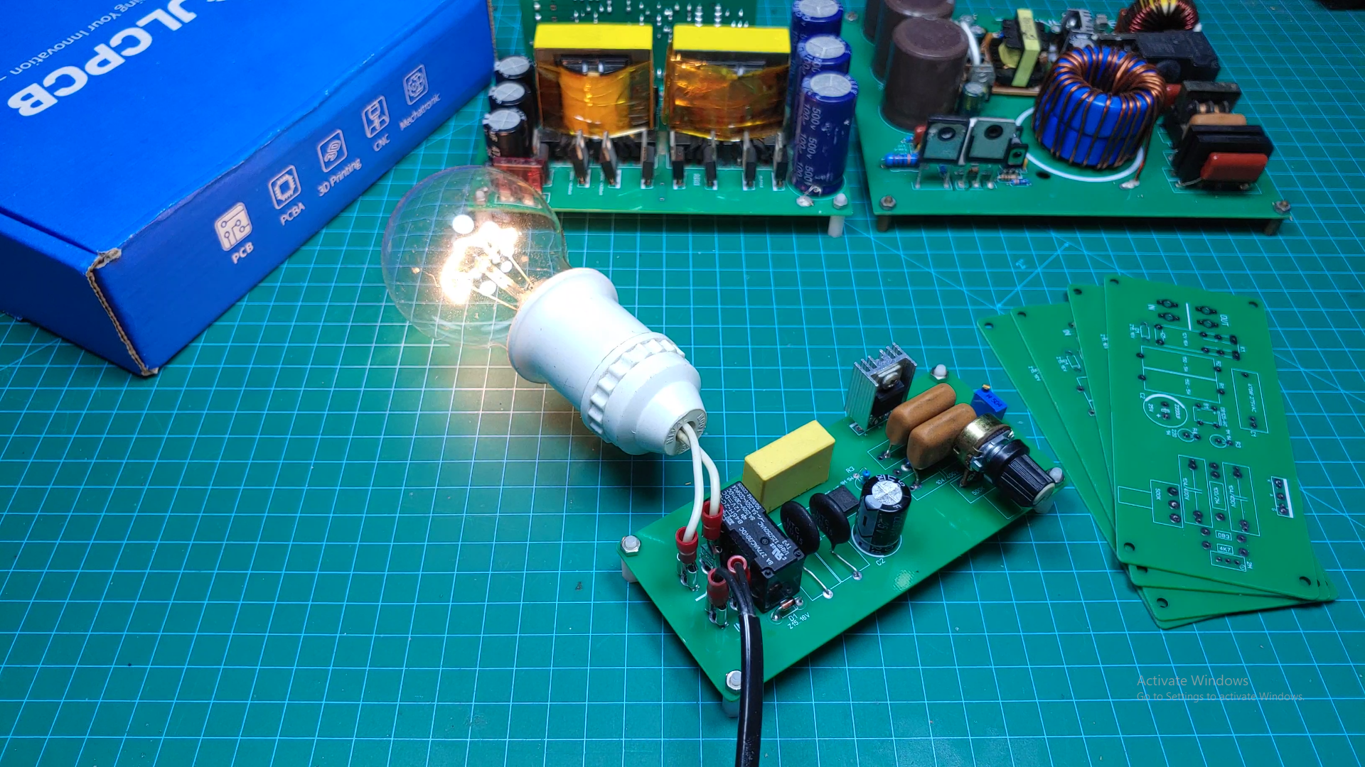
During startup, the motor receives power through the current-limiting resistors. After the relay closes, the resistors are bypassed and the motor is connected directly to the AC supply.
This provides a much smoother startup.
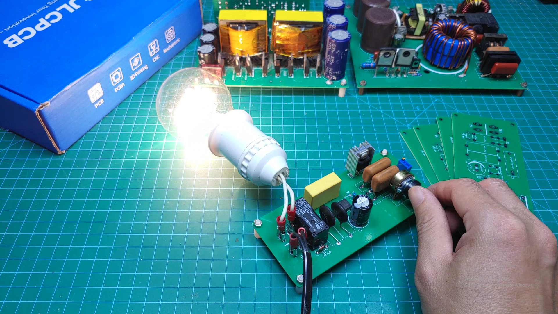
I tested the Speed Control circuit.
The output voltage can be adjusted using the main potentiometer.
The small potentiometer on the PCB controls the minimum output voltage when the main control is turned to its lowest position.
In my test, I initially set the minimum output voltage to approximately 145 volts and then increased it slightly.
![]()
![]()
![]()
![]()
-
9Final Result
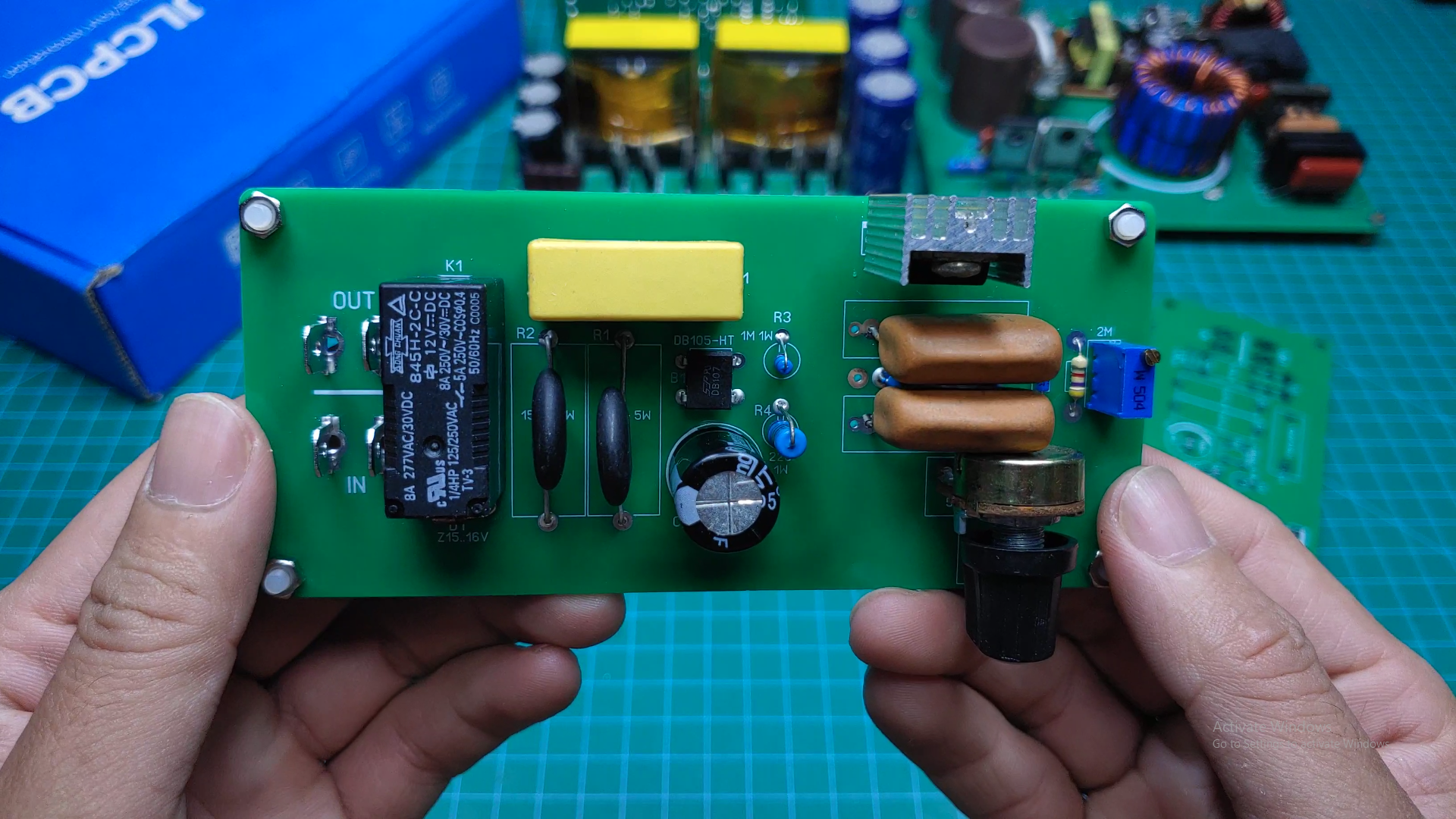
After installing all the components, the completed circuit is very compact.
The Soft Start function prevents the grinder from starting with a sudden jerk, while the Speed Control allows the motor speed to be adjusted according to the application.
This circuit can be used not only with angle grinders, but also with drills, cutting machines, and other suitable motor-driven power tools.
By reducing the high starting current and mechanical stress during startup, the circuit may also help reduce stress on the motor and contribute to longer equipment life.
I also made a video showing the complete design, PCB assembly, and testing process.
WARNING: This project works directly with 220-volt AC mains voltage.
Mains voltage can cause serious injury or death.
Do not touch the circuit while it is powered. Use proper insulation, fusing, grounding, enclosure, and safe measurement equipment.
Only build and test this circuit if you have sufficient experience working with mains-voltage electronics.
Always disconnect the power before modifying or handling the circuit.
This project combines two useful functions into one compact PCB: Soft Start and Speed Control.
The Soft Start reduces the sudden startup current and mechanical jerk, while the TRIAC-based Speed Control allows the motor speed to be adjusted.
I hope this project gives you some ideas for your own power-tool controller.
Thanks for reading, and don't forget to check out the video!
Soft Start & Speed Control for Angle Grinder
Limits the high starting current and allows the motor to start more smoothly.Allows the motor speed to be adjusted using a potentiometer.
Discussions
Become a Hackaday.io Member
Create an account to leave a comment. Already have an account? Log In.