Close
0%
0%

Selectric-256

What if E2E encrypted chat was a hardware peripheral?

Similar projects worth following
What if E2E encrypted chat was implemented as a hardware peripheral?

What if we rolled-in WiFi, so that the end-user device has no Internet connection of it's own? It's hard to trust endpoint security these days, and we've all go old computers we can re-use.

What if we used MQTT for communication, so that there are already multiple compatible public servers around the globe, but you could also trivially host your own?

The total cost to build this project is ~8 USD per device. The only required component is an ESP32S. The ESP32S3 Supermini is what I used.

I've designed an optional serial communications board, so that the device can be used with older computers. You now have post-quantum, E2E encrypted chat on your PDP-11 (punched cards not included).

You'll need to write a driver, I provide two examples.

Status: Mostly functioning. Waiting for boards from the factory. Won't be any photos until then!

What?

Objectives:

  1. Implement E2E encrypted chat over MQTT using AES-256 GCM.
  2. Implement ephemeral key exchange & compute a shared secret with ML-KEM
  3. Each device is paired to another, on boot they will find each other & exchange keys with HMAC-like authentication.
  4. Runs on an ESP32 (S or S3) as a peripheral to a computer that has no Internet connection of its own
  5. Should have basic protection against message replay
  6. Should a serial+USB peripheral, so that it may be used with computers both ancient and modern. This means it will need an (optional) PCB that adds a real serial port.

Features:

  1. Plug it in to a device that doesn't have Internet access. Now it can connect to WiFi, but only for the purposes of engaging in E2E encrypted chat with exactly one other device. No other connectivity is permitted. The device doesn't even know how to engage in other connectivity.
  2. This simplifies endpoint security. Since it's only allowed & capable of doing one thing, and that one thing is completely on public channels, it's pretty easy to detect if it's doing anything else.
  3. By implementing chat over public MQTT servers, there's no single central provider.
  4. It is intended to be controlled by a software application that provides a UI etc. suitable for the host device.

There's no TLS support presently. I may add it later, but overall the device doesn't rely on trusting the broker.

Why?

I was quite ill recently, and in my fever-dreams I recalled a device: The IBM Selectric-251, a fictional typewriter from a sci-fi television show called Fringe.

The nature of my madness mandates that I create the devices that claw their way out of my dreams. Also, my C++ is not very good, and this was an opportunity to work on it a bit. As such, I didn't see much point of using AI to write any code, all hallucinations are entirely my own (re: fever-dreams).

In the television show, two "quantum-entangled" typewriters function such that what you type in one comes out the other, regardless of where they are and without the possibility of the message being intercepted.

Since the device from the television show functions via magical "quantum-entanglement", and real-life quantum entanglement doesn't work that way, we'll need to "entangle" them via some other method. So instead I use two arrays of 32 bytes generated by:

tr -dc A-Za-z0-9 </dev/urandom | head -c 32; echo

One array identifies the local device, the other array identifies the remote device. These are never used for encryption, because then an attacker that obtains one of the devices could decrypt all prior communications.

So instead, these identifiers are used to:

  1. Compute two MQTT channels, optionally with a user-specified modifier like the first 7 digits of the Unix timestamp
  2. Authenticate (with something HMAC-like) a handshake that performs ML-KEM key exchange

The computed channels have two purposes:

  1. To obfuscate traffic analysis if the user wishes to do so.
  2. Prevent message replay. An attacker could replay an old connection, which would not let them impersonate you or decrypt your messages, but would make it difficult to connect up the two devices.

Once the key exchange is complete, the devices have an ephemeral shared secret suitable for performing AES-GCM. For simplicity, GCM is used to authenticate all future messages. I added a session message counter (encrypted along with the plaintext) to prevent message replay.

This design offers several advantages over the fictional Selectric 251:

  1. It exists
  2. It uses 256 bit encryption, which is 5 bits more than 251 (I presume that's what the '251' indicates)
  3. It's compatible with more than just electric typewriters
  4. It's better than quantum, it's post-quantum!

A weakness of the system is that anyone possessing the 32-byte identifiers on the device can impersonate the owner (although they would also need to know your channel-hopping scheme, and they cannot decrypt prior communications). So, store your devices somewhere safe.

selectric256_gerbers.zip

Production files for the factory

Zip Archive - 49.09 kB - 09/15/2026 at 01:45

Download

selectric256.kicad_pcb

kiCAD PCB

kicad_pcb - 214.58 kB - 09/15/2026 at 01:44

Download

selectric256.kicad_sch

ugly kiCAD schematic

kicad_sch - 57.03 kB - 09/15/2026 at 01:44

Download

selectric256.kicad_pro

kiCAD project file

kicad_pro - 15.14 kB - 09/15/2026 at 01:44

Download

  • 1 × ESP32S3 SuperMini The only required component
  • 1 × Serial communications PCB Optional
  • 1 × MAX232 Optional
  • 1 × Serial port Optional
  • 5 × 0603 1uF Capacitor Optional

View all 8 components

  • In Which I Make Amusing Errors

    Legionlabs • a day ago • 0 comments

    Well, the boards had a pretty glaring error when they came in: My MAX232 chips are DIP-16, and I had defined a DIP-14 package. (KiCAD & gerbers in project source have been fixed)

    I thought that KiCAD would raise a warning for this, it turns out that's not the case! Serves me right for relying on automated checks instead of checking carefully myself. Anyway, as part of this I had searched Google for 'MAX232 DIP-14 variant', because I thought that perhaps I had designed with some other chip by accident, and could just order it.

    No such luck! Google's AI spewed out something to the effect that no such variant exists, and moreover it's impossible because (blah blah blah). Well, it underestimates what I spiteful miser I am (15$ for new boards? Bah, humbug.). So we should go ahead and prove it wrong.

    Pins 8 & 9, which don't fit in my board, are for R2IN and R2OUT, which I don't use. Optimally, one of those should be grounded, but I could live without that. So logically, I could just cut two pins off the IC. Then it would be all lopsided though, can't have that!

    The MAX232 isn't a particularly complex chip, so I reasoned even on old fab processes, the silicon die would be pretty small. It would be also very likely be positioned optimally within the chip package to save on (probably gold) bonding wire. So I could just... cut off the rest of the chip.

    Then pins 1-7 on the new chip would already be connected correctly, and pins 8-14 would need to be offset by 2 positions by cutting any connections & making new ones with bodge wires.

    That leaves the following sequence of operations for me to follow on the new chip:

    • Pin 8: No change required
    • Pin 9: Bodge wire to pin 1 of ESP32S3
    • Pin 10: Cut connection to GND around pin, then bodge wire to pin 2 of ESP32S3
    • Pin 11: Cut connection to trace, bodge wire to serial port pin 3
    • Pin 12: Cut connection to trace, bodge wire to serial port pin 2
    • Pin 13: Cut connection to trace, bodge wire to GND
    • Pin 14: Cut connection to trace, bodge wire to VCC

    This took about 20 minutes of surgery, I checked connections, powered it on, and it was fine. Before and after surgery image below for your possible amusement and edification. Pins 11,12,13 connected on verso.

  • Public Brokers Now Supported

    Legionlabs • 09/23/2026 at 02:20 • 0 comments

    I was making a silly mistake with MQTT username & password handling, which caused the device to only work correctly when these were set, preventing the use of a public MQTT broker. So, that's fixed now. 

    I tested with "broker.emqx.io" and it works fine!

  • How Key Exchange Works

    Legionlabs • 09/20/2026 at 04:34 • 0 comments

    This diagram goes over the steps in key exchange.

    NB without the use of ephemeral channels, someone could replay an old connection message. This won't let them decode your messages, but will let them prevent key exchange and generally be a nuisance. The ephemeral channels should follow the same rules as a nonce -- they don't have to be secret, but do need to be unpredictable and should not be re-used.

    The ML-KEM key exchange is quite heavy compared to ECC 25519 (800 bytes vs. 32 bytes, then the ciphertext is even bigger!). To make matters worse, I encode the bytes as hex strings, doubling that already large size! We have enough memory to handle it, and for now this makes it easier for me to validate communications (e.g. because I can copy-paste them, decode, and validate). However I should eventually fix this so that I just send raw bytes over MQTT.

  • How communications are initiated

    Legionlabs • 09/17/2026 at 02:01 • 0 comments

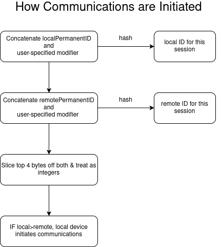
    This possibly helpful chart shows how communications are initiated between two devices. I'll make more for the various other functions of the device.

    Important things to note:

    1. If there's no user-specified identifier, the channel will be static. So at least the server operator (possibly others, depends on MQTT server settings) can determine how many unique devices have contacted each other.
    2. They can also determine how many times, and when, specific devices have contacted each other.
    3. If someone obtains your device, they could determine which sessions were yours.

    It is possible to mitigate these using simple schemes:

    1. Using the first 7 digits of the Unix timestamp would mitigate the first two.
    2. Choosing a random string at the end of communications to use for the next chat mitigates all 3.
    3. If you don't care about preventing traffic analysis, you can use a static value.

  • First Working Version

    Legionlabs • 09/14/2026 at 02:17 • 0 comments

    I've been working on this a couple of weekends, and so far it seems to work reasonably well:

    1. The devices connect up reasonably OK.

    2. The chat works

    However, if you don't turn on the devices in the right order, and the one that initiates communication is turned on too early, they can "miss" each other. So I added a command to retry communications.

    1. In the case where the device in question is not expected to initiate communications, the command does nothing.

    2. In the case where the device in question is expected to initiate communications, it tries again.


    I've also added a status LED that lights up when the devices have exchanged keys, and dropped the serial communications speed to 9600 baud for compatibility. The device doesn't transmit that much data, so this should be plenty fast enough. I've also added support for the RGB LED on the ESP32S3 SuperMini to show connection status:

    • Red: Config not received yet OR error state
    • Yellow: Config received, waiting for connect
    • Green: connected, ready to chat

    Later, I should also add a command that returns the same information via serial command, so I can add a loop to the driver, something simple like:

    If not connected --> try to reconnect once in a while. Or I could use MQTT LWT.

View all 5 project logs

  • 1
    Choose a device

    I have checked that this project is compatible with the ESP32S3 and ESP32S. I recommend the ESP32S3 SuperMini, it's small and works well. Don't accidentally buy the ESP32C3 version, that one won't work.

    With some difficulty, this firmware can work on the RP2040 as well -- but you will need to modify it, along with several of the underlying libraries, to make it work.

  • 2
    Fetch, prepare, and flash the firmware

    The firmware is available here.

    The file you need is selectric256.ino. You will need to update the permanent IDs on the device.

    The permanent IDs are what lets the devices automatically connect to each other, and are just 32 random bytes. You can generate them using:

    tr -dc A-Za-z0-9 </dev/urandom | head -c 32; echo

    For two devices to automatically connect, the local ID of one device needs to be the remote ID of the other. So the two devices have them swapped.

    Once that's done, you can flash the firmware using the Arduino IDE. For the ESP32S3 Supermini, set the board as 'Ozobot DRVKit' (I thought ESP32S3 Dev Board would work, but it didn't for me). For ESP32S, Set it to ESP32 DevModule. You should also set Tools-->Pin numbering-->Legacy.

    Finally, if not using an ESP32S3 SuperMini, you must comment out this line:

    #define superMini

  • 3
    Write a driver

    The driver does three things:

    1. It sends the configuration to the device during startup.

    2. It sends serial commands to the device to control its operation.

    3. It receives notifications from the device, such as when a new message is available.

    Two example drivers in Python are provided. One is synchronous, the other is asynchronous. The async one is written by AI (given the protocol and previous driver as input), I wanted to make sure anyone who wants to use AI could one-shot it. 

View all 3 instructions

Enjoy this project?

Share

Discussions

Similar Projects

Does this project spark your interest?

Become a member to follow this project and never miss any updates