Legionlabs
-
In Which I Make Amusing Errors
a day ago • 0 commentsWell, the boards had a pretty glaring error when they came in: My MAX232 chips are DIP-16, and I had defined a DIP-14 package. (KiCAD & gerbers in project source have been fixed)
I thought that KiCAD would raise a warning for this, it turns out that's not the case! Serves me right for relying on automated checks instead of checking carefully myself. Anyway, as part of this I had searched Google for 'MAX232 DIP-14 variant', because I thought that perhaps I had designed with some other chip by accident, and could just order it.
No such luck! Google's AI spewed out something to the effect that no such variant exists, and moreover it's impossible because (blah blah blah). Well, it underestimates what I spiteful miser I am (15$ for new boards? Bah, humbug.). So we should go ahead and prove it wrong.
Pins 8 & 9, which don't fit in my board, are for R2IN and R2OUT, which I don't use. Optimally, one of those should be grounded, but I could live without that. So logically, I could just cut two pins off the IC. Then it would be all lopsided though, can't have that!
The MAX232 isn't a particularly complex chip, so I reasoned even on old fab processes, the silicon die would be pretty small. It would be also very likely be positioned optimally within the chip package to save on (probably gold) bonding wire. So I could just... cut off the rest of the chip.
Then pins 1-7 on the new chip would already be connected correctly, and pins 8-14 would need to be offset by 2 positions by cutting any connections & making new ones with bodge wires.
That leaves the following sequence of operations for me to follow on the new chip:
- Pin 8: No change required
- Pin 9: Bodge wire to pin 1 of ESP32S3
- Pin 10: Cut connection to GND around pin, then bodge wire to pin 2 of ESP32S3
- Pin 11: Cut connection to trace, bodge wire to serial port pin 3
- Pin 12: Cut connection to trace, bodge wire to serial port pin 2
- Pin 13: Cut connection to trace, bodge wire to GND
- Pin 14: Cut connection to trace, bodge wire to VCC
This took about 20 minutes of surgery, I checked connections, powered it on, and it was fine. Before and after surgery image below for your possible amusement and edification. Pins 11,12,13 connected on verso.
![]()
-
Public Brokers Now Supported
09/23/2026 at 02:20 • 0 commentsI was making a silly mistake with MQTT username & password handling, which caused the device to only work correctly when these were set, preventing the use of a public MQTT broker. So, that's fixed now.
I tested with "broker.emqx.io" and it works fine!
-
How Key Exchange Works
09/20/2026 at 04:34 • 0 commentsThis diagram goes over the steps in key exchange.
NB without the use of ephemeral channels, someone could replay an old connection message. This won't let them decode your messages, but will let them prevent key exchange and generally be a nuisance. The ephemeral channels should follow the same rules as a nonce -- they don't have to be secret, but do need to be unpredictable and should not be re-used.
The ML-KEM key exchange is quite heavy compared to ECC 25519 (800 bytes vs. 32 bytes, then the ciphertext is even bigger!). To make matters worse, I encode the bytes as hex strings, doubling that already large size! We have enough memory to handle it, and for now this makes it easier for me to validate communications (e.g. because I can copy-paste them, decode, and validate). However I should eventually fix this so that I just send raw bytes over MQTT.
![]()
-
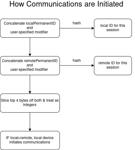
How communications are initiated
09/17/2026 at 02:01 • 0 commentsThis possibly helpful chart shows how communications are initiated between two devices. I'll make more for the various other functions of the device.
![]()
Important things to note:
- If there's no user-specified identifier, the channel will be static. So at least the server operator (possibly others, depends on MQTT server settings) can determine how many unique devices have contacted each other.
- They can also determine how many times, and when, specific devices have contacted each other.
- If someone obtains your device, they could determine which sessions were yours.
It is possible to mitigate these using simple schemes:
- Using the first 7 digits of the Unix timestamp would mitigate the first two.
- Choosing a random string at the end of communications to use for the next chat mitigates all 3.
- If you don't care about preventing traffic analysis, you can use a static value.
-
First Working Version
09/14/2026 at 02:17 • 0 commentsI've been working on this a couple of weekends, and so far it seems to work reasonably well:
1. The devices connect up reasonably OK.
2. The chat works
However, if you don't turn on the devices in the right order, and the one that initiates communication is turned on too early, they can "miss" each other. So I added a command to retry communications.
1. In the case where the device in question is not expected to initiate communications, the command does nothing.
2. In the case where the device in question is expected to initiate communications, it tries again.
I've also added a status LED that lights up when the devices have exchanged keys, and dropped the serial communications speed to 9600 baud for compatibility. The device doesn't transmit that much data, so this should be plenty fast enough. I've also added support for the RGB LED on the ESP32S3 SuperMini to show connection status:- Red: Config not received yet OR error state
- Yellow: Config received, waiting for connect
- Green: connected, ready to chat
Later, I should also add a command that returns the same information via serial command, so I can add a loop to the driver, something simple like:
If not connected --> try to reconnect once in a while. Or I could use MQTT LWT.
![]()