 Dave Doerr

System Overview
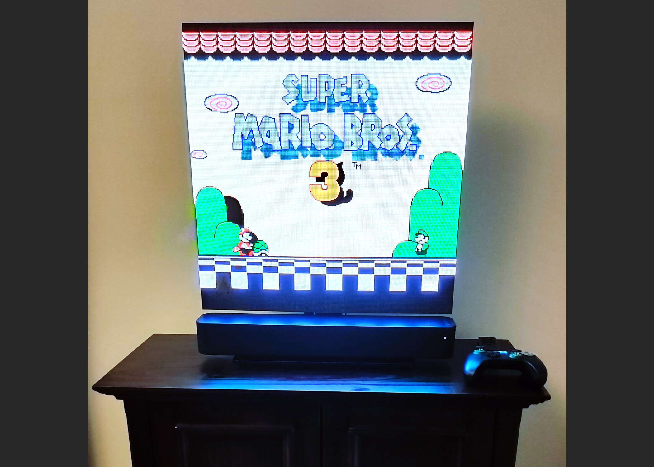
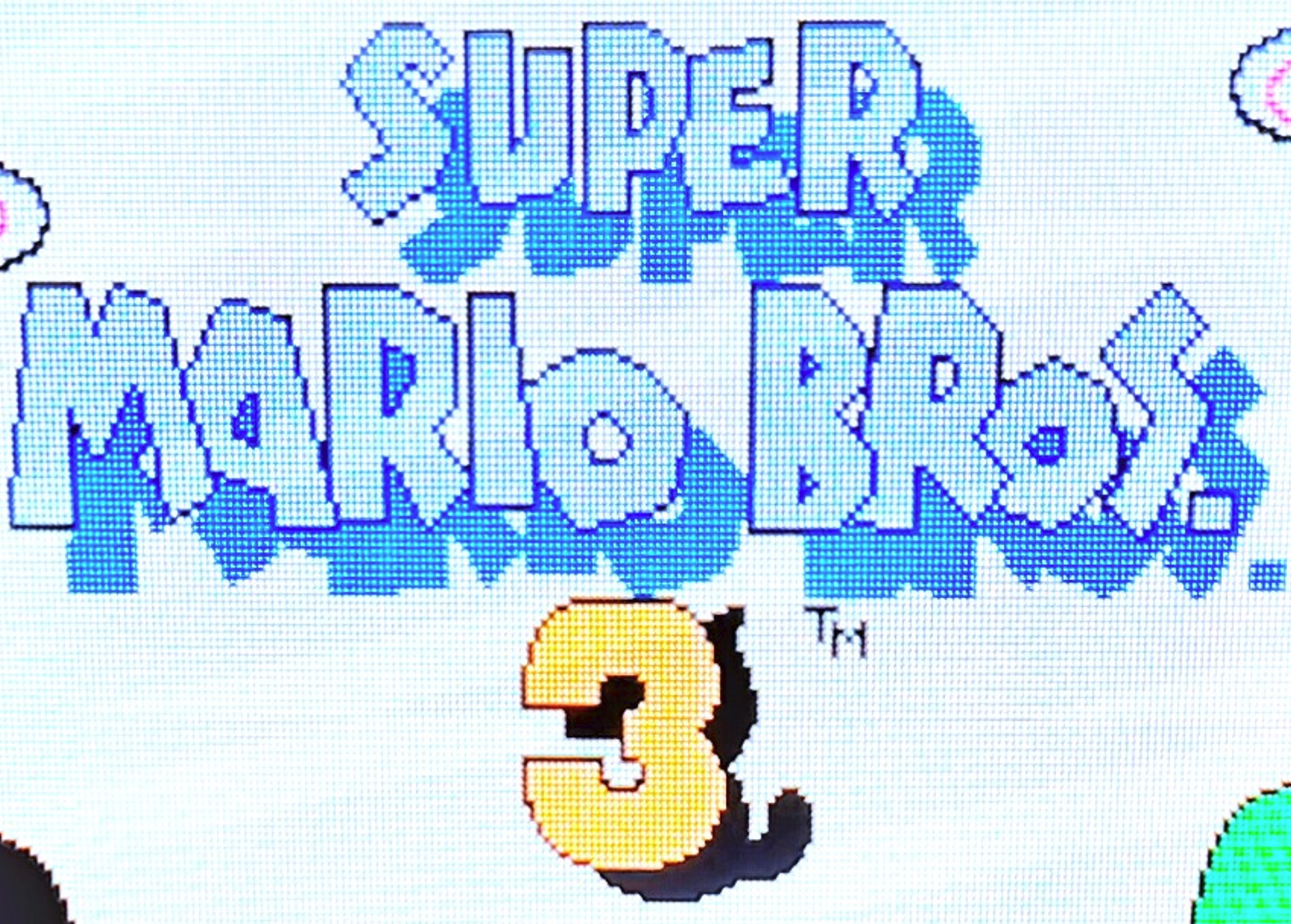
Like many LED projects, this display is much more impressive in person than in photos. The colors are vibrant, and the distinct separation between individual pixel LEDs enhances the retro look.
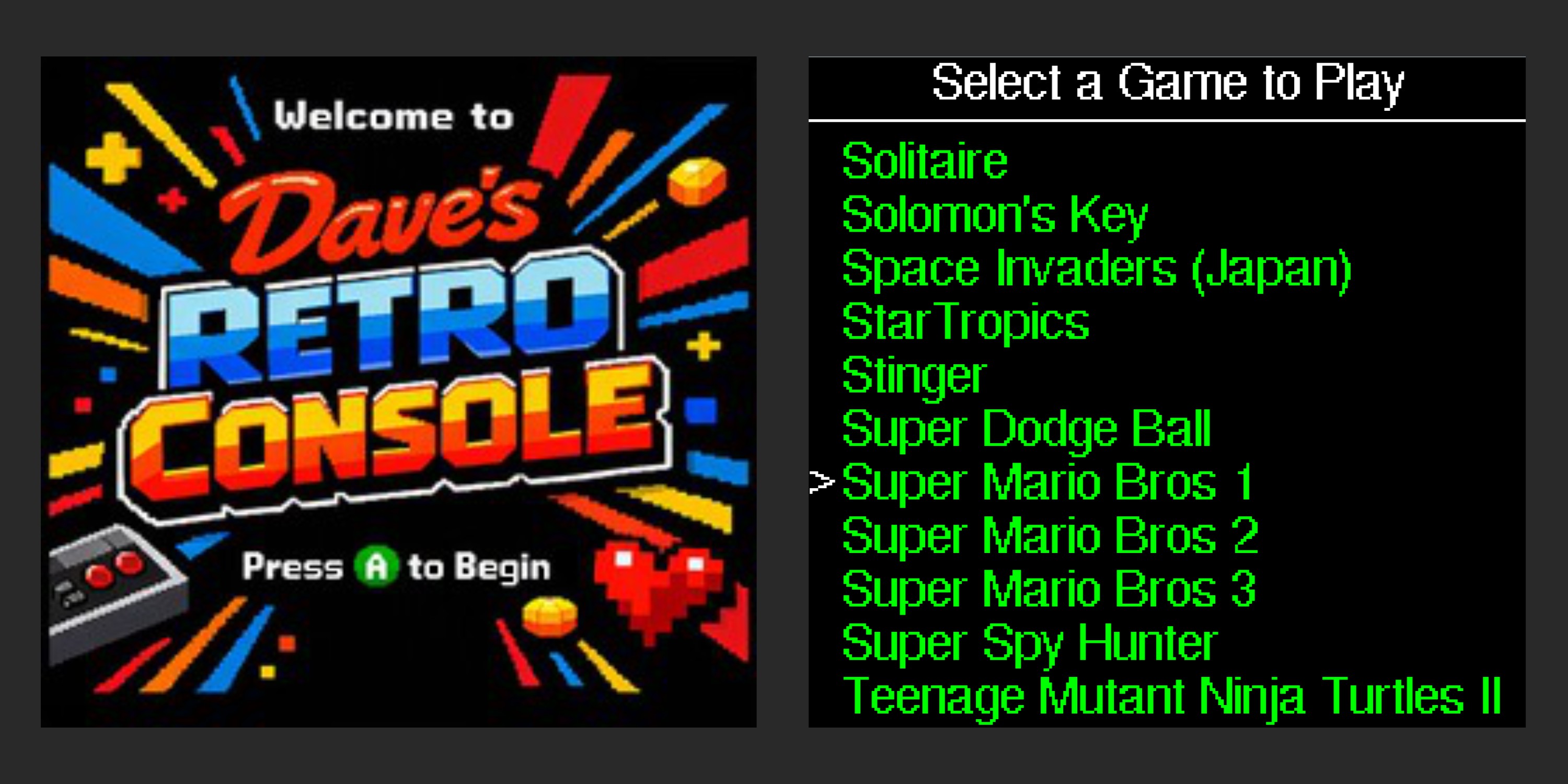
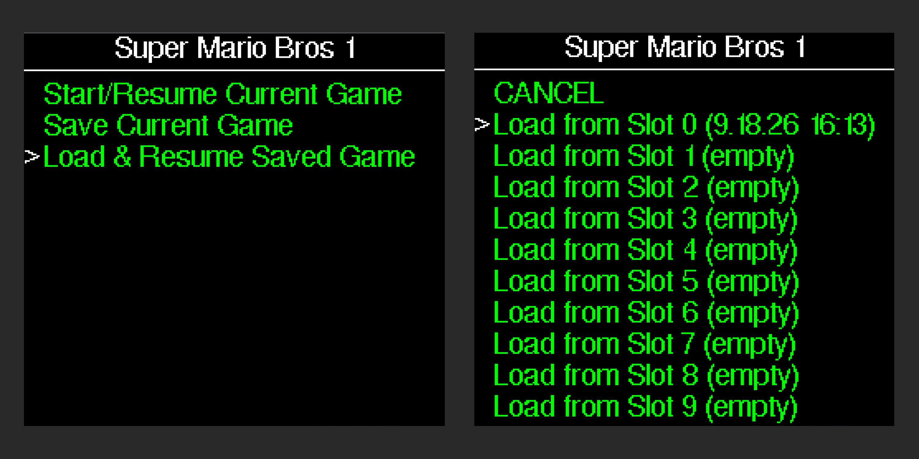
Power it up and, about 30 seconds later, the display comes to life with a classic Press A to Begin splash screen. The menu system lets you browse games, start a new one, or continue from one of up to ten save slots per game. Just like a console should be: turn it on, pick a game, and play.
The splash screen artwork was created by AI, then converted into a bitmap at the display's native 256 × 256 resolution.
Hardware Overview
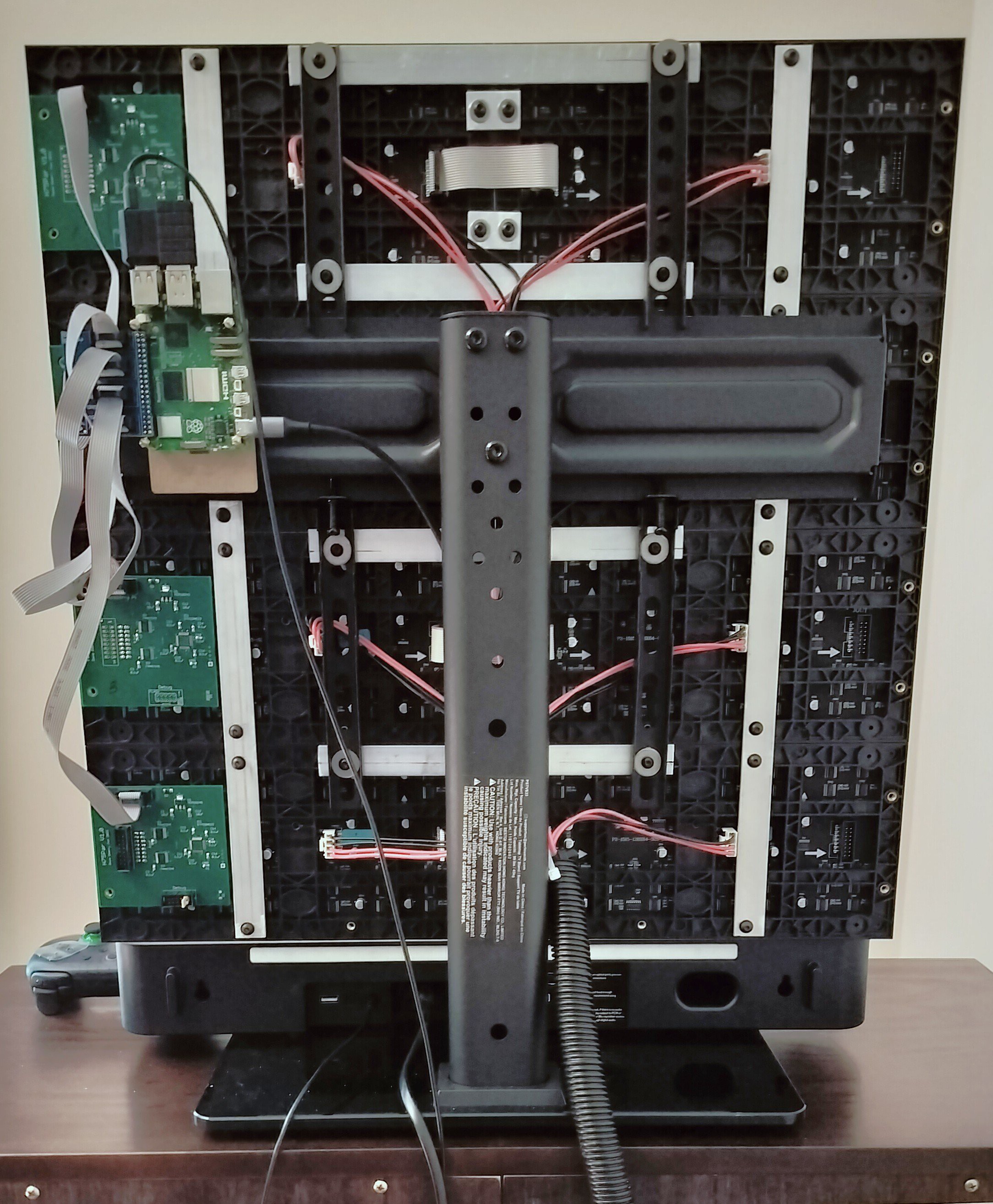
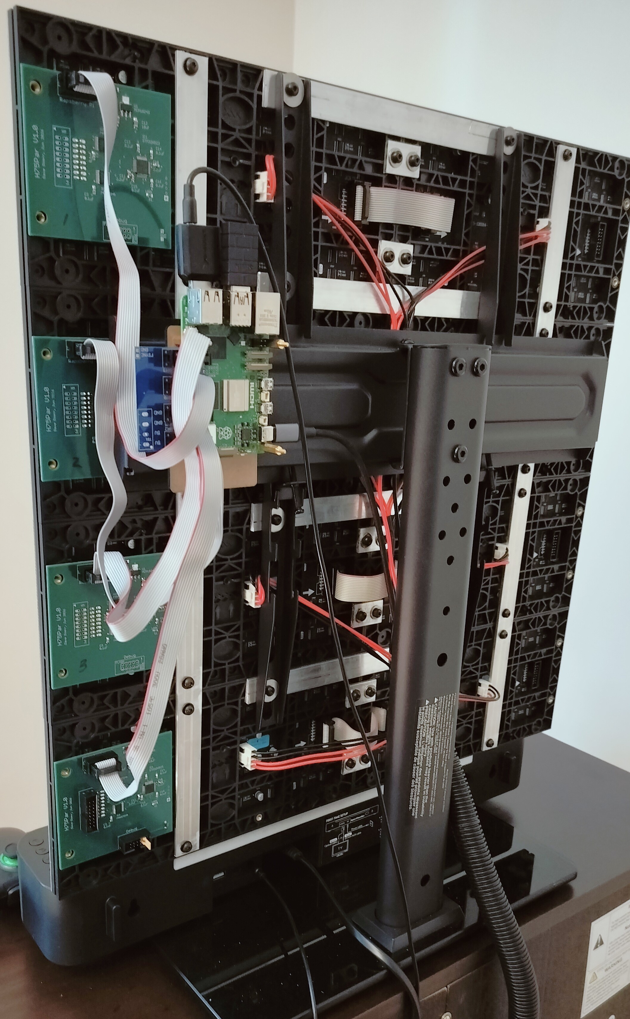
The rear of the console shows the mechanical framework used to combine the eight LED panels into a single 256 × 256 display. The panels are arranged as four rows, with two 128 × 64 panels daisy-chained together in each row. The panels are bolted together using 1/8" × 3/4" aluminum strips and mounted to a PERLESMITH Universal TV Stand.
Five circuit boards provide the electronics:
- Raspberry Pi 5
- Boots directly into the Dave's Retro Console splash screen
- Provides a game selection menu
- Runs the open-source Nestopia NES emulator
- Prepares the video frames for transmission
- Transmits video to the four custom Display PCBs using four SPI interfaces
- Custom fan-out PCB
- Connects to the Raspberry Pi's 40-pin header
- Routes the four SPI interfaces to the Display PCBs through ribbon cables
- Four custom Display PCBs
- Each connects to a pair of daisy-chained 128 × 64 HUB75 panels
- Each controls one complete 256 × 64 horizontal row of the display
- Each receives pixel data from the Raspberry Pi and renders it on the display
The electronics not visible here are:
- A generic 5V-3A USB power supply for the RPi (app only draws about 0.5 A)
- A Mean Well LRS-200-5 5V power supply for the LED panels (oversized, draw is typically less than 10 A)
- A sound bar ($30 from Walmart which has surprisingly good bass)
The 128x64 LED Panels
A 128 × 64 panel is shown below on the left. My custom Display PCB is shown on the right, with front and back views (not to scale). The 16-pin female header on the back plugs directly into the LED panel, eliminating a ribbon cable while also providing a mechanical mount for the board.
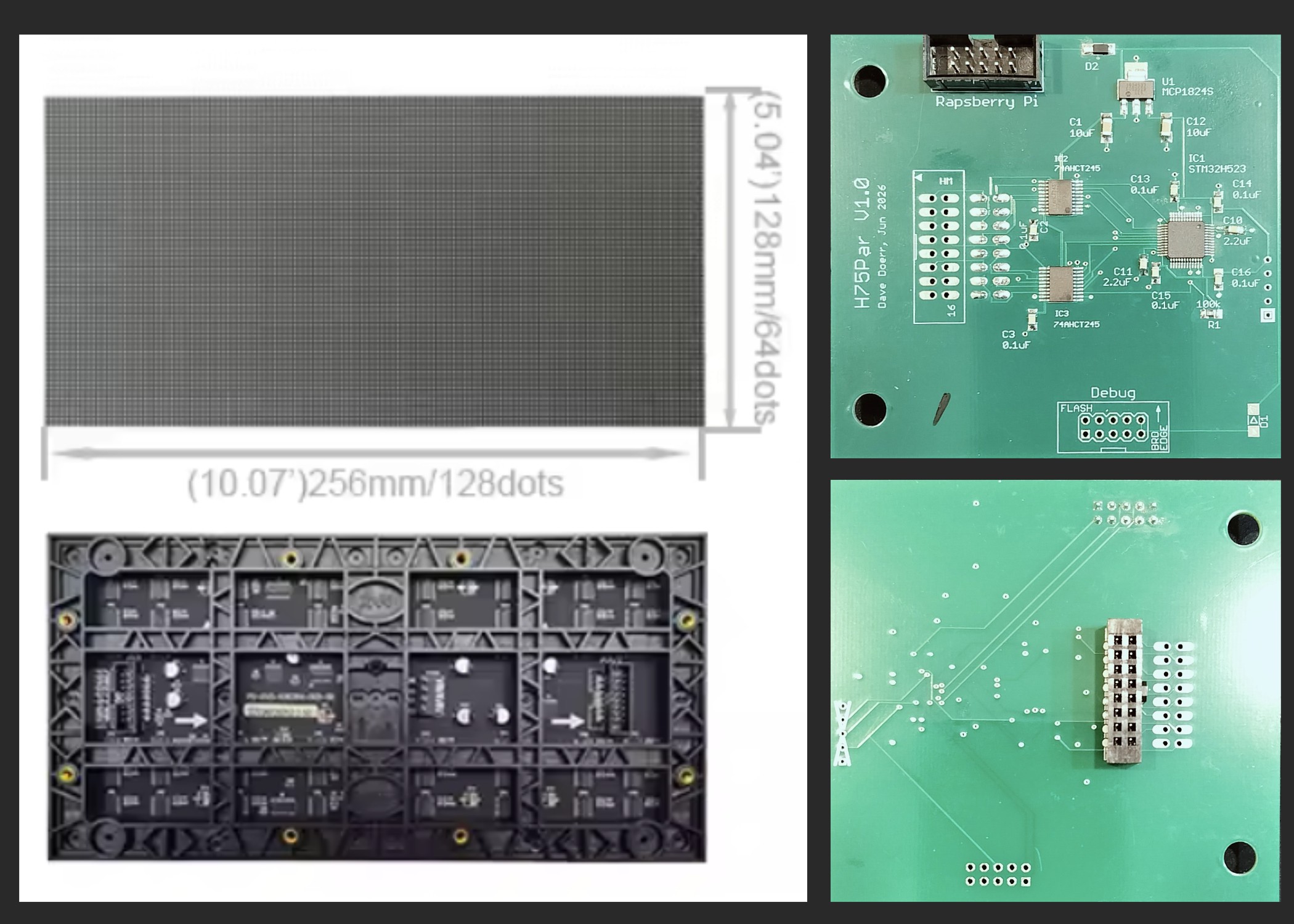
The Display PCBs are pretty simple. Each contains an STM32H523 MCU, a 5V-to-3.3V regulator, and two 74AHCT245 level shifters that translate the processor's 3.3V outputs to the 5V logic levels expected by the HUB75 panels. One board drives two panels and manages all refresh timing and image rendering locally.
My eight HUB75 panels came directly from the manufacturer, Evershine, through their AliExpress store. At under $30 each including shipping, they were considerably less expensive than domestic sources, yet the quality was excellent. I was particularly impressed with their support, which included fast responses to technical questions and the mechanical drawings needed for the design.
A lesson learned during assembly: clamp the panels tightly together before tightening the aluminum support strips. Even gaps that are barely visible during construction stand out once graphics are displayed, making what should be a seamless image look like eight separate panels.
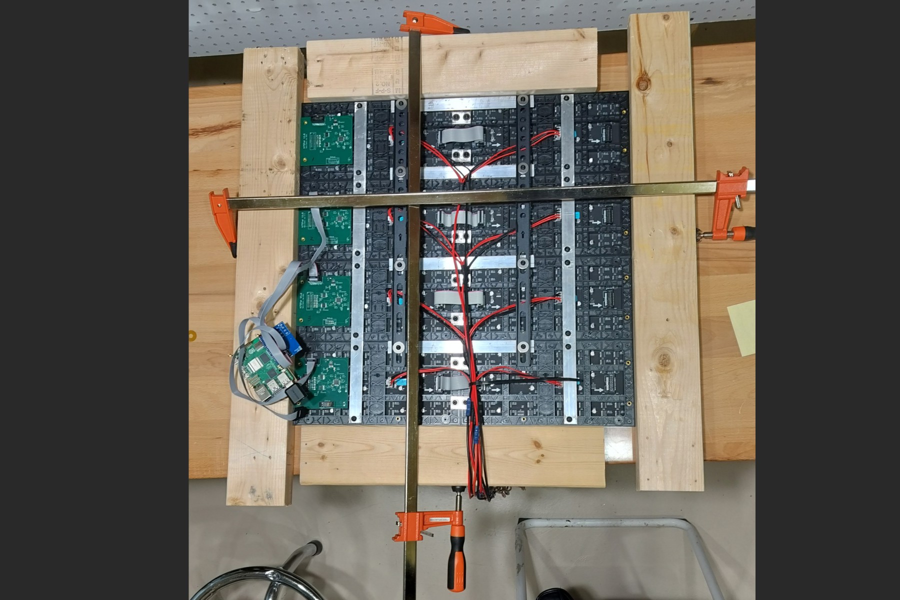
Image Rendering
HUB75 panels are extremely primitive displays. They do not manage brightness, color, image storage, or refresh internally. Only 1/32 of the LEDs can be illuminated at any given moment, and each LED is either fully on or fully off. My Display PCB acts as the display controller, turning LEDs on and off for varying lengths of time to modulate the mix and intensity of the red, green, and blue colors. Persistence of vision in the human eye effectively averages this light output, so no flicker is noticeable as long as the LEDs are refreshed quickly enough.
I originally intended to use one Display PCB for each panel. However, because the Raspberry Pi...
Read more »
 Michael
 PixelCircuits
 Tim Savage
 retrobyte