Project logs:
I bought an estate sale TI-99/4A, but it was missing the external power brick. What now?
To make the experience fit your profile, pick a username and tell us what interests you.
We found and based on your interests.
barreljack_remix_2.stl3d model for barrel jack bracketStandard Tesselated Geometry - 16.59 kB - 09/20/2026 at 23:13 |
|
|
Artwork.pngPortable Network Graphics (PNG) - 107.27 kB - 09/20/2026 at 20:53 |
|
|
pcb final 4.svgsvg+xml - 46.77 kB - 09/20/2026 at 20:52 |
|
|
pcb edit 3.svgsvg+xml - 100.37 kB - 09/20/2026 at 20:52 |
|
|
pcb edit 1.svgsvg+xml - 79.68 kB - 09/20/2026 at 20:51 |
|
|
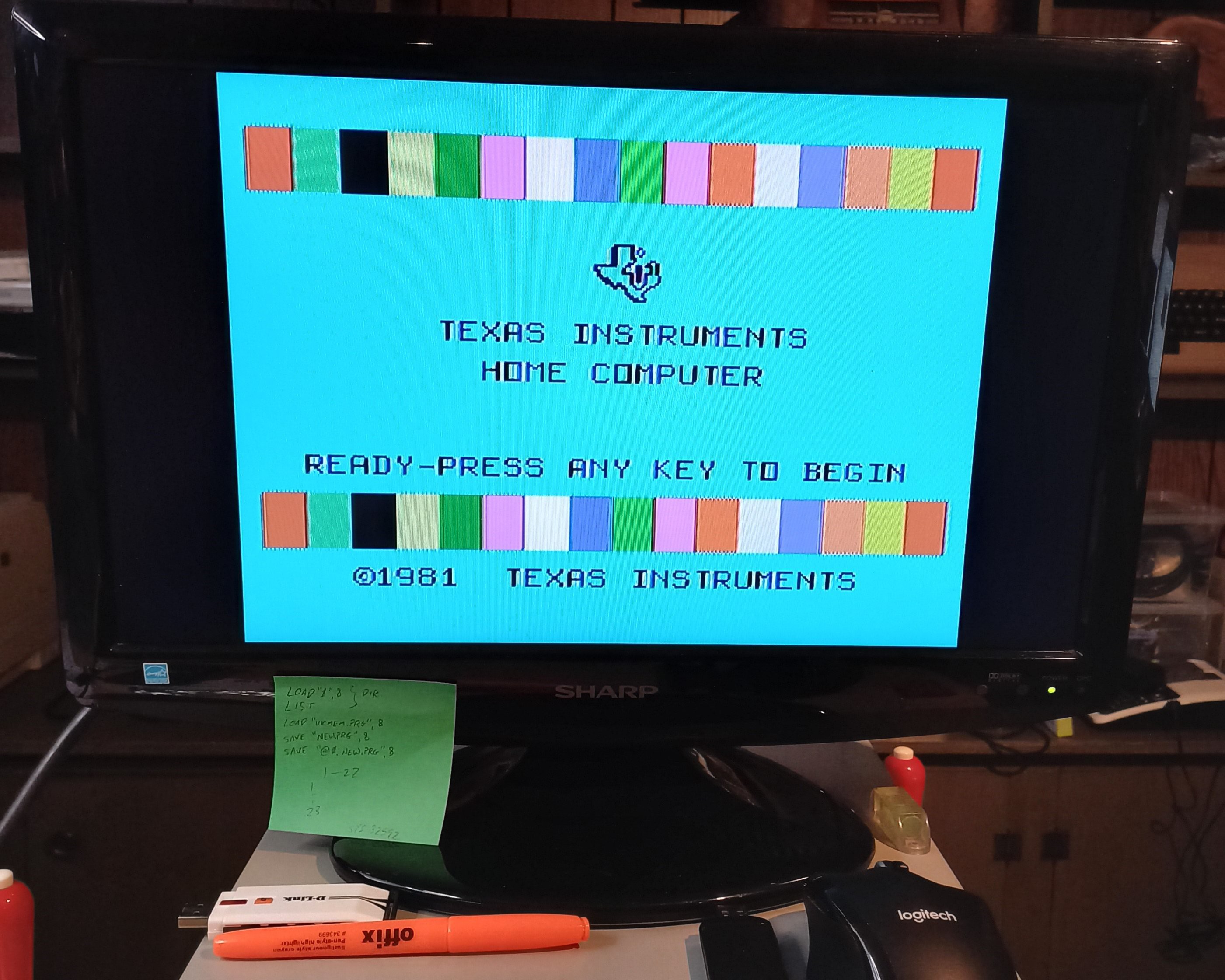
This was a pretty satisfying project. I learned how those small three-terminal switching supply modules work (basically like the linear regulators, but without the inefficiency), and I resurrected an otherwise dormant machine. I still have it in my collection, but I have zero software for it. Maybe I'll find some someday.
In the meantime, I want to try to interface an old period-correct SONY cassette deck to it, so I will at least be able to store and retrieve programs.
Incidentally, I retained all the original parts, so future owners will be able to restore the TI to its original stock configuration.
Happy retro-computing! Press any key to begin!
The final step was to determine how to bring 19vdc into the TI-99/4A chassis.
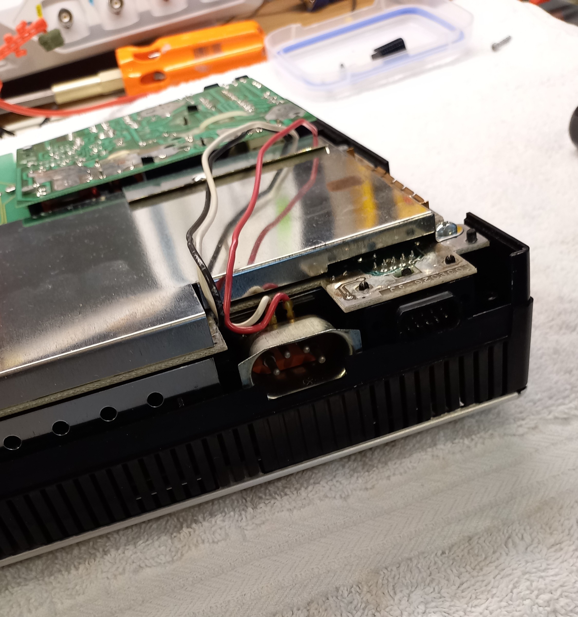
Below is a shot of the internals where AC power comes into the stock machine from the standard brick:
I obviously did not want to reuse that connector, because someone in the future might come along and plug a standard TI brick in there. It would probably not work and/or start a fire.
(I mis-spoke in an earlier log, it's not mains coming in, but it is a set of stepped-down AC voltages. I will try to correct the log).
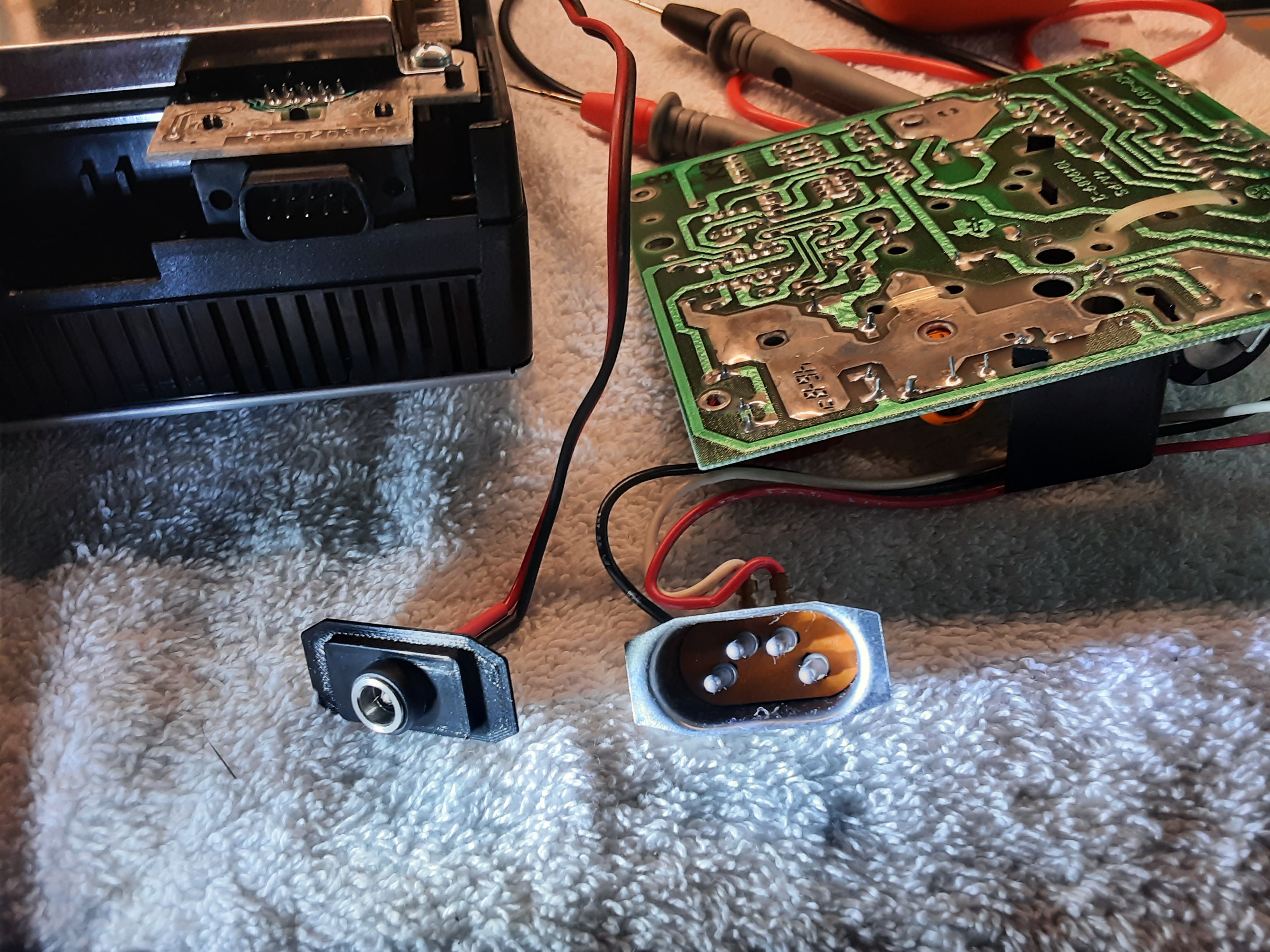
The solution I came up with was the design and 3D print a plate/bracket for a barrel jack sized correctly for my laptop supply. I did find another maker out there with a version of this, but it was not a good fit. This is the result, new on the left, original on the right:
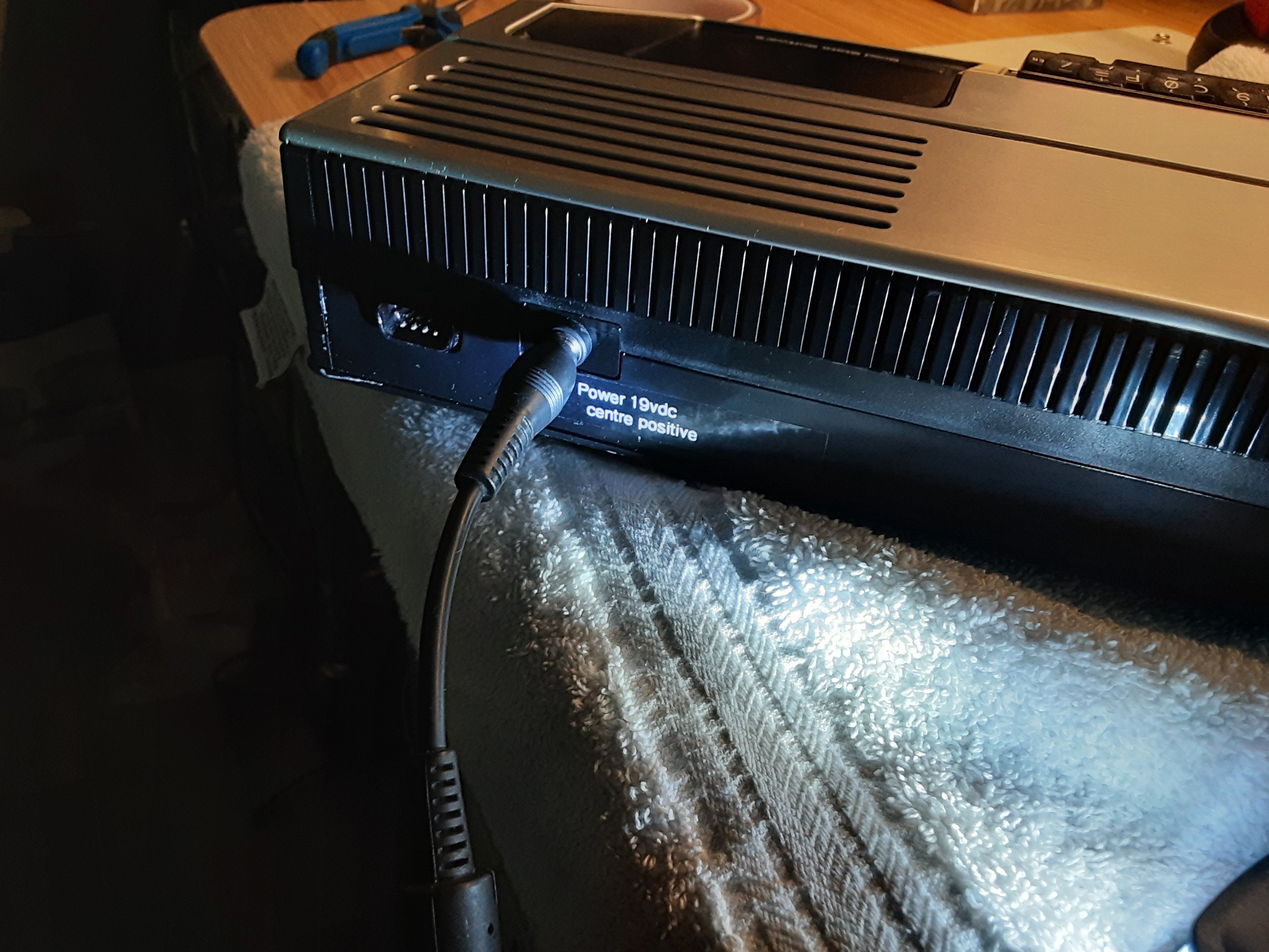
This is how it looks with the case all buttoned up:
You can find the stl for that bracket here: Printables
The circuit I would use to build the power supply was pretty simple, and would be easy to implement with a single-sided board. Given that, and the fact I had the materials left from previous projects, I tried and eventually succeeded in creating a single-sided layout on a copper-clad board.
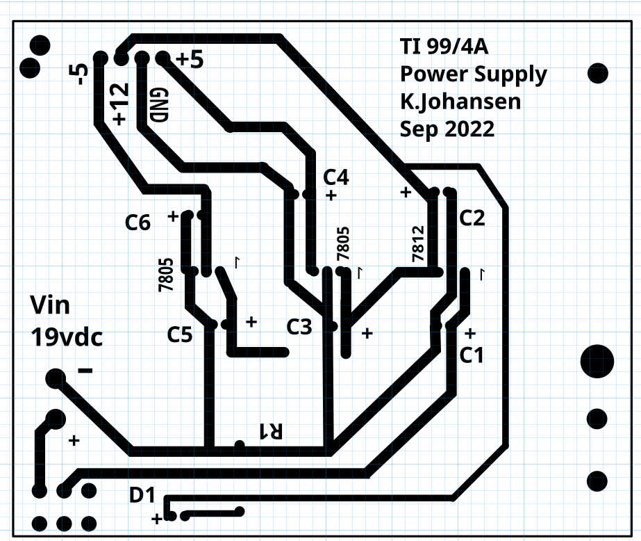
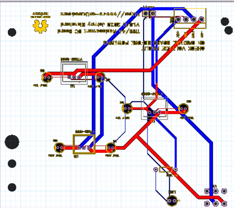
I used Inkscape to draw the board. Inkscape is useful for this, as it will accurately maintain and produce output with the correct dimensions. Below is the artwork in its final version:
I used the glossy paper/laser printer method to create the mask. You use a household clothes iron to transfer the laser toner onto the board, then use ferric chloride etchant to remove the excess copper.
This took a number of tries, as the ironing method sometimes leaves gaps where they shouldn't be. It eventually worked.
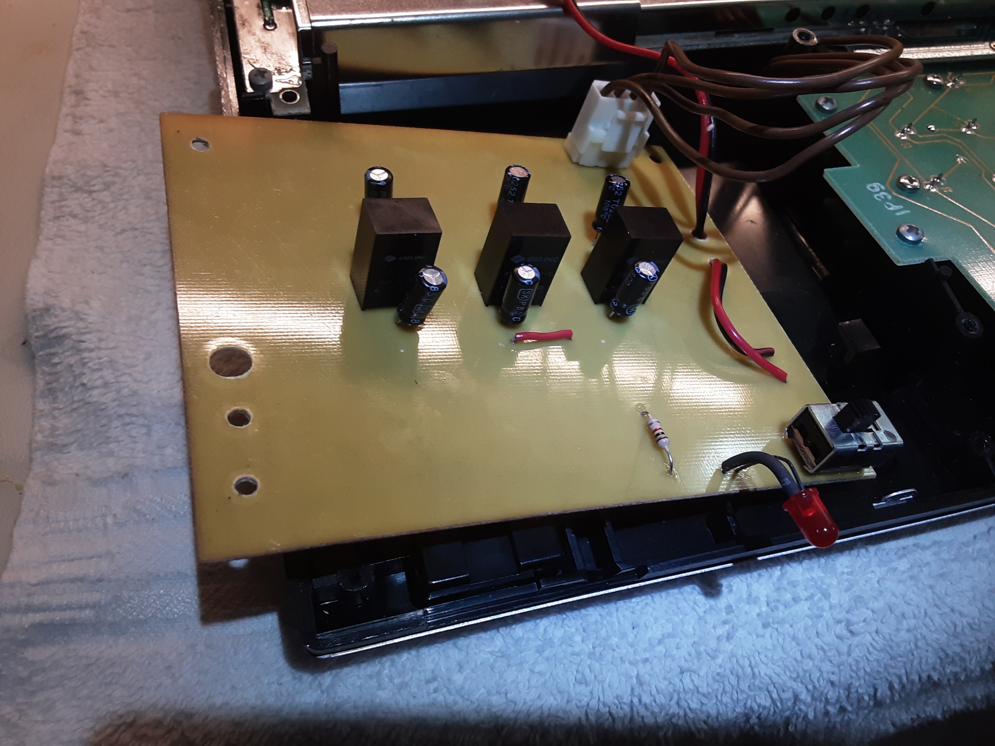
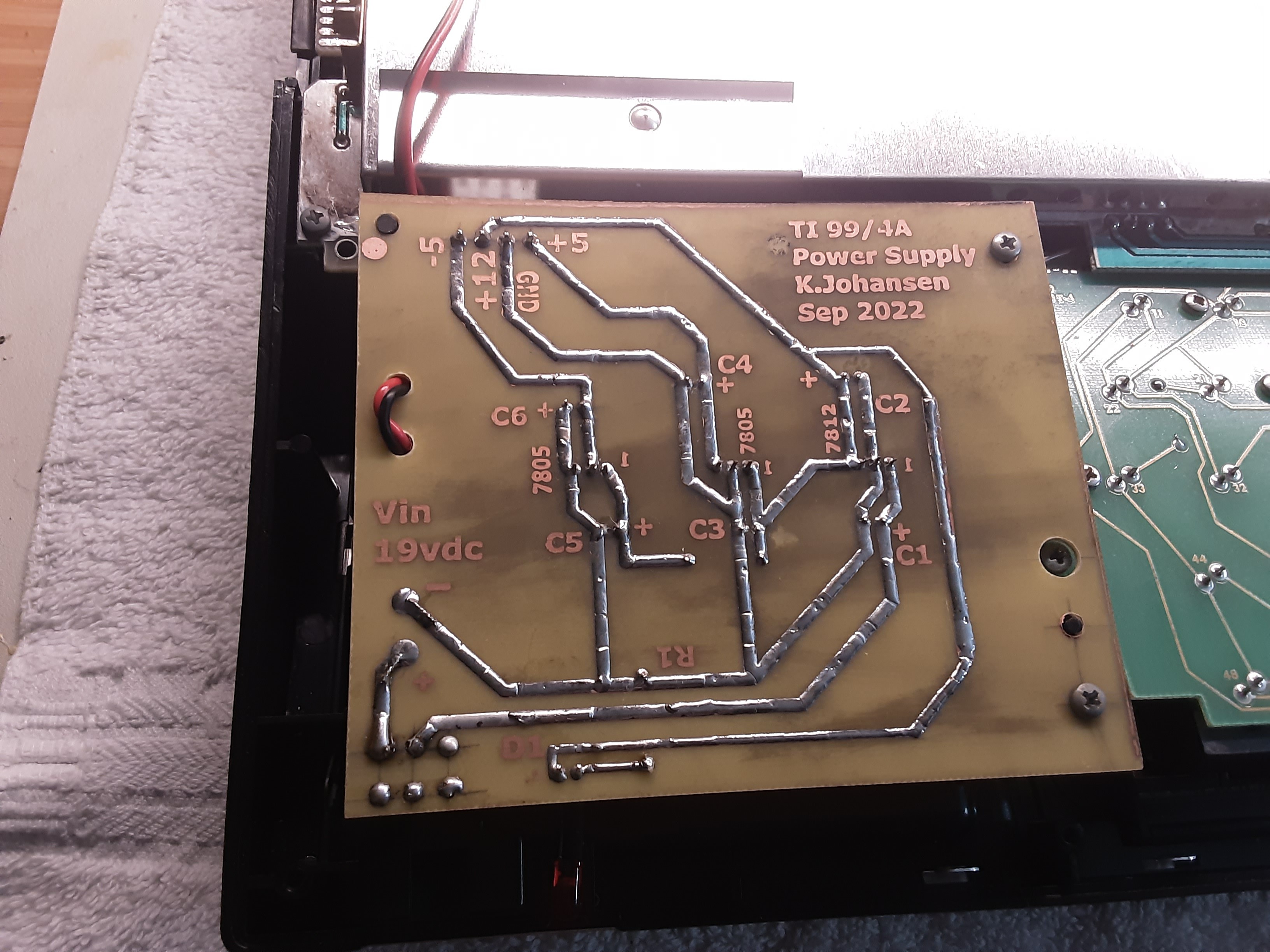
Below is the resulting board, plugged in for testing. As mentioned, the header on the top right and the switch and LED on the bottom right were scavenged from the original PCB.
I added lots of solder onto the traces just to boost the current-carrying capacity. Plus, it was a fun and relaxing activity.
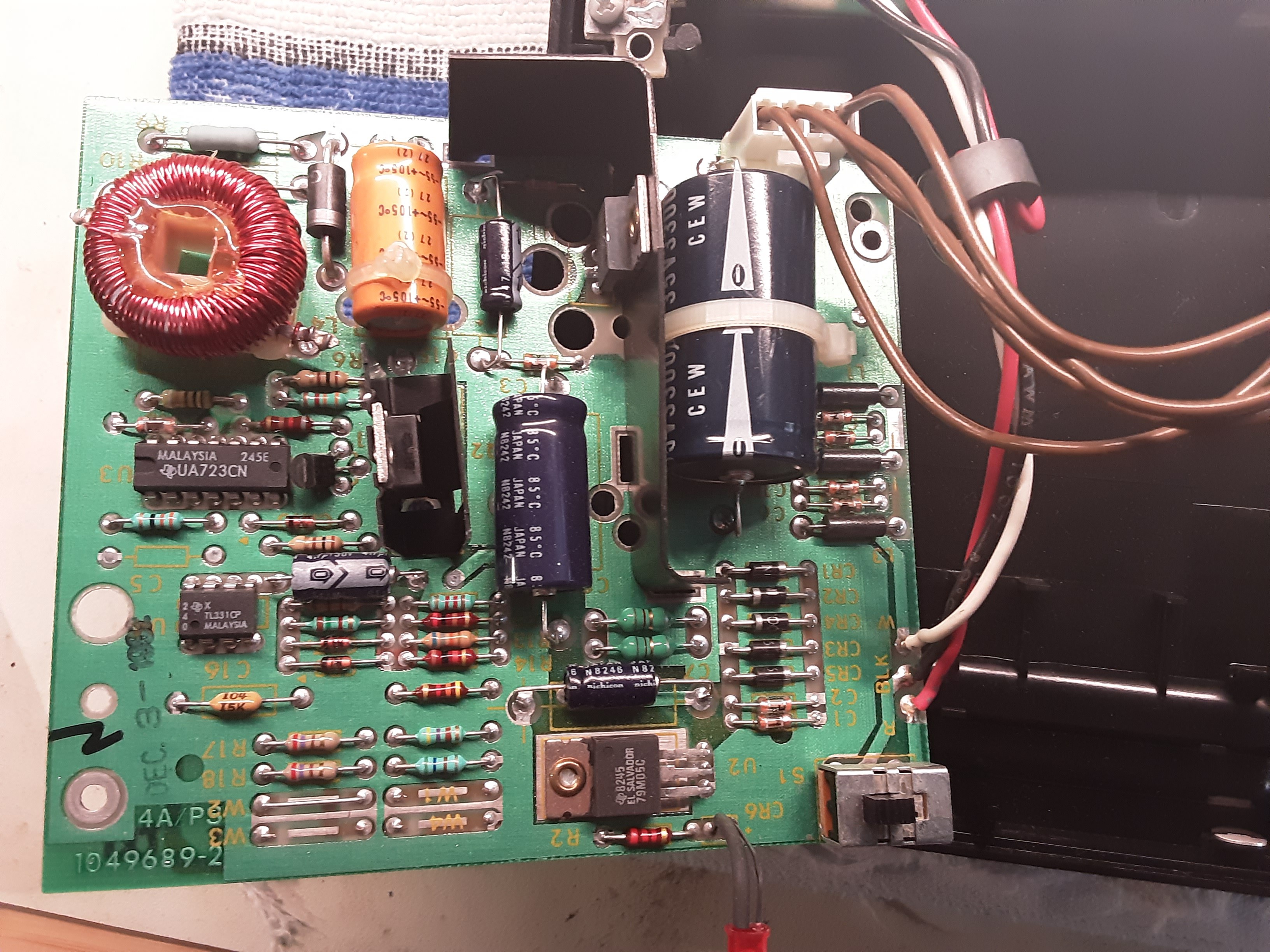
Below is a shot of the original Power Supply board in question.
It brings AC voltages into the machine, rectifies and regulates it to deliver +5v, +12v and -5v to the motherboard. A lot going on here, and no point in trying to replicate it. As long as the replacement delivers the right voltages, with enough current capacity.
I have lots of 19vdc laptop power bricks around, with standard barrel jacks. So, that's where I was going for a primary source of power.
Below is a shot of the pcb designed by my predecessors:
(Apologies for the quality). I didn't use their exact circuit, but the board layout was dimensionally compatible with original in terms of size, mounting holes, and pcb footprints for the switch and output header that I would eventually steal from the old board. It was therefore useful for designing my own PCB.
Would this computer even boot?
Taking what others had done before me, I went with a series of modular buck converters to derive the +12v, +5v and -5v supplies expected by the machine.
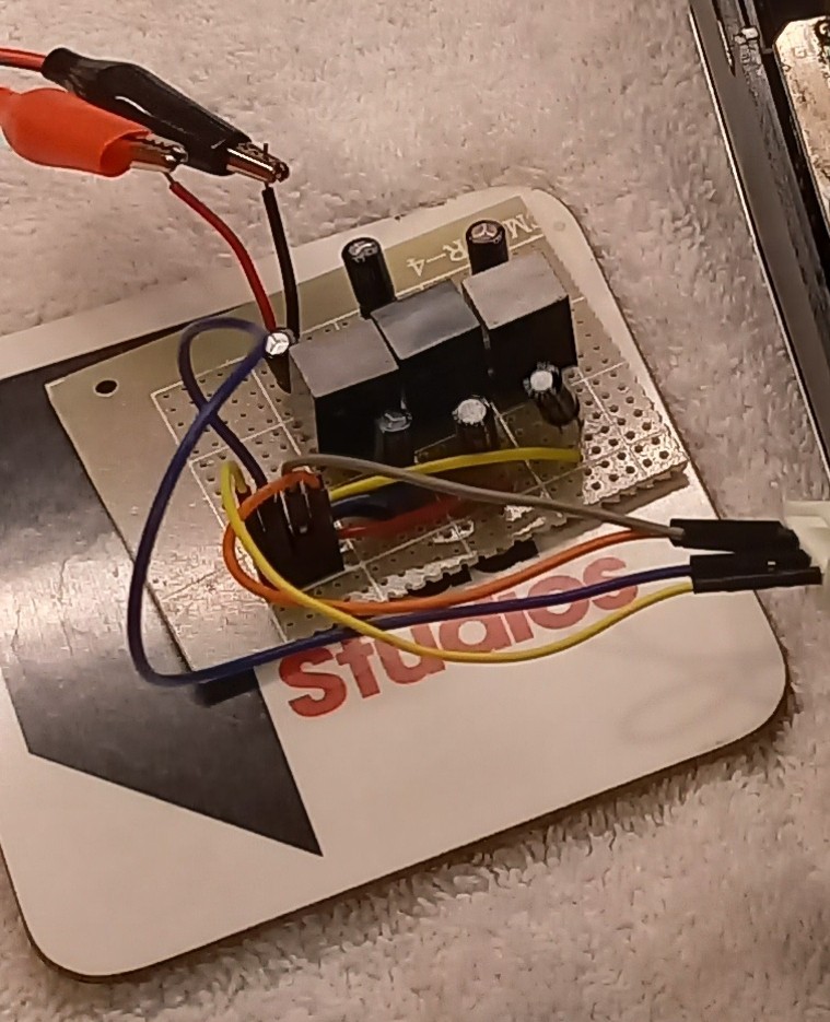
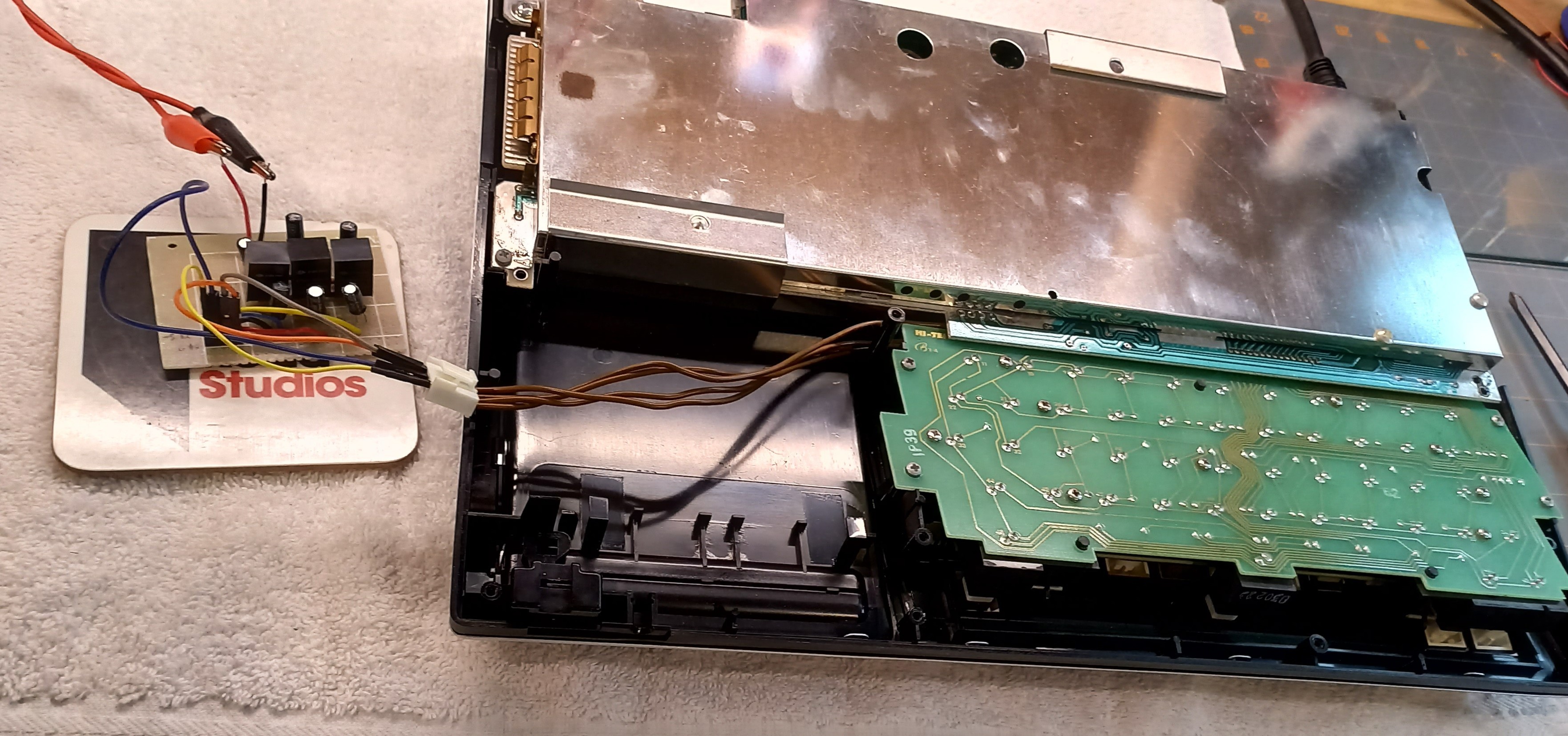
I installed them on a small protoboard, jumpered into the TI's power header, and sure enough, I had a working machine. Yay!
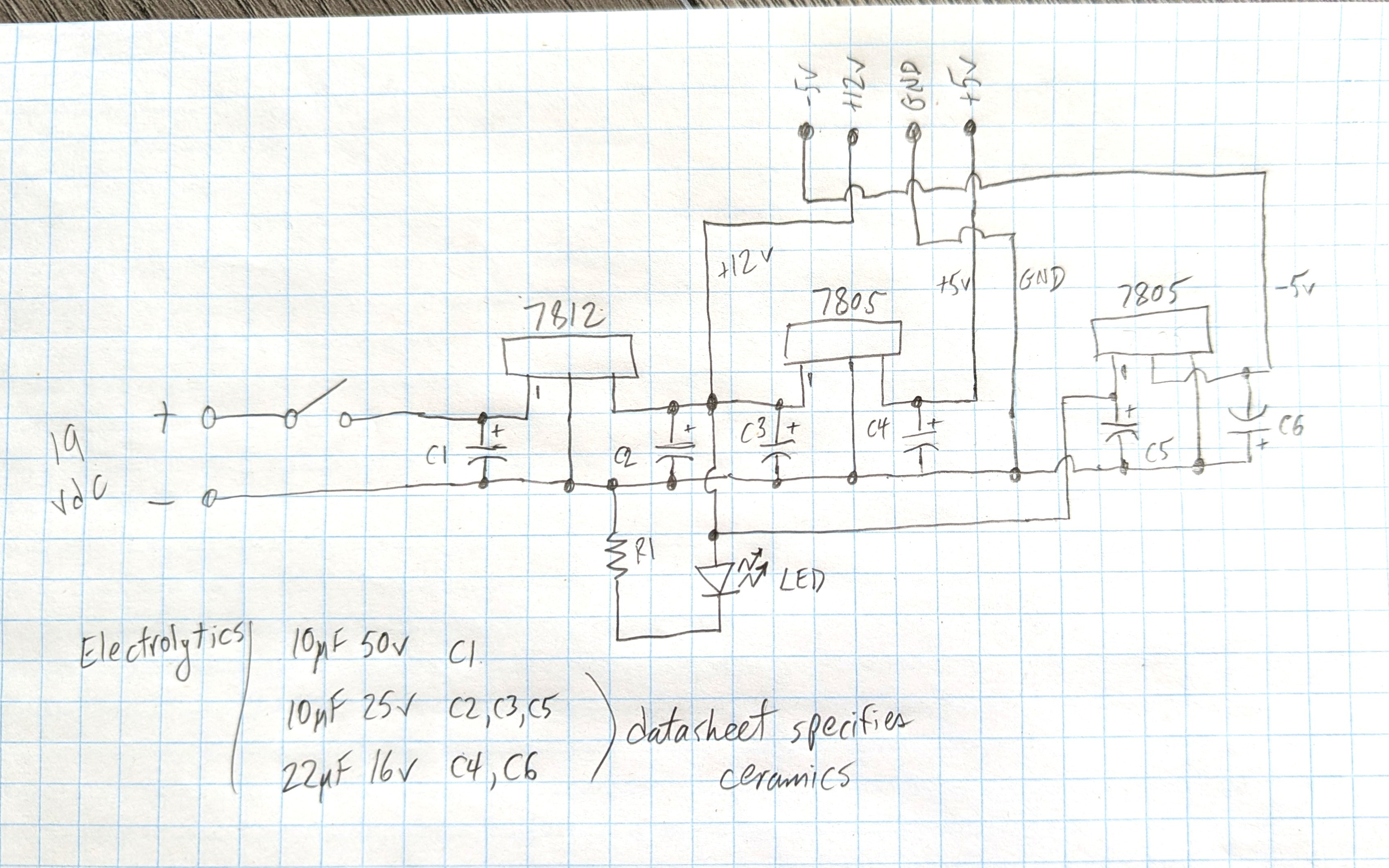
The datasheets for these devices specify ceramics, but I went with electrolytics for some reason. I guess I'm used to working with linear regulators which usually get electrolytics on the inputs and outputs.
Below is the schematic:
Create an account to leave a comment. Already have an account? Log In.
Become a member to follow this project and never miss any updates
Adam Demuri
Dave's Dev Lab
haas
rawe