 Shubhan Mital
-
1Assembling the Robot Arm Kit
Follow the instructions in the official video from the kit to assemble the arm
-
2Understanding the Robot Arm and its Servos
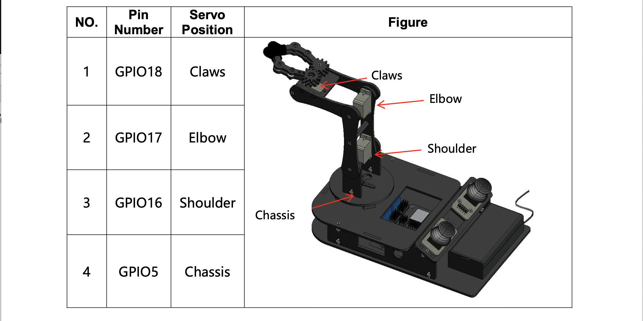
The ACEBOTT QD022 arm moves with four MG90 servo motors, one at each joint. A servo is a small motor that turns to a precise angle (0°-180°) when it receives a control signal, which is what lets the arm move to exact positions. Together, the four joints let the arm reach, lower, trace and grip.
How to connect and test the servos
- Plug each servo cable into its matching pin header on the ESP32 board, following the table above. The brown/black wire goes to GND, red to power, and orange/yellow to the signal pin.
- Install the ESP32Servo library in the Arduino IDE (Library Manager → search "ESP32Servo").
![]()
-
3Wiring and Pin Connections
It is important to note which pins to connect the wires coming out of the servos to.
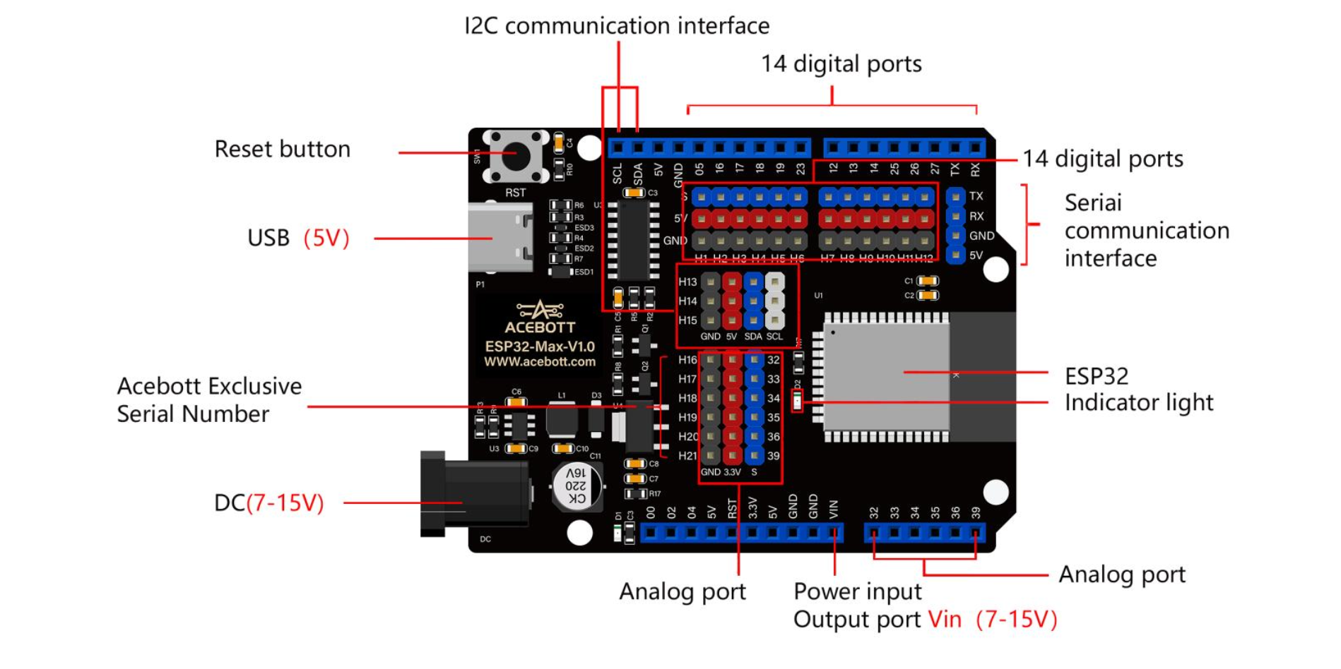
Below is the ESP32 Max V1.0, the controller board that comes with the ACEBOTT kit and drives our arm's servos. The rows of pin headers along the top edge are where the servos plug in. Each column has a signal pin (blue), a 5V pin (red) and a GND pin (black), with its GPIO number printed above. The board can be powered through its USB-C port (5V) or the DC jack (7–15V), and the serial pins on the right (TX/RX) are how it can talk to other boards like the Arduino UNO Q.
![]()
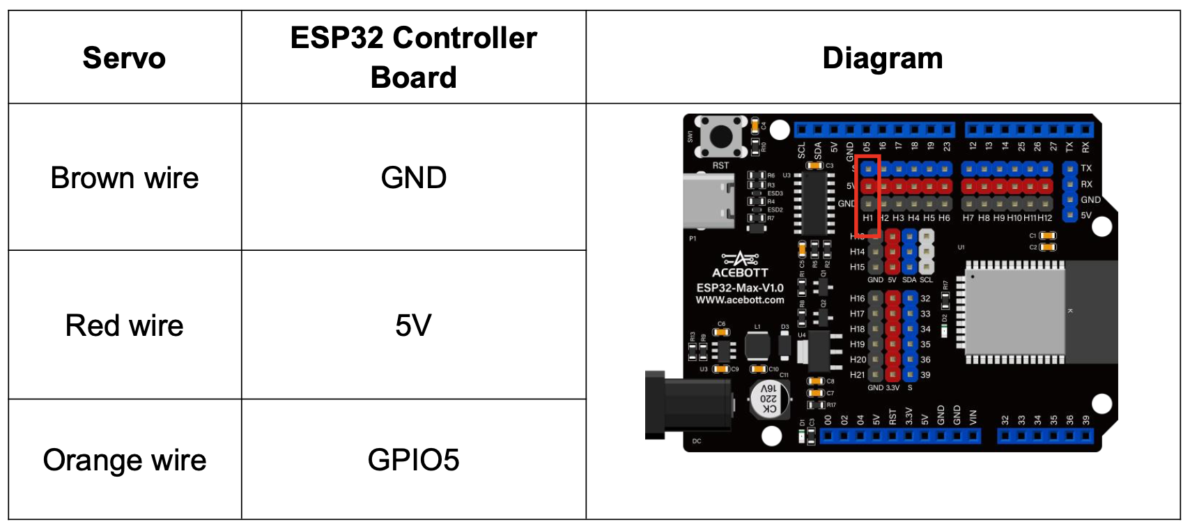
Each servo has three wires: brown goes to GND, red to 5V, and orange to the signal pin. This example shows the chassis (base) servo plugged into GPIO5. Connect the other servos the same way: shoulder to GPIO16, elbow to GPIO17 and claw to GPIO18. Make sure the brown wire always faces the black GND row, because a servo plugged in backwards won't move.
![]()
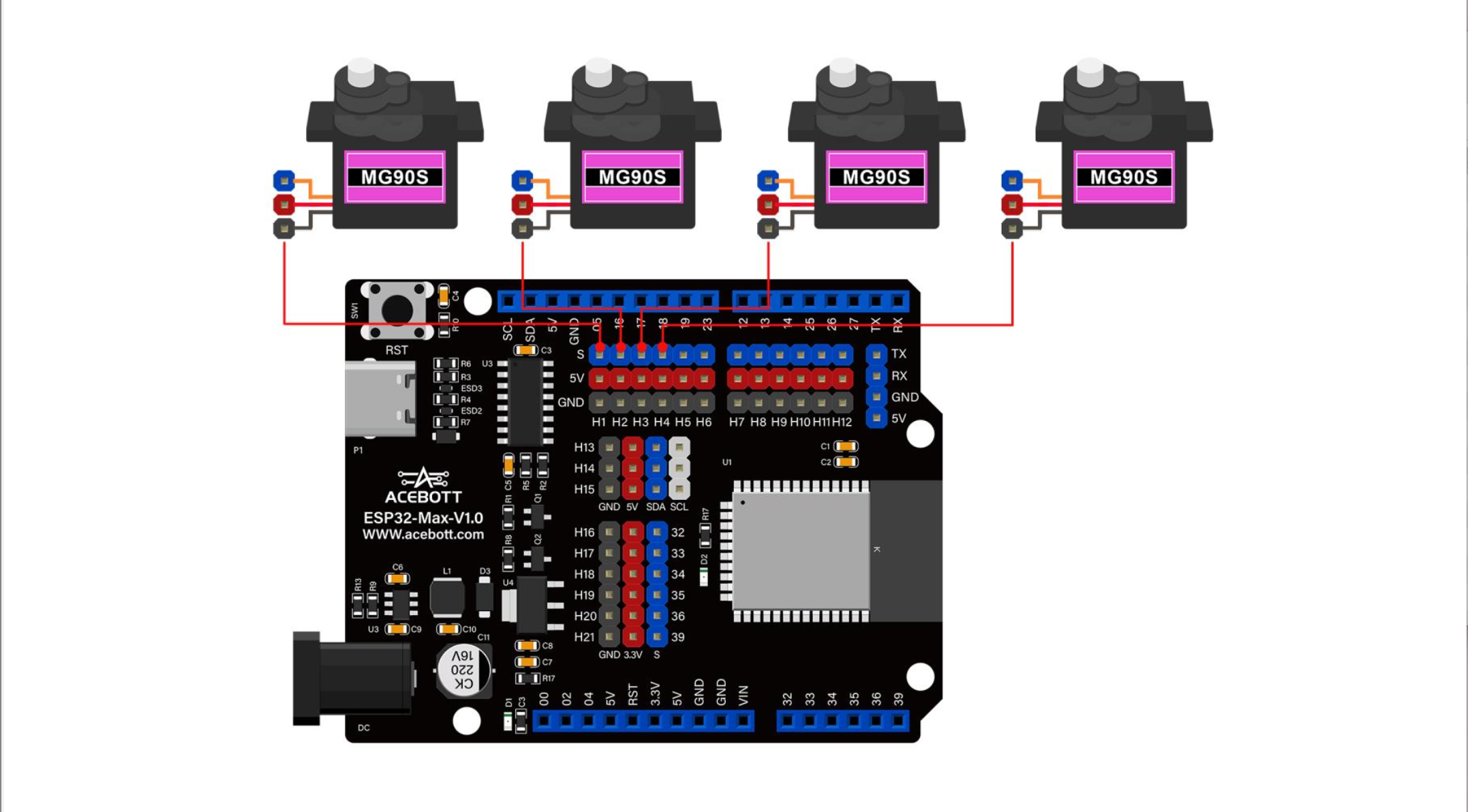
This diagram shows all four MG90S servos connected to the ESP32 Max board at once. Each servo plugs into its own three-pin header in the first four columns of the top row (H1–H4), which match GPIO5, GPIO16, GPIO17 and GPIO18: the chassis, shoulder, elbow and claw. Every header supplies power (5V) and ground (GND) alongside the signal pin, so each servo needs just one plug and no extra wiring. Once all four are connected, the ESP32 can control every joint of the arm on its own, taking movement commands from the Arduino UNO Q.
![]()
-
4Using Computer Vision
Mount the webcam on and train the AI model to accurately identify the marker, which is the target object in our case. Also make sure that the model does not detect obstacles in the frame.
EWNA Hackathon Team 1 (Team Marker My Words)
A 4-DOF arm on an Arduino UNO Q that sees a hand-drawn line, picks up a marker, traces it, dodges obstacles live, and puts the marker back.
Discussions
Become a Hackaday.io Member
Create an account to leave a comment. Already have an account? Log In.