Shubhan Mital
-
Some Images
18 minutes ago • 0 comments![]()
![]()
![]()
![]()
![]()
![]()
![]()
![]()
![]()
-
Our Final Prototype
19 minutes ago • 0 comments![]()
![]()
![]()
-
Putting the Path Planner to the Test
27 minutes ago • 0 comments![]()
![]()
-
Making the Marker Stand
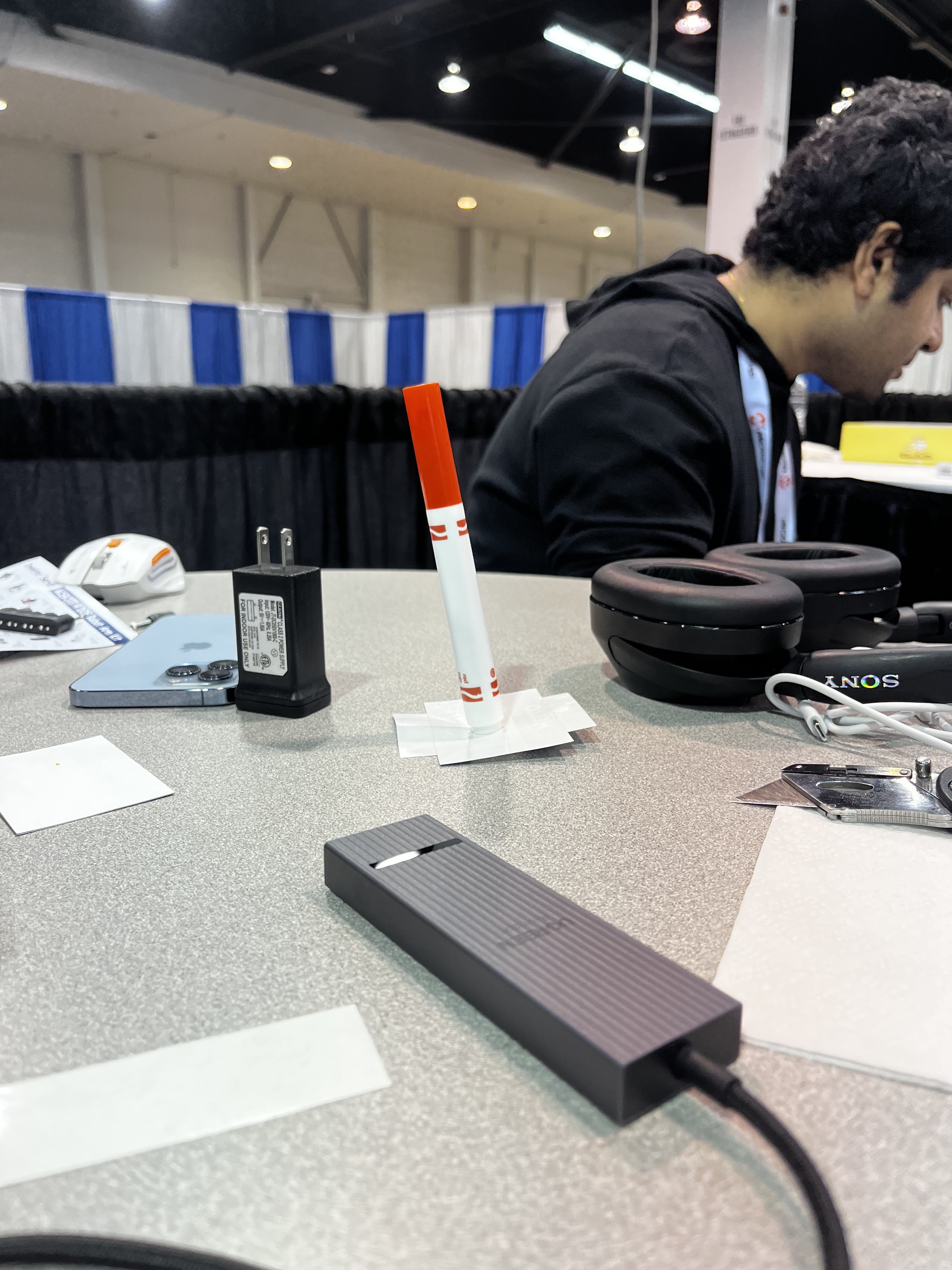
28 minutes ago • 0 commentsA stable base from our name tags. We cut up the "Hello, my name is" name tags from the hackathon badges and layered them into a small, flat platform under the marker. The sticky backing holds the marker's base in place, and the wider footprint keeps it standing upright. Now it stays put until the arm picks it up, and it gives the marker a clear, consistent starting spot to return to.
![]()
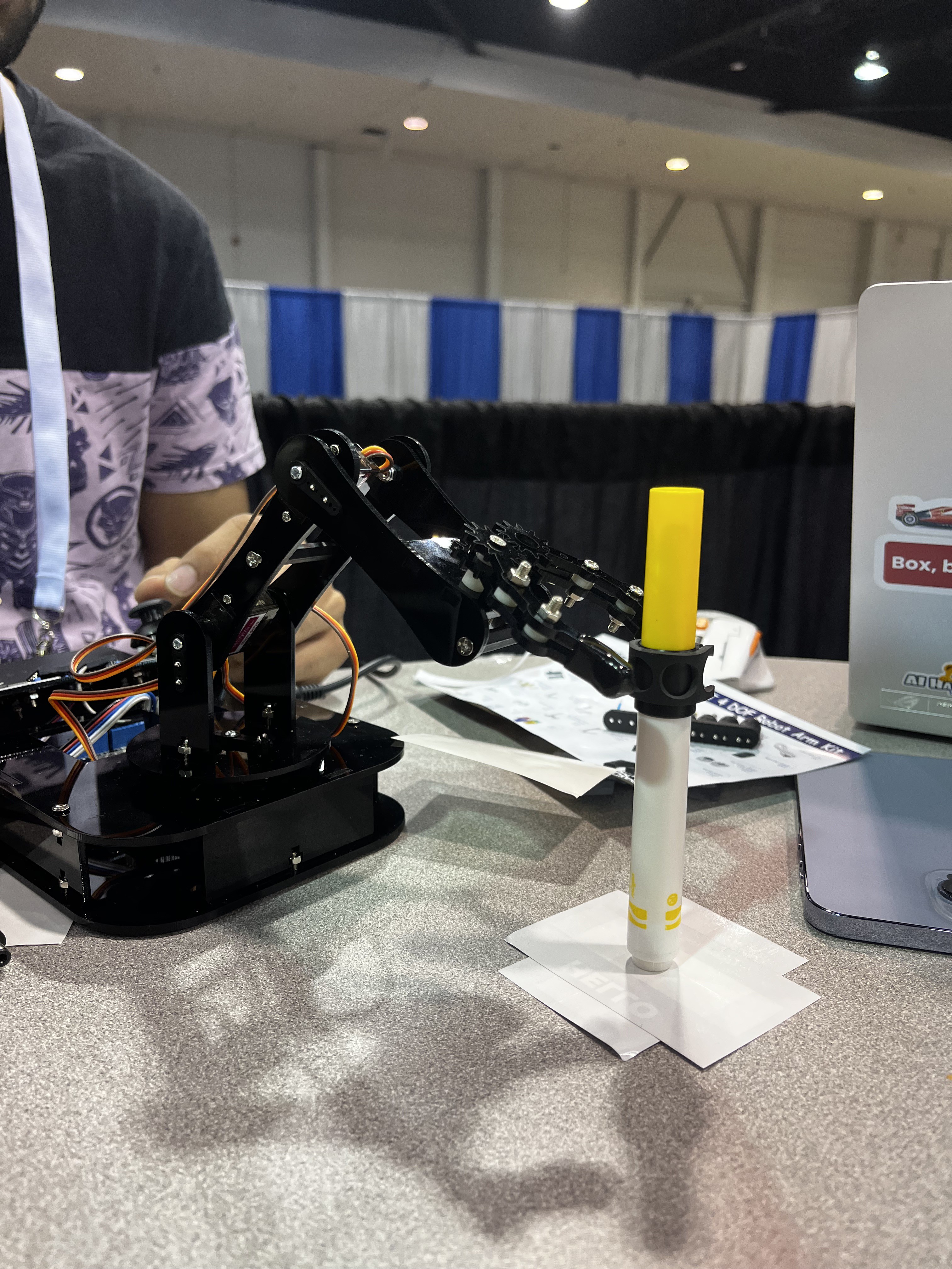
Better grip from the kit's leftover anti-slip sleeve. The ACEBOTT kit came with a spare non-slip sleeve that we used during assembly. We slid it onto the marker where the gripper grabs it. The rubbery surface gives the claw much more to hold onto than smooth plastic, so the marker doesn't slide or twist when it's lifted, and it stays pointing straight down while tracing the line.
![]()
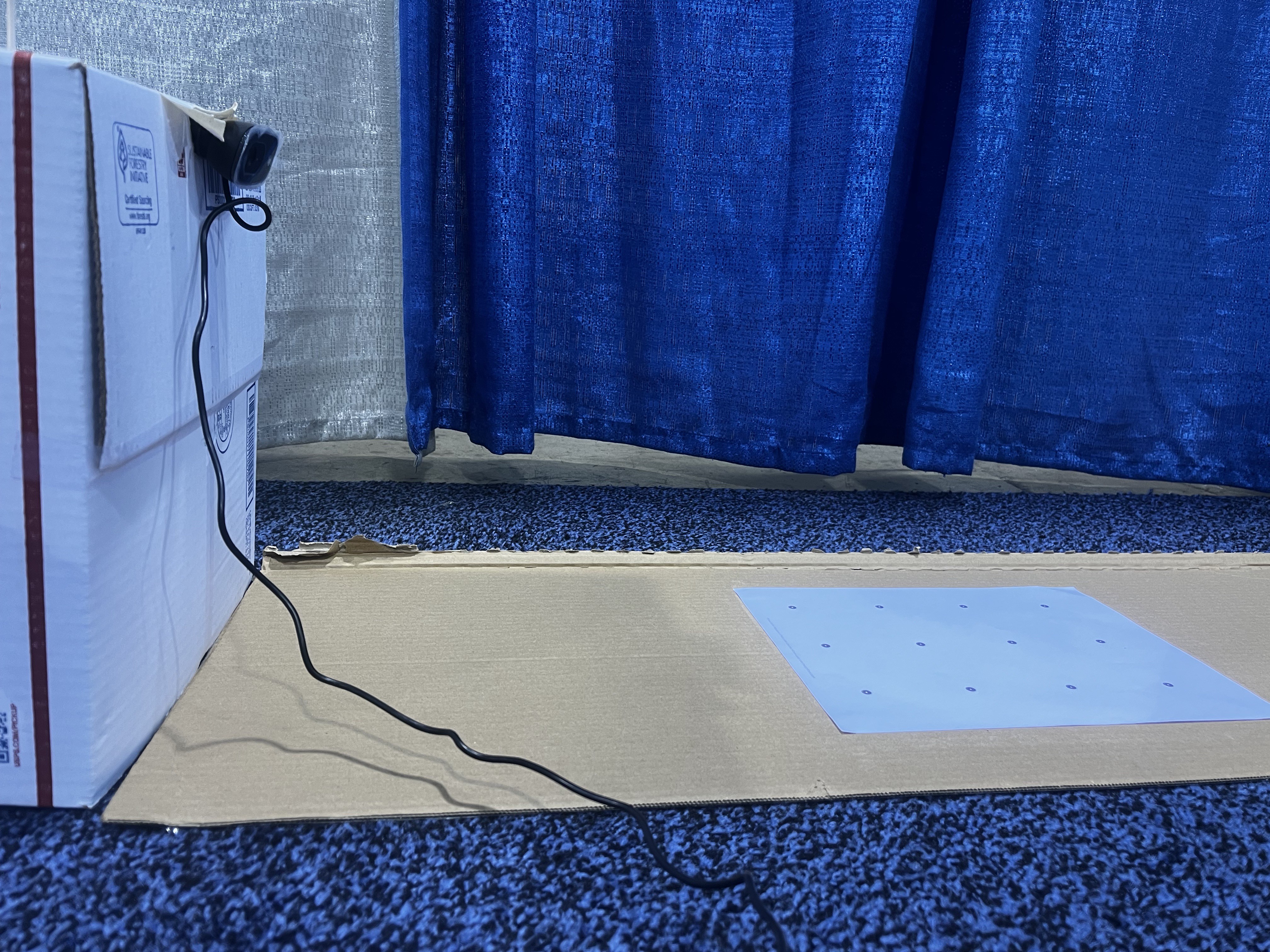
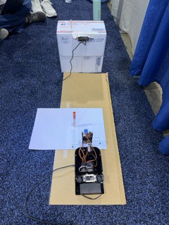
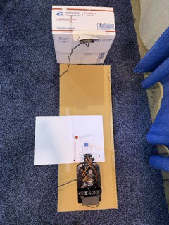
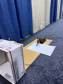
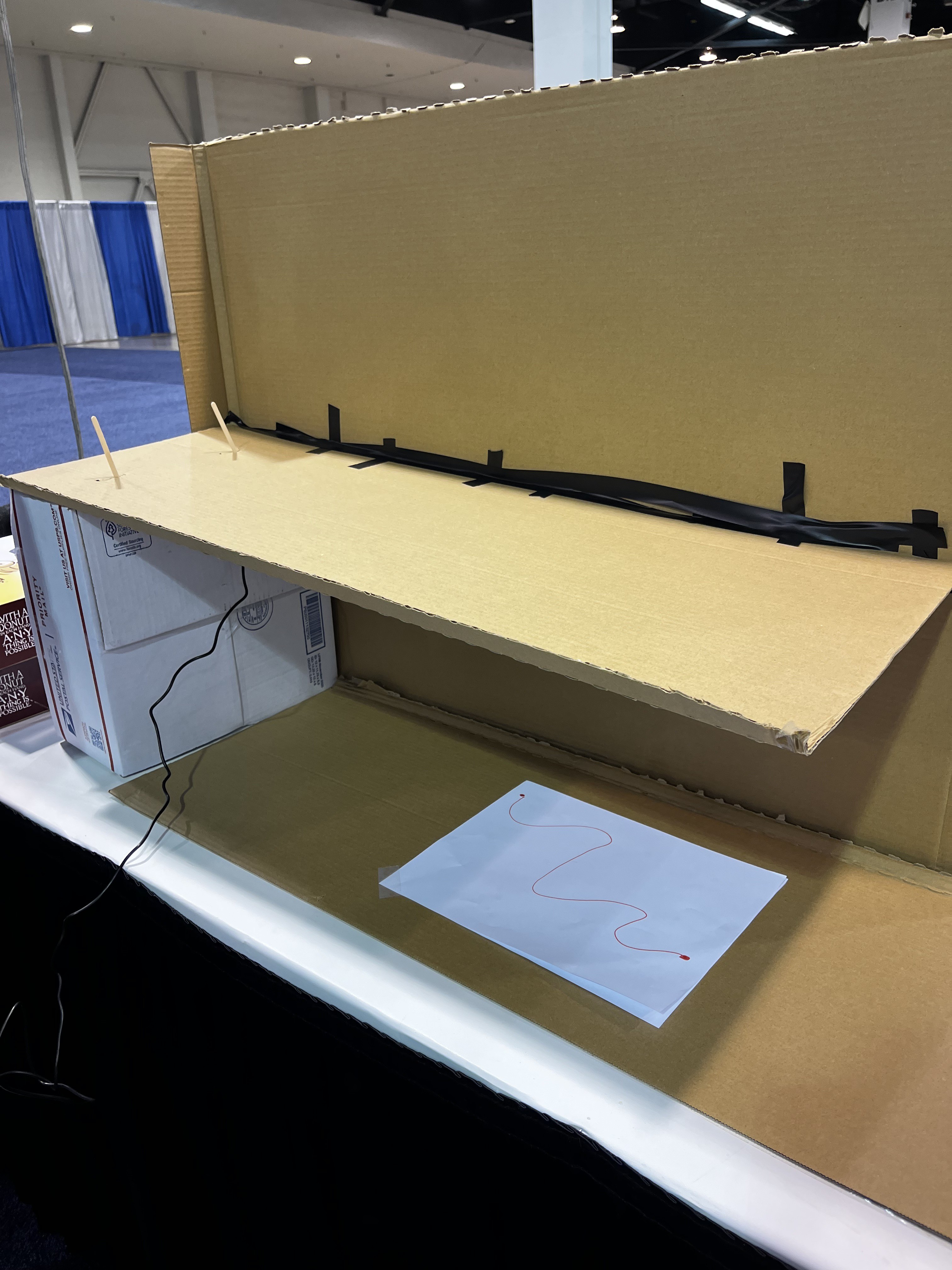
Bonus: a cardboard camera rig. Our overhead camera mount is made entirely from leftover shipping boxes: a cardboard shelf held up by a box, with craft sticks and electrical tape keeping the camera and its cable in place. It isn't glamorous, but it holds the camera steady at a fixed height, and that's all the calibration needs.
![]()
-
Talking to the ESP32
37 minutes ago • 0 commentsOur system has two jobs: working out where the arm should go, and making the servos actually get it there. The ESP32 handles the second. Here's how the two sides talk to each other.
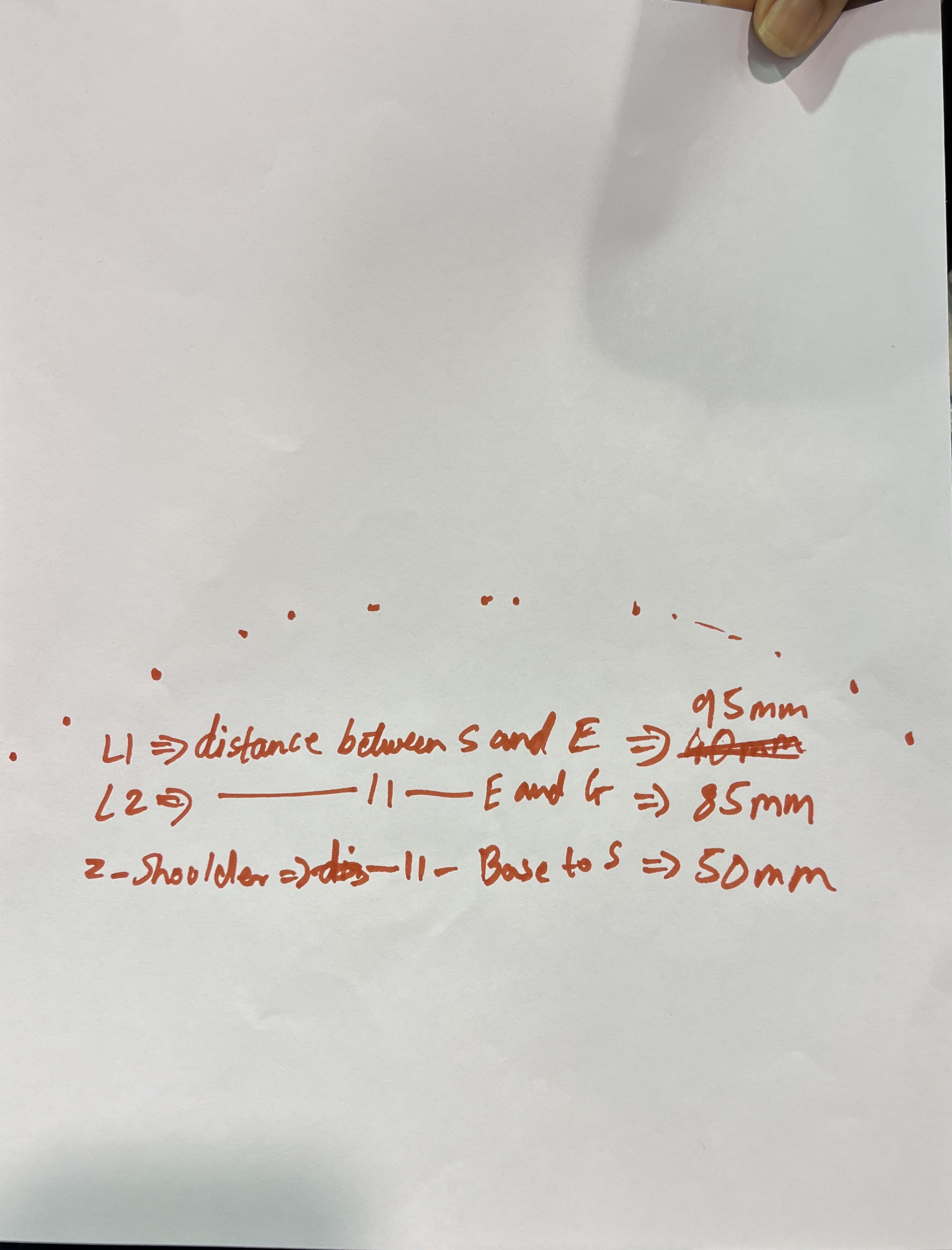
The planning code works in real-world millimetres on the paper. For each point on the path, it uses inverse kinematics(based on our measured arm lengths) to work out the angle for each joint, adjusts for each servo's individual calibration, and sends the angles to the ESP32 over a USB serial connection as a short text message.
We designed a simple set of commands:
- Move (B/S/E/G): set the base, shoulder, elbow and gripper angles. The move's duration is calculated automatically from whichever joint has the farthest to go.
- Timed move (T): the same, but with a set duration, for steady, evenly paced tracing.
- Home (H) and Stop (X): return to a safe position, or freeze in place.
The ESP32 moves each servo smoothly to its new angle, updating about 50 times a second, and only replies "done" once the move is actually finished. That means the planning code never has to guess how long a move takes: it just waits for the confirmation and sends the next one. If anything goes wrong, the arm goes to a safe "park" position (claw open, pen lifted, home) instead of freezing mid-move.
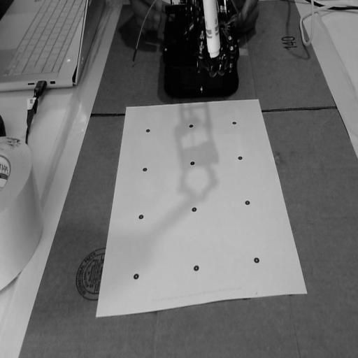
We also started with a different approach, fitting servo angles by moving the arm onto all 12 calibration dots by hand. Once we'd measured the arm's real lengths, we switched to direct inverse kinematics, which we verified against 500 random target points with zero error.
-
Plan Once, Then Move
42 minutes ago • 0 commentsWe realised our first design was ambitious. While tracing, the arm would check the camera every ~20 mm, and if something new had blocked the path, it would re-plan just the remaining route and keep going. We built it and it worked in testing, but the more we thought about the actual challenge, the more we questioned whether we needed it.
The organisers clarified that during the demo, the line and obstacle are placed before the run starts and stay put. With a still scene, watching the camera mid-trace adds extra steps, extra processing and extra ways for something to go wrong, with no real benefit.
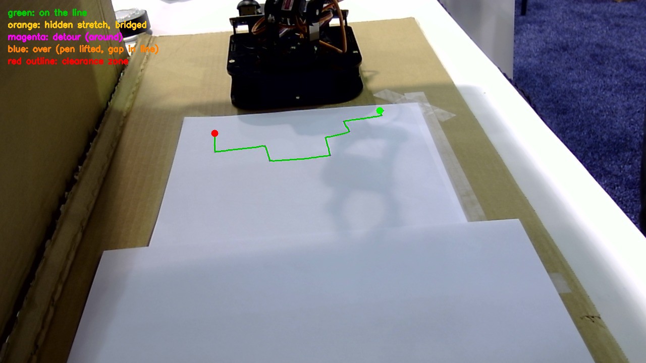
So we simplified. Now the arm takes one look at the scene and plans everything up front:
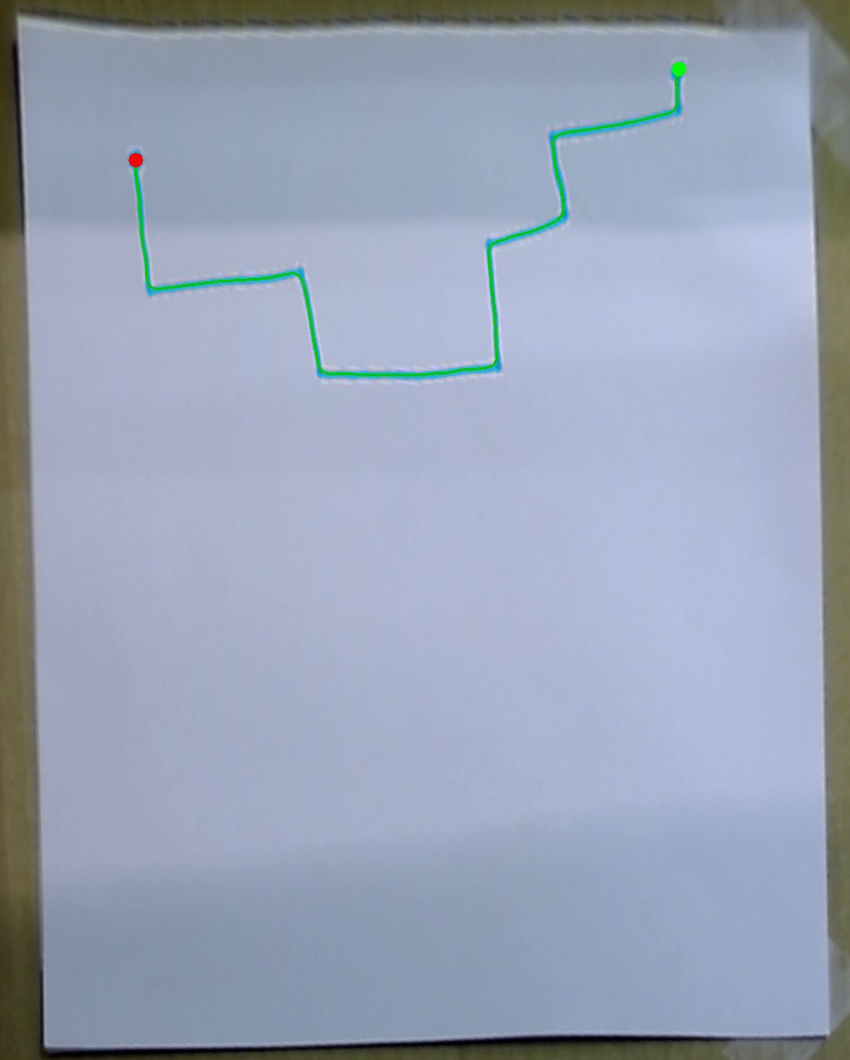
- Finds the marker, the line and the obstacle in a single camera frame. The arm is recognised too, so it's never mistaken for an obstacle.
- Plans the line, including any detour around the obstacle.
- Stitches everything into one complete route: marker → start of the line → along the line → end of the line → back to the marker.
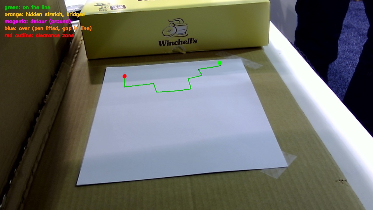
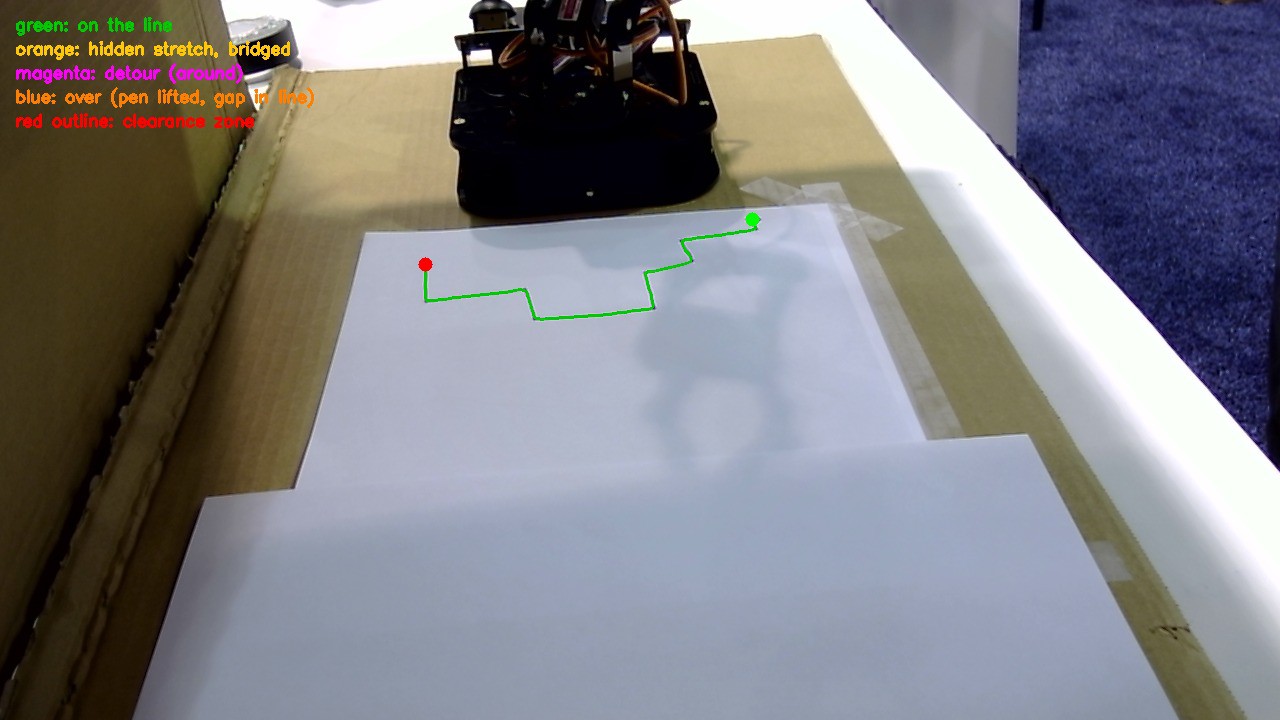
- Saves the full plan to a file, with every point labelled as drawing, detour, lift-over or travel, plus an overlay image so we can check it before the arm moves.
Then the arm simply executes the plan from start to finish. Sometimes the best engineering decision is knowing what to take out!
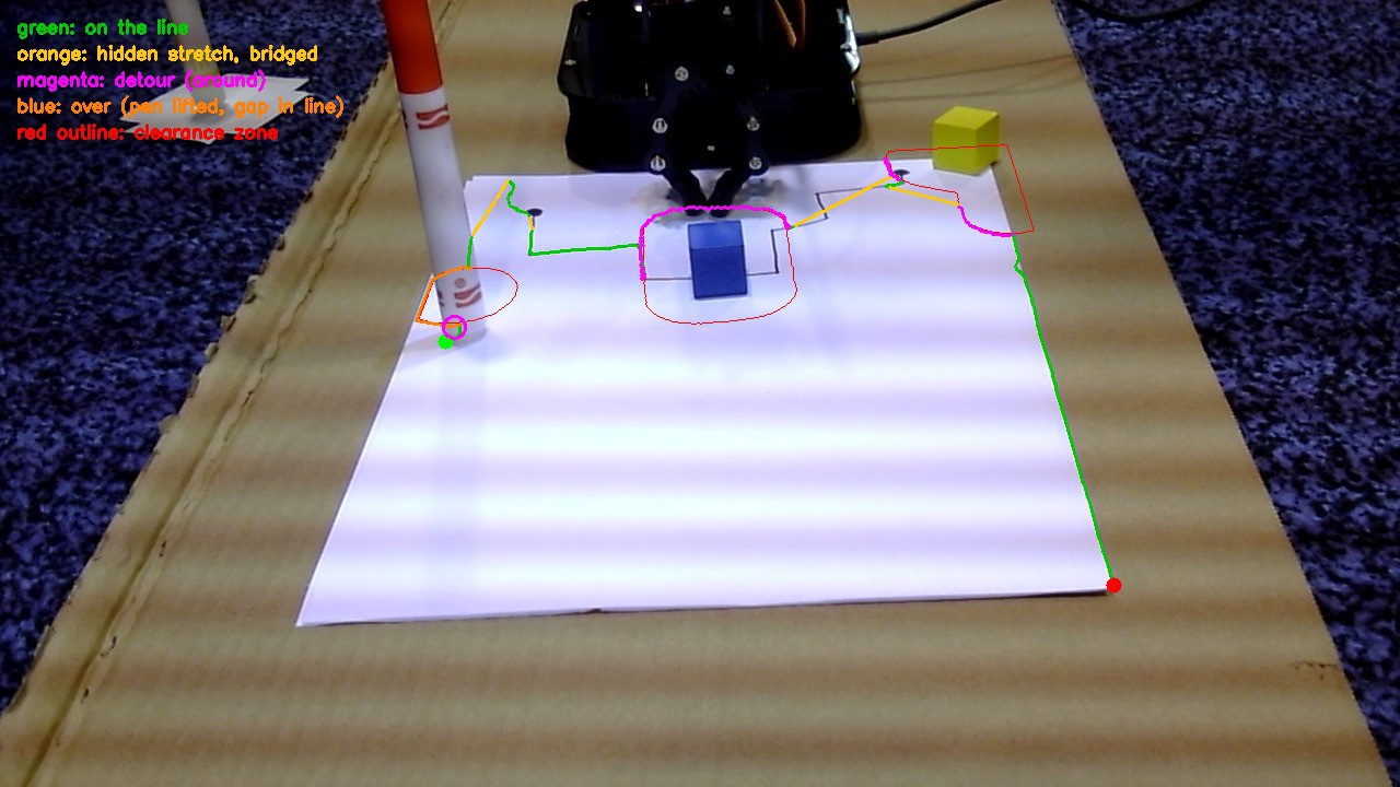
The full planned route overlaid on the camera view before the arm moves.
![]()
-
Around First, Over as a Last Resort
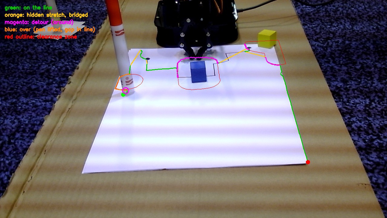
an hour ago • 0 commentsWhen the arm meets an obstacle on the line, it has three options, and it tries them in order:
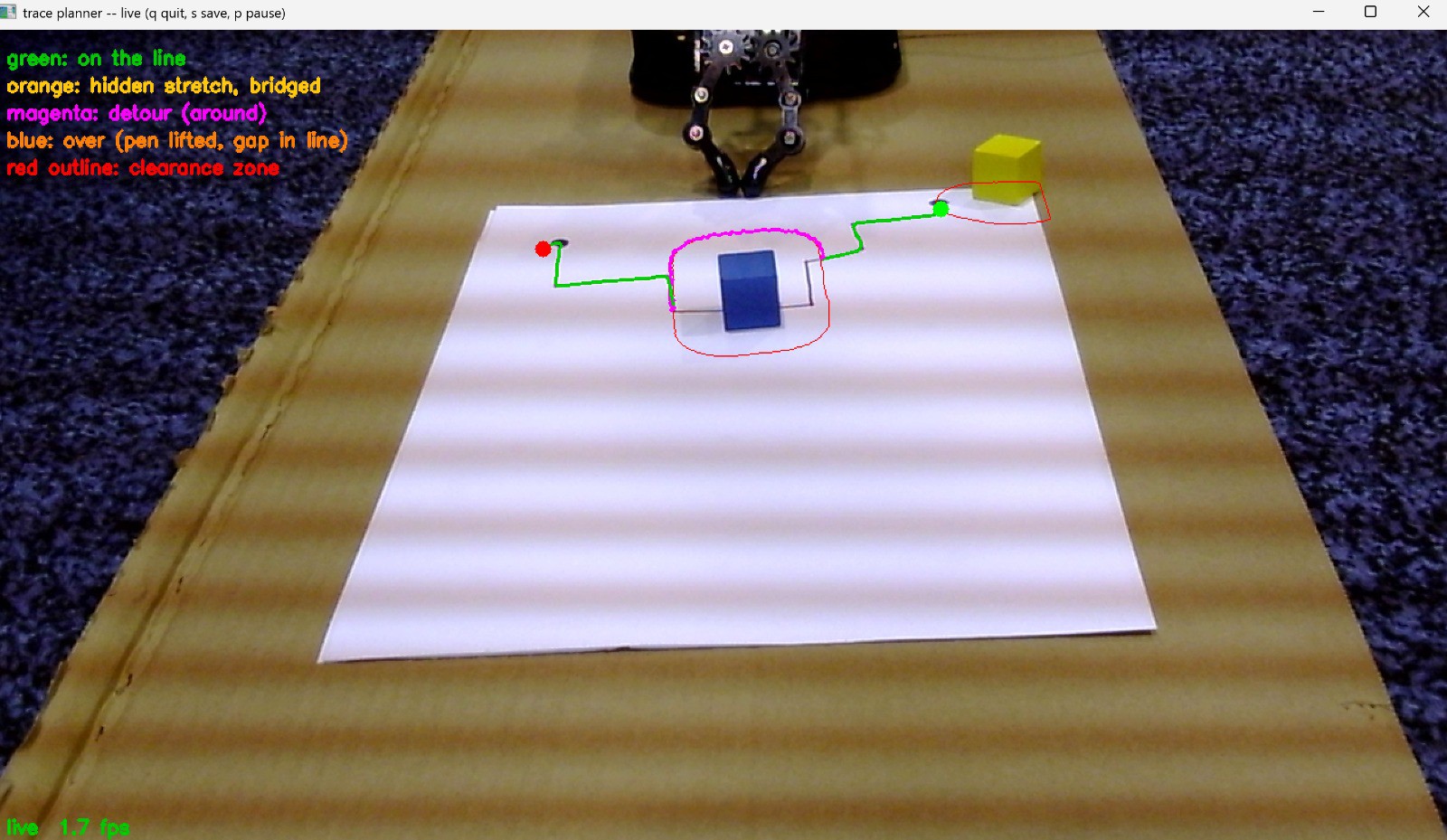
- Go around (edge walk). The arm follows the edge of a safety zone drawn around the obstacle until it can rejoin the line on the other side. It's fast (about 1 ms to plan in our tests) and works well for a single object.
- Search for a route (A*). If walking around the edge would take the pen off the paper, a grid search finds another way around. It's slower (about 2.8 seconds on the same test), so it's only used as a backup.
- Lift over it. If there's no way around at all, the arm lifts the pen above the obstacle and puts it back down on the other side, leaving a small gap in the line. The arm never drags the pen through an obstacle.
Getting this right took a few rounds of bug hunting. We found that the A* search failed completely whenever the starting point sat inside an obstacle's safety zone. We also found that smoothing the final path could nudge it a fraction of a millimetre into the safety zone near sharp corners (up to about 0.45 mm). We fixed both, and added a final check that pushes any stray point back out. Our tests went from 7 safety-zone violations to 0, and we added a special case for when the obstacle covers the entire rest of the path, where the arm simply goes over.
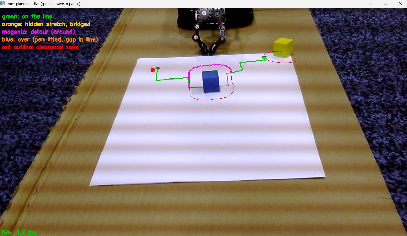
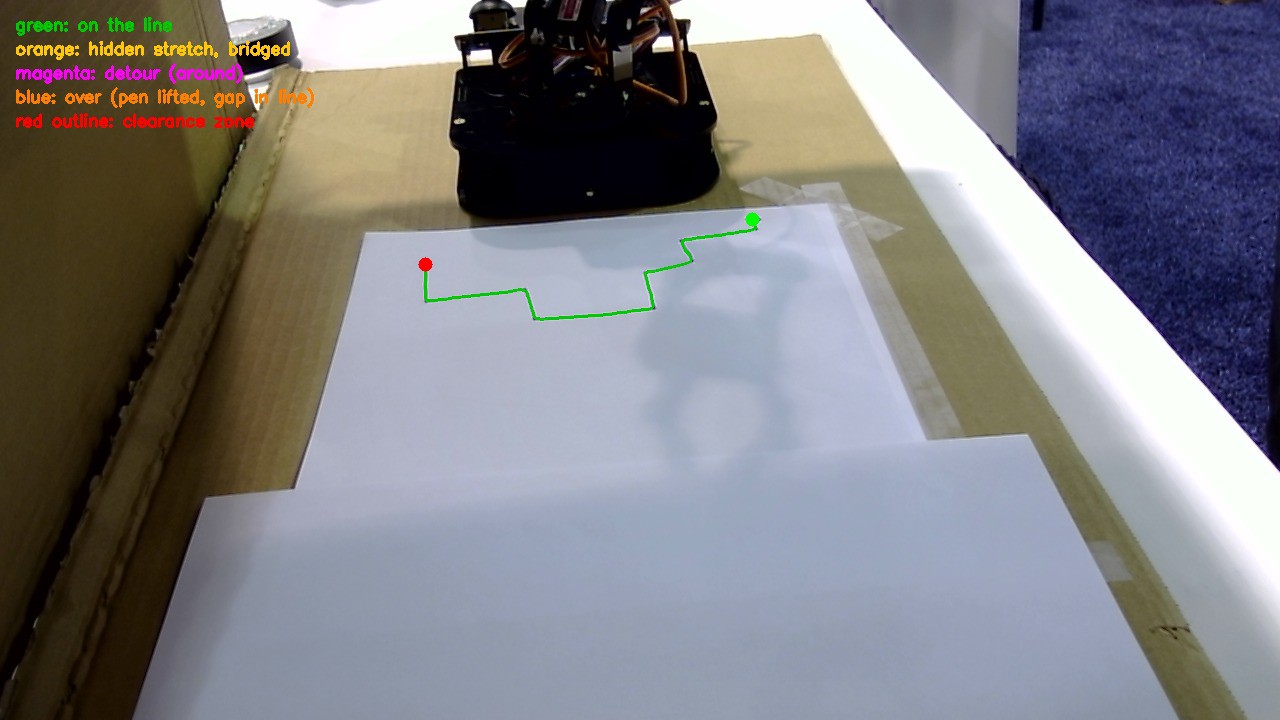
The path planner's colour legend: green = on the line, magenta = detour around, blue = lifted over, red outline = safety clearance zone.
![]()
-
The Black Webcam Issue
an hour ago • 0 commentsNot every problem is about algorithms. Sometimes the camera just won't cooperate. While testing on a laptop, our C270 webcam started causing trouble in ways we didn't expect.
First, it kept changing its device number. The same camera would show up as camera 1, then silently move to camera 0, with no error and no warning. The wrong camera would open, and every position the system calculated would be wrong. We tried identifying the camera by name from the system's device list, but that list changed order within seconds. We tried its "unique ID" too, but that turned out to change depending on which USB port it was plugged into.
In the end, we went with the most reliable test of all: look at what each camera actually sees. We saved a snapshot from every camera index and checked them by eye. One showed our desk setup, one was the laptop's selfie camera, and one showed only black.
That black frame was our next mystery. The camera returned a completely black image every time, byte-for-byte identical. We ruled out other apps holding the camera, then wrote a diagnostic that tries different video formats and resolutions and prints each frame's brightness values, so we could tell a dead feed from a dark room.
We also learned that the paper needs to be kept away from anything else bright in the camera's view. Once, a monitor in the background merged with the paper, and the software couldn't find the page's edges.
Lesson learned: when hardware misbehaves, check what it's actually doing, and don't trust assumptions about what it should be doing.
-
Colour vs Greyscale: We Tested Both
an hour ago • 0 commentsOnce we had our labelled dataset, we faced a question: should the model learn from colour images or greyscale ones? Greyscale models can be more robust to lighting changes, while colour gives the model more information to work with. Instead of guessing, we trained both.
Our first model, trained on 410 colour images, scored a mAP50 of 0.982. The greyscale version came in at 0.964, which was close enough that neither was a clear winner. We even built a version that automatically switched between the two models depending on the camera feed. After testing both live on the webcam, though, we decided that running two models added complexity without a real benefit, so we went with colour.
![]()
Then we pushed further. The judges might pick a different Crayola marker than the one we practised with, so we added 124 new images of markers in different colours, for 534 in total. The score dipped slightly to 0.962, but that was expected: the model was now learning what any marker looks like, not just one specific colour. On real footage it spotted the marker in 18 of 21 frames, and the misses were mostly frames where the marker hadn't come into view yet.
Finally, we trained a combined model that recognises both the marker and the robot arm itself (765 images), which reached a precision of 0.989 and a mAP50 of 0.985. Knowing where the arm is means the system never mistakes its own gripper for an obstacle.
![]()
-
Finding the Marker
an hour ago • 0 commentsDetecting the marker is only half the job: the arm also needs to know exactly where it is on the table. Our script
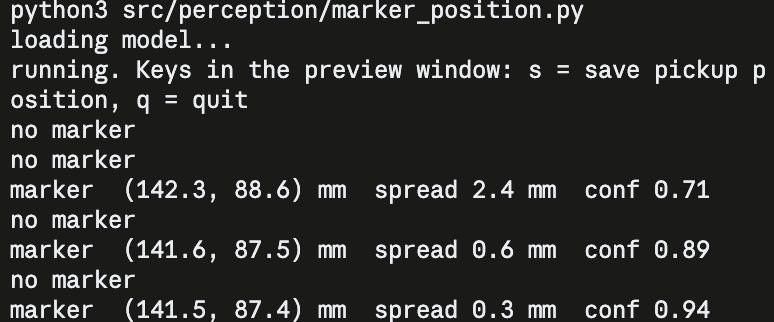
marker_position.pyhandles this step. It loads our trained detection model, watches the live camera feed and converts each detection into a real-world position in millimetres that the arm can reach for. For every frame, it reports the marker's coordinates, the spread (how much the position varies across recent readings, so lower means steadier) and the model's confidence that it's looking at a marker.
In this test, the readings settle quickly. As the detection locks on, the confidence rises and the spread drops from 2.4 mm to just 0.3 mm, so the marker's position holds steady at about (141.5, 87.4) mm. The occasional "no marker" lines are frames where the model wasn't sure enough to report a detection, and the script simply skips them. Once the reading is stable, pressing s saves it as the pickup position. That's the "remembered start location" the arm uses to put the marker back at the end of each run.
Live output from marker_position.py: as the model locks onto the marker, the confidence climbs from 0.71 to 0.94 and the position settles to within 0.3 mm.
![]()
EWNA Hackathon Team 1 (Team Marker My Words)
A 4-DOF arm on an Arduino UNO Q that sees a hand-drawn line, picks up a marker, traces it, dodges obstacles live, and puts the marker back.