 mircemk

Audio equalizer (EQ) is an electronic device that allows control over the strength of different frequencies in the audio signal. Generally, there are two types of equalizers, Graphic or standard, and Parametric Equalizer. The main difference between these types is the degree of control over the sound: the graphic EQ gives you control only over the strength of the previously fixed frequency, while the parametric one gives you complete freedom to choose which frequency you want to change and how wide it affects the filter.
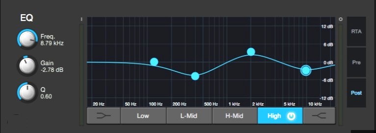
However, a parametric equalizer is much more complex to manufacture, much more expensive, and is therefore most often used in professional studios.
This time I will present you a way to build a budget-friendly and relatively simple stereo parametric equalizer using an ESP32 microcontroller and a WM8960 Stereo CODEC (Coder-Decoder) Audio Module. The settings can be visually monitored on a Color display, which gives another professional feature to this advanced audio device.
This project is sponsored by PCBWay. From September 1, 2026, to January 24, 2027, PCBWay is hosting its 9th Project Design Contest. You can enter in five different categories: Edge AI & IoT, Robotics, Power, Open Theme, and Mechanical. Valuable prizes—including cash, coupons, and single-board computers—await the winners, while every participant will receive a Raspberry Pi Pico. Don't miss this opportunity to share your work and win great prizes. Make PCBWayyour first choice!

First of all, I would like to present the function of the equalizer in the simplest way possible, without going into technical details. At the input of the audio system, we bring so-called pink noise (that is, all audible frequencies together, with equal intensity), which is graphically represented by a straight line in the entire range.
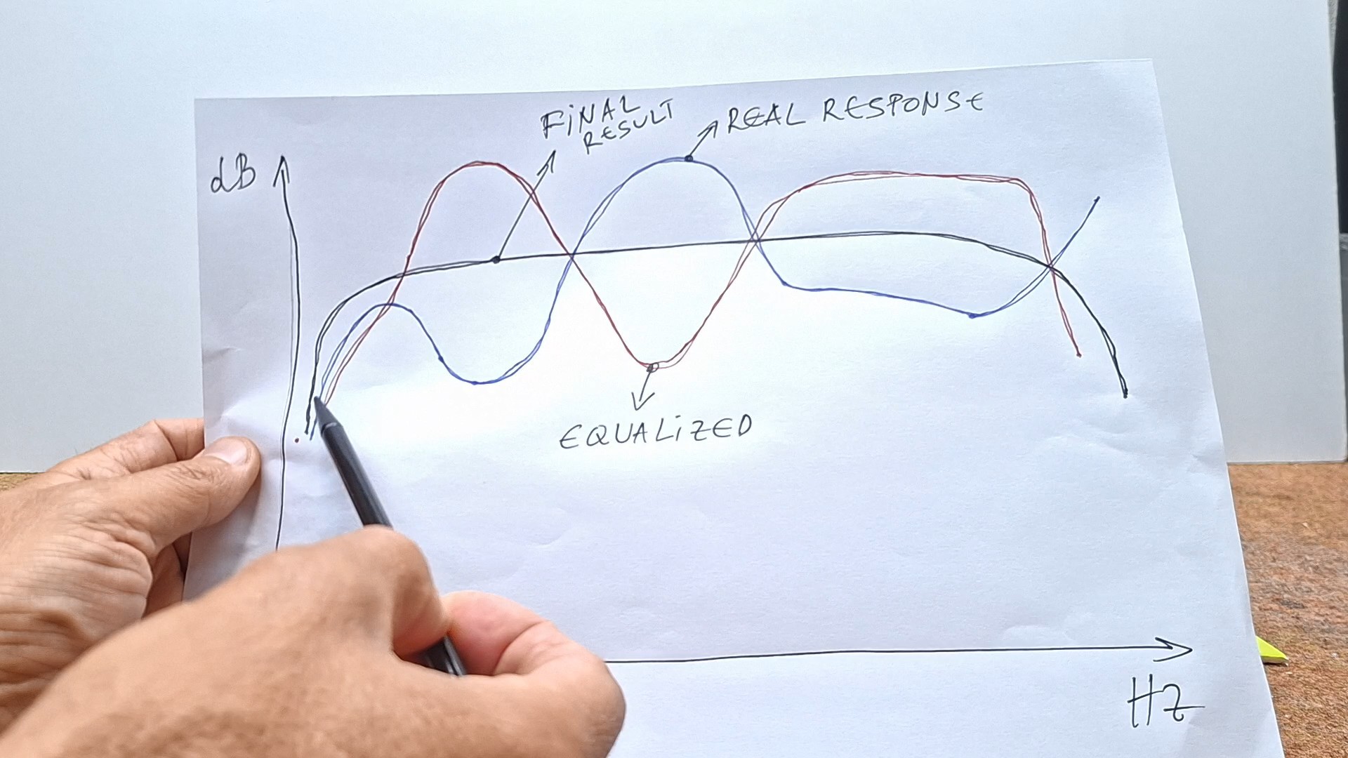
Now, if we place a microphone with a spectrum analyzer at the place where we should hear music, theoretically we should get the same almost straight line on the analyzer as on the system's input. However, most often, due to the nonlinear characteristics of the speakers, but also the geometry of the room, at the place intended for listening, to the spectrum analyzer we get a curved line, for example with a shape like in the picture (the red line). Certain frequencies are amplified, and others are attenuated. To correct this, we need to "draw" a mirror curve of the original with the equalizer (blue line). Thus, the resulting curve at the listening position would be approximately flat, which is the ultimate goal for quality Hi-Fi listening. This previously mentioned symmetrical mirror curve can be approximately adjusted with a Graphic Equalizer, and ideally with a Parametric Equalizer.
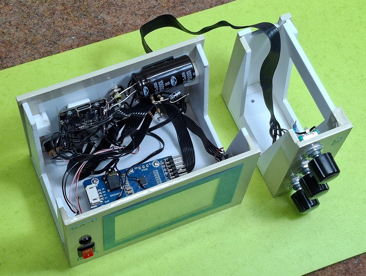
As I mentioned earlier, this device contains several components.
- ESP32 microcontroller board Dev1 30 pin
- WM8960 Audio Module
- ILI9341 320x240 LCD Display
- Rotary encoders
- And a few resistors
However, on this particular board, the 3.5 mm EARPHONE connector on this board is Stereo headphone output + microphone input. On the other channel there is an onboard MEMS microphone. So it is intended for stereo microphone inputs, and we need Line In inputs. With a small hardware modification of the board, we can get these inputs. It is presented in the pictures below.
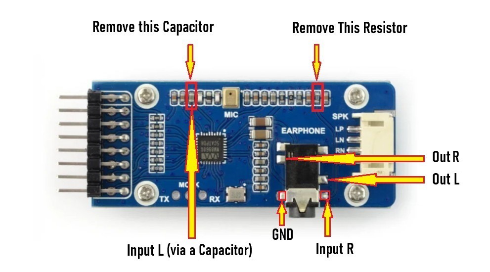
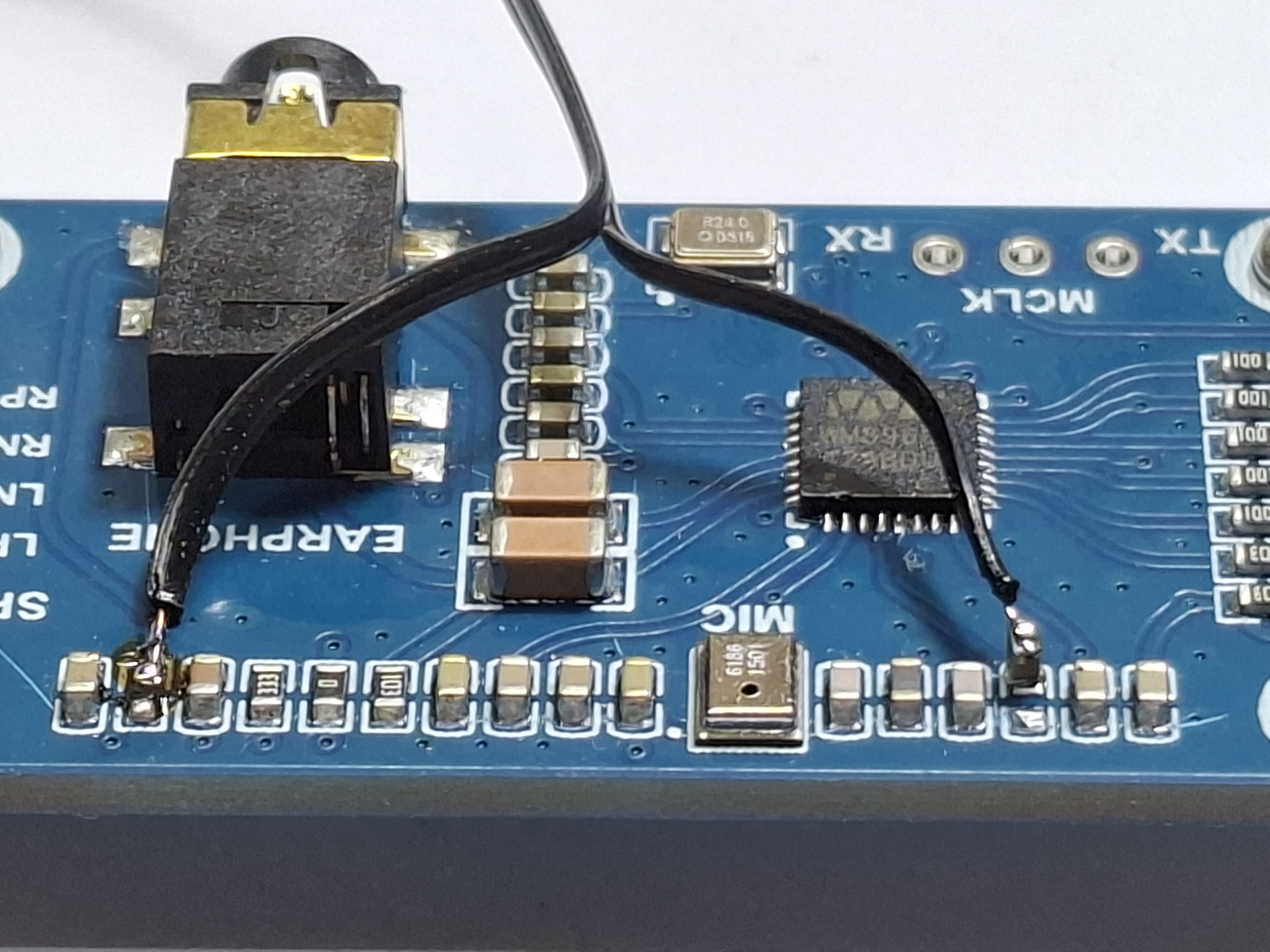
We need to remove the 2k2 smd resistor, and then one input is directly on the connector. As for the other input where the MEMS microphone is originally connected, the indicated capacitor should be unsoldered and only one contact should be soldered directly to the PCB as in the picture. The free contact from the capacitor is the other input. Then, directly on the RCA connectors we form a voltage divider with two resistors as shown in the schematic.
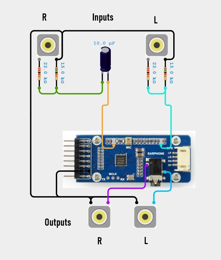
With this, the hardware part of modifying the audio board is complete.
As you can see, the device I built is a tangle of wires, but this is merely a test unit intended to demonstrate functionality. The...

 Matt
Matt
 Flo
Flo