Douglas Miller
-
Firmware uploaded.
07/26/2017 at 00:07 • 0 commentsI finally have the firmware for the machine cleaned up enough (I hope!) and uploaded. You can find it in the projects file list.
I also stuck in the beginnings of an operations manual. It has the list of commands to run the machine in it. It's in the same ZIP file as the firmware. The operations manual is a bit lean, but I'll be adding to it as time goes on.
-
Digging my way through the documentation. Uploaded files.
07/19/2017 at 16:29 • 0 commentsAfter a few frustrating weeks I've finally got the build files ready and uploaded.
You can find them here or on the projects github page. They include a BOM and an assembly manual as well as all the STLs and DXFs needed. As a bonus you can get the laser cut files in either DXF or SVG formats, your choice. Personally, I'm using the SVG's. They seem to have come out cleaner than the DXF's. That's all because the original project was done using Corel Draw and 123D Design, and I was forced to move them over to Fusion 360. Not everything went smooth in the process, a product no doubt of my having no idea how Fusion 360 worked at the time. If you find anything that needs work in them PLEASE let me know and I'll try to get them fixed as fast as I can.
The Bill of Materials shows the cost to build one. It comes in at around $252 dollars. But that's buying everything new, and I'm sure you'll have some of it hidden in your shop somewhere. It also doesn't take into account the deals you can get online if you shop around. Some of that Ebay stuff is getting downright cheap. I tried to stay at the very top of what I could get things locally for, and the small town I'm in doesn't exactly have many places to shop. All of that should be good news as far as you building one cheaper.
A good part of the cost is in just the electronics. The Arduino Uno + gShield alone = $74.99, or 30% of the total. Add in two steppers and the power supply = $120.00 total. That's getting real close to half (48%) of the entire cost of the machine just right there.
Yet to do: Operations manual and firmware.
The firmware will be first, and hopefully within a week or two. It works now, but there's a few bugs I want to fix. I really want to take the time to do a little rewrite of it and straighten a few things out, plus there's a section that's not even needed anymore but will take a bit of work to get rid of without making something screw up somewhere else.
I'm sure the assembly manual will need some editing. It all looks good to me this morning, but it's most likely a bunch of gobbledygook that even I won't be able to make sense of in a week. Lol. Such is life. If you don't understand something, let me know and I'll try to rewrite that part of it.
Basically, I'm saying this is like version .05 or something like that. So take that into account, if you would.
-
Laying yet more fibers.
05/24/2017 at 18:51 • 0 commentsMy last run went well enough, but it left me with a few questions, too.
For one thing, was the base plate not being charged effecting how the fibers were being laid down?
Another one is what's the difference in the fibers between the angled plates and the rotary cage?
To answer the first one I laid down a piece of aluminum foil between the angle pieces, and pinched the the foil under them to hold it in place. It was a lot simpler doing it that way than making another plate. The answer is: no difference at all. So that solves that.
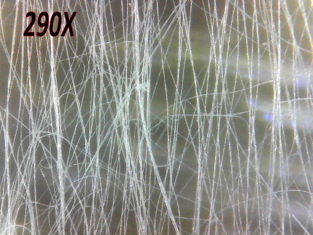
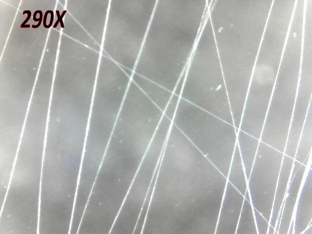
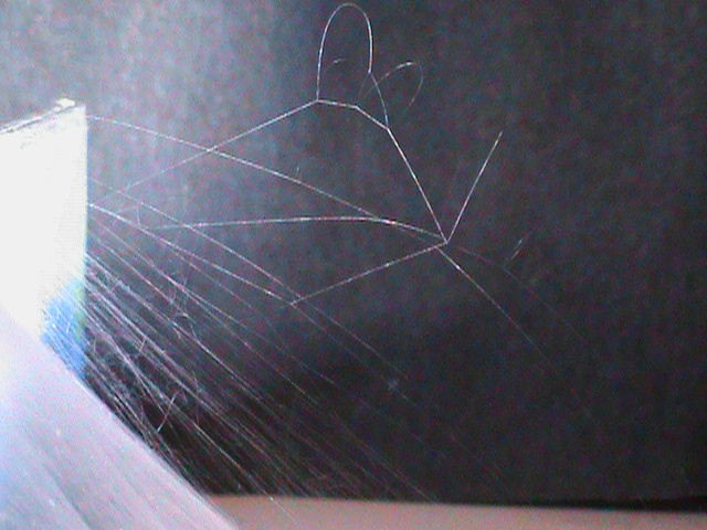
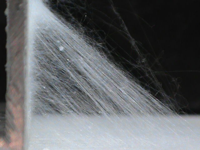
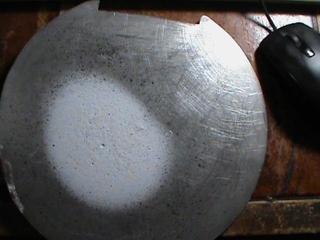
To answer the second question it was as easy as putting the rotary back in and running another batch. I kept the same mixture and feed rate from the above run so all that would be equal. The results rather surprised me. The rotary gave me noticeably smaller diameter fibers, but the angle plates ones, while larger, were better aligned parallel to each other. The rotary ones are also easier to collect.
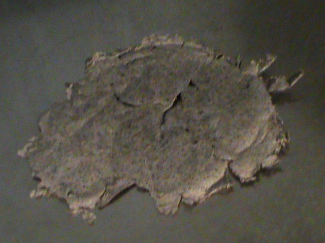
The first picture below is from the rotary and the second from the angle plates.
![]()
![]()
The machine is doing well and producing the same results with the same settings day after day. Pretty much if I'm careful to get the mixtures the same I'll get the same results every time. That's good to see.
So now it's back to sticking nanotubes in the mix and see what I can come up with. The main two goals of this is to strengthen the fibers considerably, and make more conductive fibers. All of this is basic stuff, I'm sure. But it's just something I need to figure out now before we go in even more directions later.
-
The pics I mentioned last night.
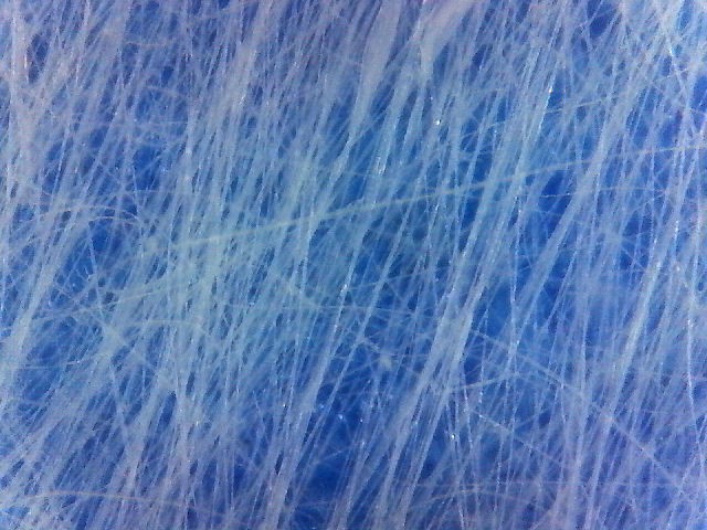
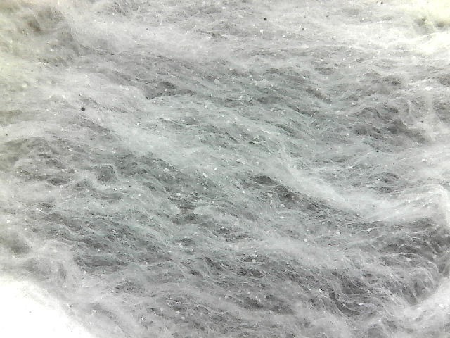
05/22/2017 at 15:41 • 0 commentsHere's the pics.
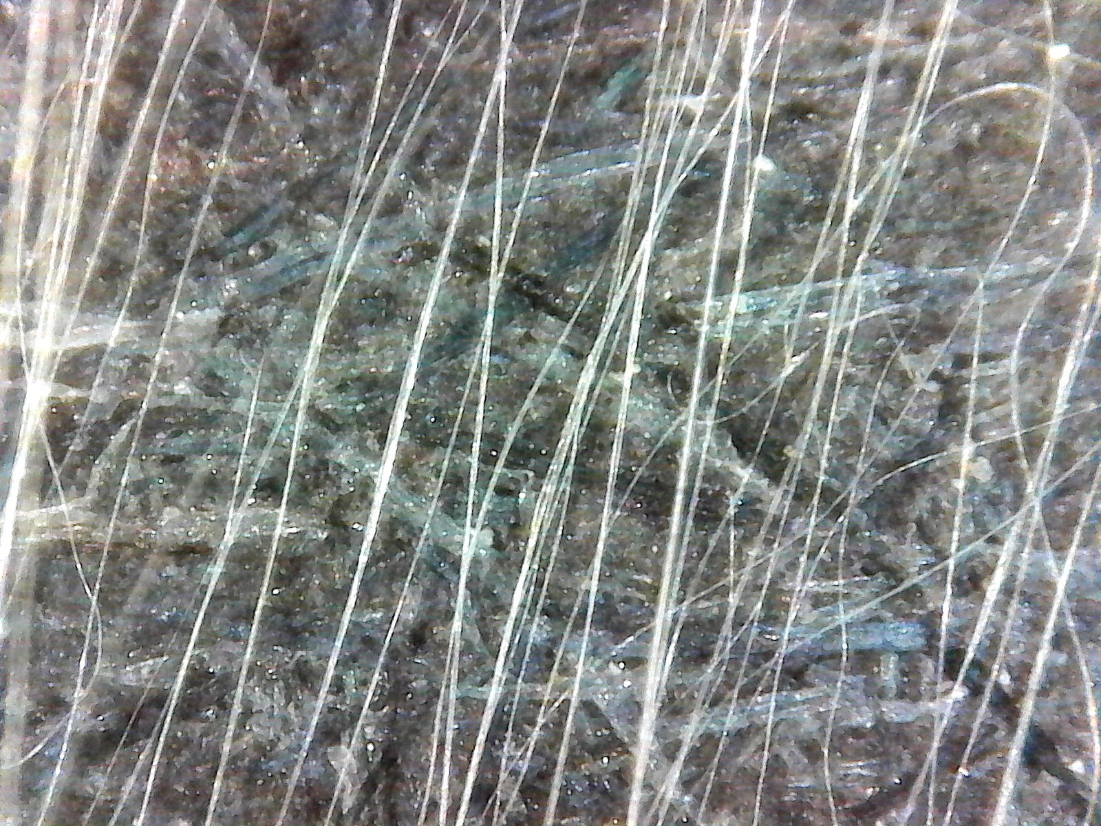
You can see they are mostly oriented parallel to each other. A few go against the grain, and I think a lot of them were done by me getting them onto a slide to put in the microscope.
![]()
![]()
![]()
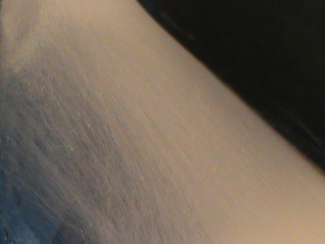
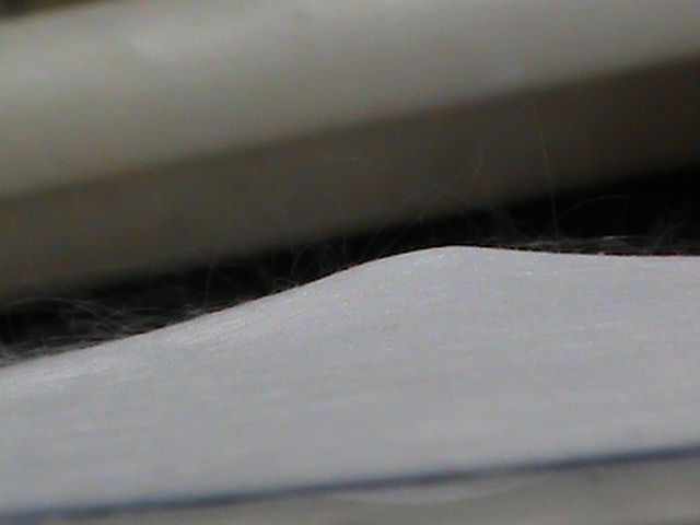
Electrostatic charge keeping them apart made this for a few minutes. As soon as the charge dissipated a bit they laid down:
![]()
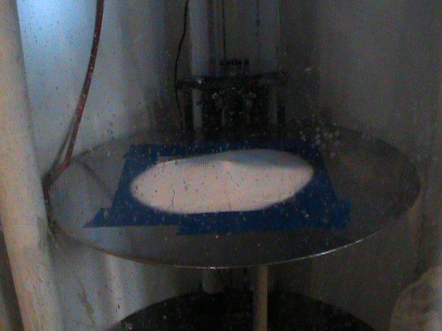
Here's what I meant when I said I ran it to a bit of excess. Didn't need even close to this amount, but it was running so well I didn't want to stop it. Lol. And anyway, it only took maybe 7 or 8 minutes to get all this. Once you're dialed in it cranks them right out. :D
![]()
-
Laying Fibers.
05/22/2017 at 00:38 • 0 commentsStorms were gone after noon today, so I got back to work.
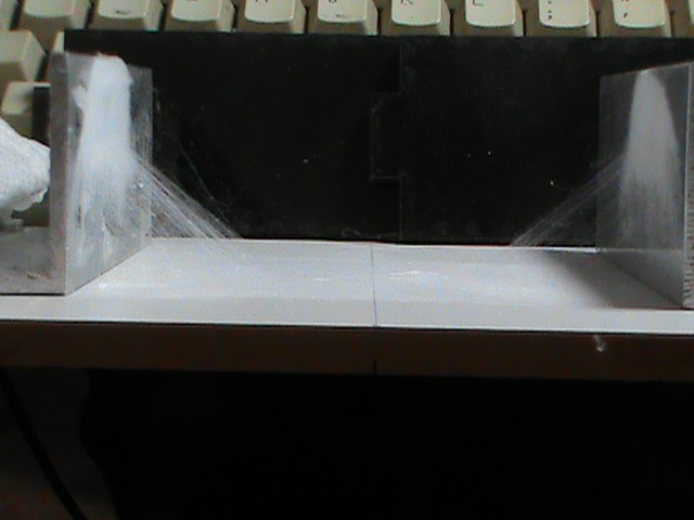
Picking up where I left off yesterday I fired it up with the plate with two aluminum angles on it. After twiddling with the settings a bit I started to pull real nice fibers. But they still weren't going from one angle to the other. It took me a bit to see why. Turns out some of they were going all the way across, but they sagged in the middle and touched in the center, where they stuck for good.
I figured that out by placing some blue painters tape sticky side up all across the table. By getting them to stick where they hit I could trace them all the way across. I don't remember them doing that a few weeks ago when I played with making parallel fibers. The only difference is last time the angles were just placed on the normal flat stainless steel plate and this time the plate is non-conductive. That's pure speculation at this point, but I guess there is one way it may make sense. That is the conductive plate is at the same electrical potential as the angles, where the this plate wouldn't be. I do know that the fibers hold the charge they are given as they are being pulled and tend to push each other away after they land.
Well, I'll explore that in a bit.
Right now I thought I'd show you some decent length fibers as they are being pulled and laid down. Check out this video:
Sorry about the light moving around so much. It's hard to get a flashlight to hit at just the right angle, and they are so thin they're hard to spot otherwise.
It lays them down at a pretty good rate, don't you think?
Oh, and that's real time, too. It tends to put some fibers down on one angle for a while, then switch to the other for a bit.
Anyway, it's been a long day and I have a Doctors appointment in the morning, so I'll get the pictures up for you in the morning. You'll see they are nicely parallel, which was the entire reason for doing it this way. Collecting them and keeping them parallel when they touch down in the center is a challenge, but nothing that can't be worked out.
-
Individual Fibers.
05/20/2017 at 23:18 • 0 commentsWith all the talk about unwoven mats of fibers and their benefits and drawbacks, I thought I'd show how we can make individual or oriented fibers just as easy. The goal was to make some of them conductive, but a bad thunderstorm interrupted me, and it stuck around almost all day. Nevertheless, I got part way there.
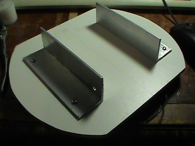
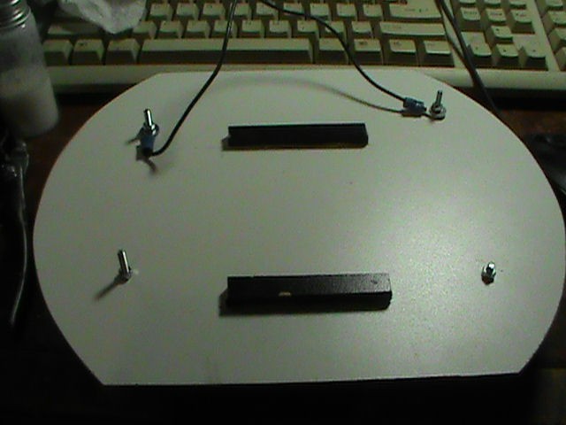
I started out cutting another table for the machine. This one has a non conductive surface. I bolted two aluminum angles on the top, spaced 100mm apart and centered side to side. On the bottom I gorilla glued two small wood strips to keep it centered in the machine. I left the mounting bolts a bit long to let me fasten the hV line to it, and a wire runs underneath to connect the two together electrically.
It wound up looking like this:
![]()
![]() The idea is the fibers will get pulled until it touches one of them, and when it breaks off from the needle the other end will land on the other one. I got close dialing it in before the storms hit but not close enough.
The idea is the fibers will get pulled until it touches one of them, and when it breaks off from the needle the other end will land on the other one. I got close dialing it in before the storms hit but not close enough.A lot of fibers were hitting too low on the face of the angles, and the other end landed on the table. I had a few do what I wanted, but not near enough.
This is what I got after about a five minute run:
![]()
![]() They ARE pretty much oriented parallel to each other, but not near long enough or in a good position to collect. I still think I would have had all the settings dialed in if I had been able to continue for a bit longer, but I guess I'll find out when I try again tomorrow.
They ARE pretty much oriented parallel to each other, but not near long enough or in a good position to collect. I still think I would have had all the settings dialed in if I had been able to continue for a bit longer, but I guess I'll find out when I try again tomorrow.The reason this works at all, I think, is because the fibers are still charged after they hit, and tend to try to avoid each other, including the other end of itself. So the other end whips around until it finds a different landing spot.
I collected what I could and this is what they looked like under the scope:
![]() I'm surprises I harvested them without messing them up more than that.
I'm surprises I harvested them without messing them up more than that.So, yes, we can get individual fibers or mats where they are all running parallel. Hopefully I'll be able to avoid close lightening strikes tomorrow and get longer and straighter ones. Time will tell...
As far as settings getting as far as I did, the plate was set at 100mm from the needle, the voltage was 19kV and it was a 15% ABS/85 solvent mix, by weight.
I'm thinking about taping off part of those aluminum angles to force the fibers where I want them. If I tape off too much I might lessen the voltage field too much, I don't know. Something to try tomorrow... :)
-
Desalination of salt water.
05/13/2017 at 16:31 • 0 commentsI've gotten a few requests lately about using this to desalinate saltwater. In my many travels around the web I ran into this the other day, so I thought I'd share. It's talking about a paper just published this year, and it may point to something we want to try.
I found the entire paper and I'm still going through it to see what we can glean from it, but it looks promising so far.
I'll add the link to Links bar of this project, but I thought I'd point it out for those who are interested in that sort of thing. I know I am! :)
-
Decided to play around today.
04/29/2017 at 23:40 • 0 commentsGoing through all the files, working on a BOM and the instruction manual finally got to me today. So I took a break from it all and had some fun.
The last couple of runs I've made have been a tad hard to get off the stainless steel plate. So I cut a square out of regular cooking aluminum foil and taped it down on the plate. Then I stuck that in the machine and made a thin layer of ABS fibers. I stopped it at that point and taped a really thin piece of bare copper wire across from one side to the other and taped that down. Another layer of ABS was then laid down across everything to finish it off.
This is NOT the conductive fibers I talk about now and then, but it's something to try anyway. I'm waiting until my next monthly stipend gets here so I can order some supplies to do the good conductive fibers, so I figured this will keep me happy until then.
In the end it came in about .02 mm thick.
To make sure I could find the center of the wire I made a loop in it and left it sticking up in the center of the plate. A small piece of tape kept the bare wire in the loop from getting irredeemably covered. As you can see in the pics it made a tent of the ABS as it got covered, but that turned out easy to get rid of with a sharp knife and a little bit of heat from a heat gun. It laid right down.
![]()
I like the way electrostatic keeps some of the loose fibers at the end sticking out. They go down with a quick shot from the heat gun.
![]()
Mildly surprised at home easy it came off the aluminum foil. Much better than the SS plate. Anyway, the foil could be used again if I cared to. It came off it that clean. Something to keep in mind.
![]()
So how did it turn out? Pretty good, if you ignore the hole I burned in it soldiering a LED to the wires in the center, only to find out the LED was no good. I took the LED back out and quit while I was ahead. Didn't really want to show it off with more holes in it, but then again I didn't want to show it with ANY holes at all, but that ship's sailed. I did a continuity check and the wires were fine. They were also well coated and I couldn't short them out when I balled up the mat. Yep, I could still ball it up and straighten it back out. That, of course, is great for wearables and stuff like that. Kind of a different take on a flexible circuit board, for that matter. You could make as many layers as you want, running wire's willynilly all over the place. Want a 28 layer flexible PCB board? No problem! Gotcha covered.
![]()
![]()
![]()
So what have I proved? Well, I can make water proof PCB boards, for one thing. Wearables has been done to death, but this brings in a lot more materials to it, so that's something. It also showed stopping a run, adding things and then restarting works just fine. A bit of heat and everything's good to go.
And, if nothing else, I got some more experience with the machine and had some fun. Can't beat that. Tomorrow I'm sure it will be back to manuals and parts lists, but the the machine's slowly teaching me what it can do, and it's fun to play with it and learn.
Now if only that monthly stipend would come early, I could really make it strut it's stuff. :)
-
Github files
04/28/2017 at 00:05 • 0 commentsWorking on getting the files for the new version onto github. Any questions about them, just ask. At the moment all I have is the DXF's and STL's uploaded. Build instructions and BOM will be uploaded as soon as they are ready.
-
Another run, some good and some bad.
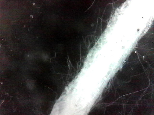
04/26/2017 at 00:07 • 0 commentsFirst, take a look at the photo below, before you watch this short video.
The photo shows what seems like one big fiber. But you see all those small fibers hanging off it's sides? Turns out that large fiber is just a collection of tiny ones. This happens when a long fiber forms but hangs on for a few seconds. Short fibers are continually formed and stick to it, and eventually forms what looks like a thick fiber but really isn't.
![]()
I wanted to point that out before you see the video because you can see it happening if you look close.
Also look real close at the material as it comes out of the emitter. You can see dark particles streaming into the center of the fiber. Those are carbon nanotubes I spiked the mixture with. The idea was to strengthen the material produced. And it worked.
Sort of, anyway.
Now watch the video, then I'll finish explaining:
I ran this mixture through the ultrasonic cleaner a few times to mix it up well. Which it did. The problem is the CNT's tend to stick together in clumps, and those clumps weren't broken up enough or simply reformed. I think what I need to do next time is add a small drop of mineral oil to CNT's to keep them from doing that. Stay tuned for how that turns out.
To make the mat stronger ideally I'd want the CNT's running the same direction as the fiber. If they're all mixed up and pointing wherever they feel like it it won't be as strong for a given amount of CNT's. That's the entire reason right there why you need to electrospin the stuff. The shear forces as they enter the Taylor cone gets them into that alignment. The clumps did that to a small degree, and the mat's stronger for it. But nowhere near where it would be had they not clumped up.
One other thing I'd like to note, and that is that with the CNT's in there it took a higher voltage to get them to pull like I wanted them to. Like 16 to 18 kV without and 24-32kV with them.
Okay, how about the mat being stronger? Yeah, it is. I made this one pretty thin and that plus the fact the CNT's were in it made it a real bear to get off the plate. I tore it up some doing that. This one is also water tight as long as you stay away from the holes I put in it. My bad.
I can fold it up like the past one, but it's no where near as flexible. It's pretty tough, actually, even more so when you factor in it's average thickness mics out to .01mm. I can't wait till I get to the part where I'm trying to make a quad frame out of ABS and CNT's!
![]()
![]()
Not very pretty, is it? A mat only it's daddy could love...
Again, the CNT's clumped up, and that very much shows in it's coloring.
I don't think I'll run another one this thin. Too hard to get off the plate. Really, what I need to do is try this on the six rod rotary and leave as much as possible hanging off in mid-air. At least then I might be able to get it off without tearing it up.
And speaking of the rotary, here's some of the fibers I ran yesterday on that rotary. Notice how the fibers mostly run in the same direction? Love it! That's going to make a big difference when I get back to making the fibers conductive.
![]()
One final note. Well, a tease, really. I took a few hours and ran a 'out there' type of thing, and got interesting results. But you'll have to wait to see what it was. I will say it involves electrospinning and 3D printing. I have some stuff to put together before I show it off, so you'll just have to have patience with me. Sorry. :P