Douglas Miller
-
A short-short video.
04/24/2017 at 23:07 • 0 comments -
Some days I'm my own worst enemy.
04/24/2017 at 14:55 • 0 commentsA lot going on the past few days.
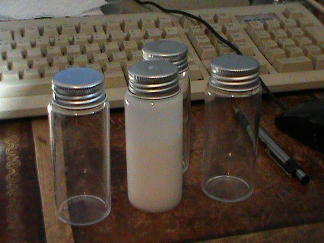
First off, I've pretty much nailed down the settings needed to reliably pull ABS. I don't worry about pulling >200mm long fibers anymore, thin as spider silk. Piece of cake. The secret was in the solvent/ABS ratio, specifically I had it too low. I'm having a lot better luck with it almost being to the point that the solvent is saturated with ABS and can't hold any more.
I was also running into areas where the material was thinned out too much, giving me much shorter fibers. I took care of that by sticking the bottle of the mix into a ultrasonic eyeglass cleaner for a bit to mix it up thoroughly. That made a big difference. I won't start a run with doing that from now on, even with a freshly mixed batch.
I picked up these small glass bottles at Hobby Lobby cheap, and they work great for preparing a batch and doing the ultrasonic mixing.
![]()
Producing mats is easy. After figuring out that ABS likes to be pulled with the positive lead on the plate and the negative on the emitter I can get the landing area much smaller and under control. No more stuff flying all over the place. The mats are easy to pull apart when they're done, so I'm doing a bit of post-processing on them. That consists of the highly technical feat of pointing a hot air gun at them to get the fibers to better fuse to each other. When that's done the mats hold together real well but are still flexible. You can ball them up in your hand without damaging them in the least. That'll be the form I want to form electrical circuits on.
So with all that worked out, it's time to do some real work, right? Well, this is where the 'own worst enemy' thing comes into it.
My next thing is to make conductive fibers, which I've already done to a degree. What I want now is to make the fibers in the mat line up side by side. To do that is what the rotary drum is for. As the fibers touch the drum the fibers are pulled down in the direction of the spinning drum. Cool, just what I need. For some reason when I put the drum in the machine I didn't think about the effects the reversed polarity would have. Well, it turns out when a drum charged to 20 kV gets within a couple of inches of a stepper motor, it'll find a way around the guards.
Yeah, I know, not too smart, right?
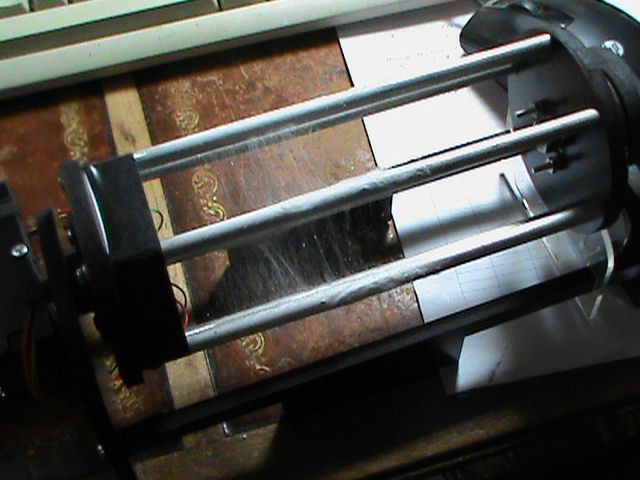
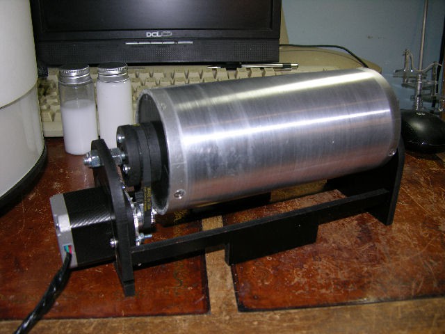
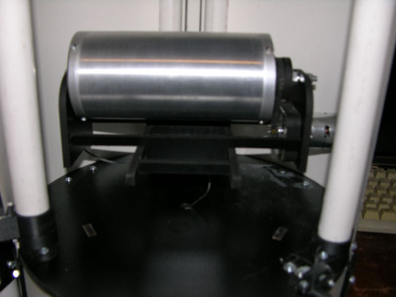
End result is the stepper driver board now has one dead output on it, so running a stepper is out on that channel. So I'm back to the DC motor I didn't really like before. I took a day and made another rotary, this one with six rods instead of a solid drum. The idea is the fibers will bridge the gap between the rods and be easy to collect. Turns out that idea works just find. It's fed by a separate power supply for now.
Here's what the new rotary looks like.
![]()
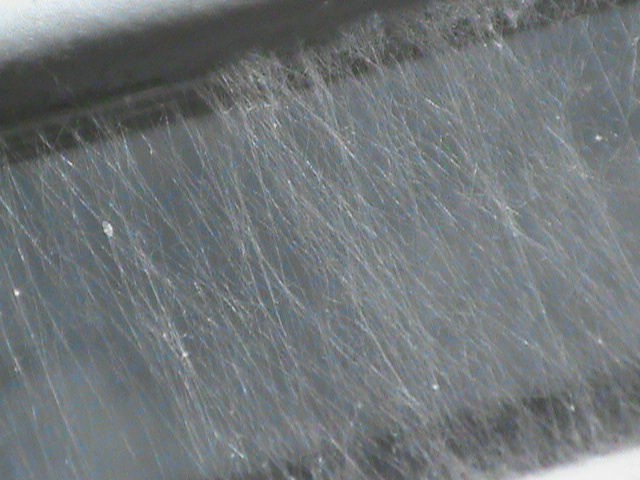
I did a quick five minute run with it and as you can see the fibers lined up nicely. Still can't go too high on the voltage, though. But it'll take up to about 20kV before giving me problems, and ABS pulls nicely at between 16 kV and 18 kV. So we're good there for now.
![]()
The theory is that when the mix is spiked to produce conductive fibers that the resistance will be less along the long axis than it will be side to side. That's because the conductive material will be aligned inside the fibers along it's long axis. That's the whole reason to use electrospinning to produce them.
I 'think' (believe it or not) that I'm about ready to put all this preliminary stuff behind me and make the good stuff. I know I've thought that before but this time I mean it. Lol. But things happen, and building, blowing circuits and rebuilding the rotary yet again is just part of the process. Or, at least, is it around here right now.
I'll have more for you soon.
-
Well, the glow didn't last after that last post...
04/16/2017 at 22:59 • 0 commentsI knew too much had gone right today. :P
I got ready to run a batch with the rotary a little bit ago. Turns out, not so much, at least not today.
As it turns out I can't run the rotary with the polarity reversed on the HV side. The current takes a short cut from the drum to the rotary motor, shutting everything down. At least it only gets the Arduino confused and didn't kill it. So there is that.
Back as soon as I do a bit of redesign on the rotary. I might as well go ahead and order a proper slip ring for it while I'm at it and get rid of the 'close enough for government' work I have now.
-
Well, now that that's sorted...
04/16/2017 at 20:49 • 0 commentsSpent the last few days making run after run, filling out page after page of charts of all the parameters as I went through to find the best setup to pull ABS. Got it about nailed down last night and hit it again today.
By noon I had it pulling dependable 200 mm to 210 mm long fibers, slimmer than spiders silk. And a very small spider at that!
Problem wasn't pulling them. The problem was where the darn things were going. I had a veritable forest of them at one point, with one end rooted on the plate and the other stuck to the top of the chamber. Yes, the chamber. What the heck? Why were they picking there to attach?
Check out the photos below.
This afternoon I played a hunch, and switched it up so the negative lead is on the emitter and the positive is on the plate. Guess what? It worked like a charm. The fibers now head straight for the plate instead of swirling all over the place. Before, as many if not most of the fibers stuck to the belt, the top of the chamber, and the chamber walls. Not any more.
Turns out ABS likes to be pulled in reverse, so to speak.
Why ABS and why all the attention on it?
Because I intend to make some more conductive ABS, that's why. I've already made some a few months back, but they were not in any form I could make use of, what with being sprayed all over the place. Now that I can get them to land where I want them I'm going to make a run on the rotary and get them all lined up running the same way. You'll see why when I get the results posted in a few days.
So that's where we're at. A VERY good day, I'd say.
Oh, one more point about switching the leads around. Before I had fibers all over the chamber. Now I ran a decent unwoven mat that was all in about a 75 mm diameter circle with the table set 200 mm away. There was very little spill over outside of that circle.
Yep, a very good day. :D
![]()
![]()
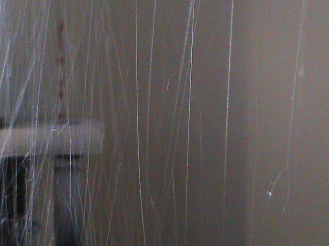
That last photo is of the fibers I'd managed to salvage from the 'forest' I had in the chamber. They weren't that messed up before I got them out of there. But you can still see they are not random but mostly run parallel to each other. I should also mention that's at about 270X magnification.![]()
-
Design your concept.
04/11/2017 at 19:27 • 0 commentsFor the first section of the contest, I think I pretty well have the design down pat. The machine is working well, to the current operators limits. Lol.
There is one change I'm considering making. Well, considering is probably not the word to use. I'm pretty darn sure I'm going to make the change. That is the manner in which the homing switch is done. It's fine for a flat table, but I'm working on accessories now, like the rotary, and that changes things a bit.
The different heights of the accessories means I'm not currently homing to an accurate measure of the space between the needle tip and the negative plate. Another problem I've had in the back of my mind is not everyone will use the same length needles I do.
So what I'm thinking, here during the design part of the contest, is to move the homing switch so it can take advantage of different accessories or needle lengths or whatever else comes along. The reason I didn't take a measurement directly from the needle itself is I don't want that switch and it's wiring anywhere around that high kV stuff, leading straight to the control board.
But now I think I have come up with a solution.
What I intend to do is put a switch up on top of the machine where it will get made if the needle and syringe are pushed up when homing the table. I don't think it will take all that much and all these problems go away, and we're assured we're working with the actual measurement between the need and the negative plate. So all that's good.
What I'm not sure about is if I'm taking a chance of bending the needle by letting the table give it a tap up. But I think I can avoid that. We'll see I guess.
At this moment this is the only change I'm considering making to the basic machine.
-
Slogging it through
04/08/2017 at 23:44 • 0 commentsWell, it's been a busy few days.
While not the results I wanted to show you by now, I can say I'm making progress. What I've been doing is going through all the variables involved and working on charting out the results. I'm concentrating on ABS right now simply for the reason I have a lot of it and the solvent is a lot better for my health than some of the others. Not saying healthy, mind you, just better.
Main thing to getting smaller fibers is solvent ratio, combined with feed rate and Hv level. Length is somewhat controllable by plate distance from emitter, but to a lesser degree. So for three days of work I think I've made progress getting a better feel for running it. I'd also like to add that the goal of making it get repeatable results has been met. The same settings are giving me the same results, every time. So that's a good thing.
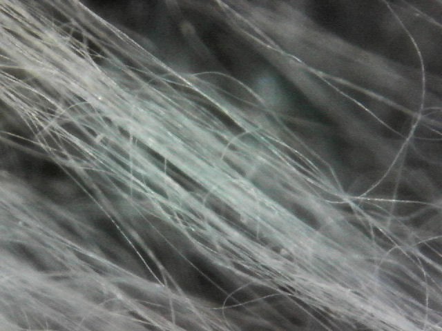
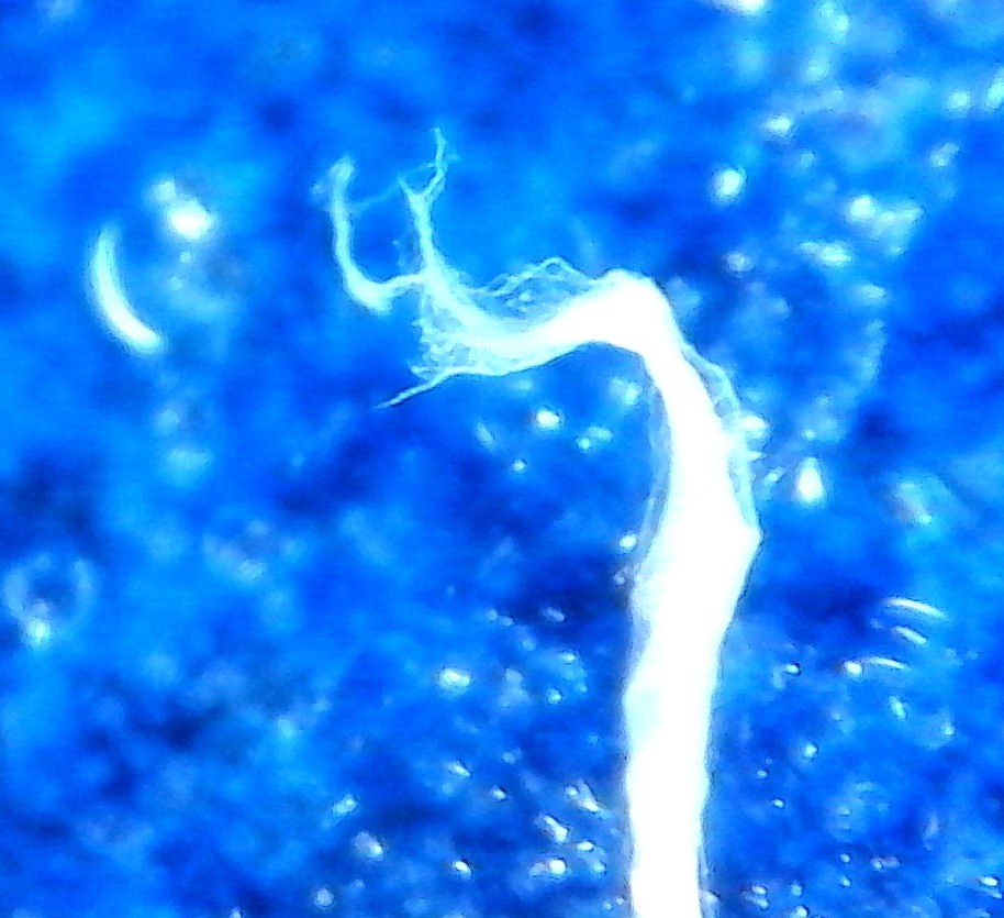
Here's a couple of pics of a fiber I found interesting. The white line is a fiber slightly smaller than a human hair. You can see where I found a section that shows that it's actually made up of a bunch of smaller fibers. Pretty cool for what I want to do.
The other pic is where I followed the fiber to it's end. It also shows the smaller fibers it's made up with.
The settings that made this fiber are real close to what I want for the main run I wanted to make this last week but got delayed. If it all works out I'll be showing you conductive ABS in the next few days. :)
![]()
![]()
Oh, and by the way, the blue background is because I used a piece of painters tape to collect the fiber. Seemed like a good way to pin the darn thing down, and the tape was handy.
-
Rotary: part two.
04/01/2017 at 21:45 • 0 commentsYeah, I went ahead and took a day to change the rotary. It needed done, and I need it, so it's not a wasted day at this point in the contest.
It's got a stepper on it now, and seems to work great. The speed is easy to set, if nothing else. But that's not all, of course. It's also smoother than the DC motor was and I'm guessing that's because the DC motor overheated so much. A geared motor may be even better yet, but I don't have one on hand and I need this thing, like, now.
I still need to come up with a better way to pass the negative line from the center axle to drum, what with the bearings not being conductive from the outer case to the inner hub, but that'll wait for a bit.
I really want to see if I can't blow your socks off with this next series of runs. So, this is what I've got to do it, so it will have to do.
Back in a few days with the results. I hope. Lol.
![]()
Oh, I might add one more thing: see those center tabs hanging down on the lower side pieces? Those fit into the cross pieces on the carriage and keep it centered and steady. All the accessories for the machine will have those, making swapping them out painless. I thought it was a nice touch.
-
New Carriage
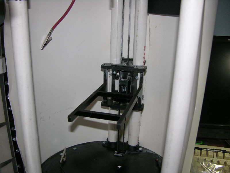
04/01/2017 at 18:54 • 0 commentsThe second big change in the machine is the Z axis carriage.
The old one worked fine, and was pretty much a one file 3D print. It didn't need any bearings, and was about as cheap as you can get to make.
But it had one drawback: I was worried about it handling heavier loads. For just a flat metal plate it's fine, but for my next trick I need a spinning drum, and with all that extra weight I was concerned I wouldn't be getting accurate movement.
So this is what I came up with. It lets me keep the PVC columns, which of course keep the metal around the chamber to a minimum. With 32kV in there that's a good thing.
This carriage does use bearings, eight of them. They sit at an angle to each of the two columns, and hold it in place with virtually no wiggle that I can detect. Side to side movement is pretty much nonexistent and movement is smooth. Just what I'm looking for.
It's mostly laser cut parts, so it's fast to make. Putting it together is a bit tricky, but doable.
So how does it handle the extra loads? Very well, thank you. I'm not going to say I won't be making improvements some time in the future, but this is fine for now. I put the rotary on it, and then tossed some extra stuff laying around on top, extra stepper motors and such, and it didn't care.
It looks huge in the chamber, at least compared to the old one, but I'm good with that for now. That's probably the first thing I would work on if and when I revisit it in the future.
Oh, well, okay, I just thought of something else I need to do to it. Those pieces sticking out and carrying the table? Well, one of them warped a bit and the table's leaning a fraction to the left. I think a quick change to those two pieces will stop that from happening. So maybe I better get those changed here shortly...
That's it, the second big change to the machine. It's a big improvement if you want to handle any thing heavier than a metal plate. And I do.
Well, back to work. I need to tweak a few things here and there, take a few pics of the rotary with it's new motor, and then make a few runs to show you what this is all about. I think you'll like it. :)
![]()
![]()
-
Rotating drum
03/30/2017 at 17:36 • 0 commentsA few days before I took the machine to MRRF2017 this past weekend I slapped together a rotating drum assembly. I've got a whole two and a half days in the thing. Not surprisingly, I don't like it. Lol.
So far I've mostly made unwoven mats. But for my next trick I'm going to have to get the fibers laid down side by side. There's a reason for that, which I'll go into as soon as the experiment is done.
The reason I don't like it is two fold: it's too fast, and it heats up too much. A side drawback, less serious, is it's not exactly quiet.
The motor and speed control are from an old cordless drill I took apart a while ago for a reason I don't remember. But hey, it's laying on the shelf and works, right? So I gave it a go. I modified the machine a bit to leave me a plug inside of the chamber, and a tossed together case for the speed control plugs into the back of the machine. So far so good.
But when I used it during a run even at the lowest consistent speed it was just too fast. It made it's own little wind storm over it's surface that flung fibers everywhere. Not good. Not good at all.
Add to that that both the motor and the controlled got pretty hot. That changed the conditions inside the chamber and made getting consistent sized fibers challenging. I had to keep adjusting things as the run went on. Since one of the main reasons to build a dedicated machine for electrospinning and not just using a cardboard box or something like that is to make things consistent, this thing just wasn't going to cut it.
To get it up and running before MRRF weekend I just used a spring inside that fastened onto the center shaft, which doesn't turn, and the inside surface of the drum, which does. That gave me my conductive path for the negative side of the hV. Which works. But it makes it loud to run. The day before the show I changed it over to a smaller spring inside of a 3D printed mount. The spring pushes on a metal ball bearing, which of course rides on the inside of the drum.
Still too loud.
So this thing will get redone in the near future. The basic idea is good, but I need to take a look at what motor I want to use for it that doesn't get so darn hot and runs too fast. A stepper might do the job, and would give me fine control over speed. But so might a geared DC motor, too. I have to admit having the motor speed under software control in enticing, so I'll tuck that into the final decision. One of the entire reasons for building this thing is to get consistent results run after run, so having the speed software controlled would be a plus.
If I decide to go with software control I need to consider the electronics, too. Only so many steppers can be hooked up to the board, so it might mean I need to switch that out. But a DC motor speed controller would be needed if I go that route, and while not all that expensive, they don't exactly give them away, either.
Either way I need to get it done. One of the things I intend to do here shortly will need this running right. If what I have in mind goes right I think you'll be impressed, even to the point of trying to find another way to get the same results without an electrospinner. I don't think you'll be able to find such a way, but it'll be interesting to see what ideas you throw out there.
![]()
-
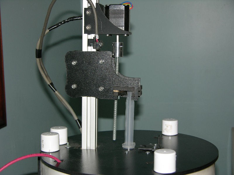
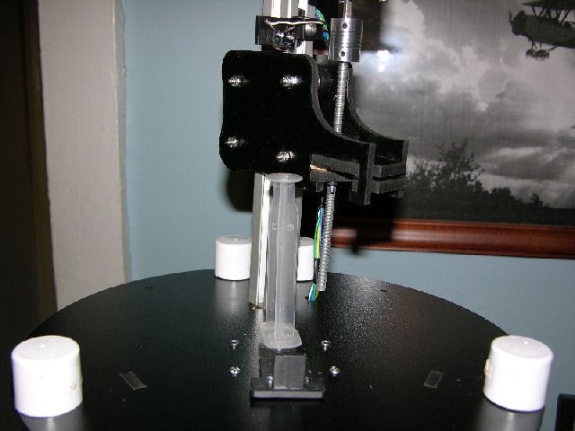
The new syringe mount.
03/30/2017 at 14:37 • 0 commentsBy far the biggest change in the machine was moving the syringe up on top. I did this for several reasons.
The first is that it is just more convenient. It's really easy this way to get a run started. Load up your syringe, drop it in the hole in the top of the machine, and go. Can't get much simpler.
With the syringe on the side we need to use tubing to deliver material to the emitter (needle). You have to take care to match the type of tubing to the solvent you are using, which means keeping a supply of different kinds of tubing on hand. Then you have make darn sure you grab the right one or you're likely to bust the tubing in the middle of a run.
It's also not all that convenient to run the tubing down into the machine, either.
Putting it up on top makes all of that go away. But it does have a few downsides. For one, it means I can no longer choose to run the emitter up and down and leave the plate at the bottom, as opposed to moving the plate and leaving the emitter at the top. That could, and I'm sure it will, effect future design decisions as far as accessories go. I'm willing to live with that.
One other down side is I really needed to make sure the wiring going to the top was shielded. It was fun running the shielded cable up inside the tubes, but it's worth it in the end.
As far as loading the syringe when it's up on top goes, I saw two ways to do it. One is to simply make the track the syringe rides on tall enough that running it all the way up leaves us room to drop the syringe in under it. That's not the way I decided to go. Instead I went with making the syringe mount swivel out of the way for loading/unloading. Taking advantage of the square shape of the extrusion I made it lift up and swing to the side, and when it's down it fits into the square hole and can't turn. That, naturally, would leave it able to get pushed up during a run and the screw pushes down on the syringe. That's solved by making a sliding plate on the bottom side that holds both the syringe itself in place and stops the syringe mount from lifting up. Works like a charm.
I love it this way. It takes the hassle out of starting a run. The hardest part of making a run now is mixing up the polymer and solvent in the right ratio, and anyone can do that.
That's the biggest change in the machine. It's not, however, the only change. I'll be getting to those shortly, so stay tuned in. :)
![]()
![]()