Nick
-
Oct 11, 2026: Error from a low gap
10/22/2026 at 04:34 • 0 commentsWith the printer running and no shielding, electrical-only noise was now within 2 µm (when not shaking my leg), now well below my accuracy floor. I could now calibrate my system. I built a fixture to calibrate against a Mitutoyo indicator.
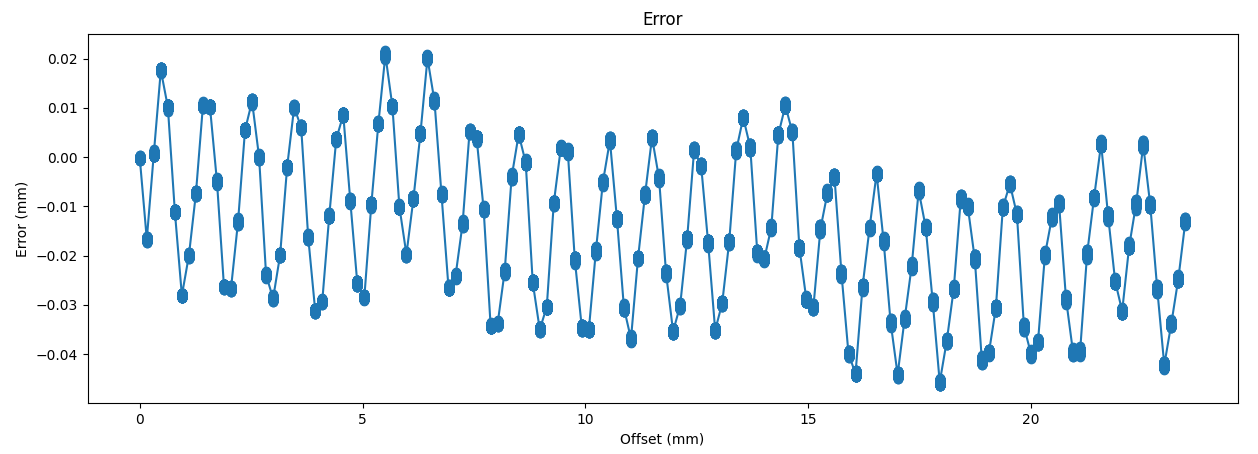
What remained was the systematic errors. I had a large error that repeated every emitter width, about 80 µm peak to peak.
- This is caused by the empty space between the emitters (5mil space between 20mil copper pads).
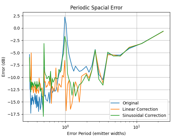
- The error has two slopes, not a sine shape. A piecewise-linear correction, worked out from theory with no tuning, removed it almost fully. A sine correction did worse.
![]()
The linear correction can be seen in terms of the spatial frequencies:
![]()
But this is very sensitive to scale distance. The boards were nearly touching in this test. I chose to add a controlled gap instead:
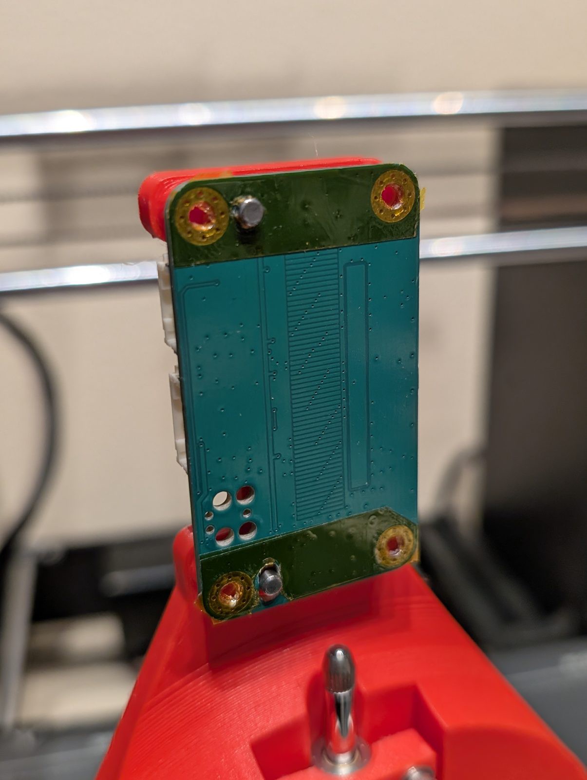
- Spacing the boards about 0.1 mm apart cuts the fringing error without any software correction. The tradeoff is a lower SNR (still a better accuracy, though).
- I tried a 3D-printed shim to set the gap. Two layers of Kapton tape were easier and more accurate.
![]()
-
Sep 16, 2026: Mechanical Noise Issues
10/22/2026 at 04:28 • 0 commentsAfter the new front end, a slow 10 to 20 Hz wobble was the largest noise left. I assumed it was aliased electrical noise.
- Changing the sample rate didn't move it, so it wasn't aliasing.
- The power supply showed nothing at that frequency.
- Low electrical frequency would cancel out due to the measurement algorithm. For example, 60 Hz cancelled below the white-noise floor.
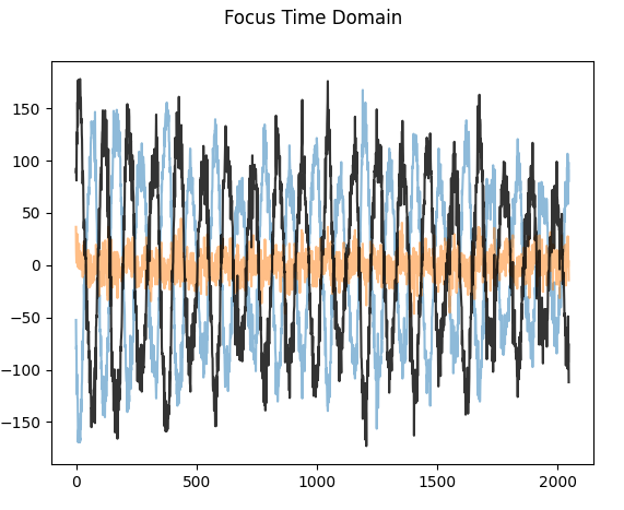
So aliasing was out. I was pretty lost on this one for a few days. It was intermittent and hard to catch. Finally I just plotted live raw position on my computer screen and sat there watching it. I sat there for a few minutes before shaking my leg.
It grew when I shook my leg. And it grew with how hard I shook. My dog chewing a bone was enough to show up. The printer was about 10 feet from us.
The sensor was measuring real motion! The printer frame rings at around 10 Hz, with harmonics at 20 and 30Hz. It moved around 4µm pk-pk. That resonance still shows up in my noise plots today since I have not built an improved mechanical test fixture yet.
The image below shows the oscillations in black (after cancellation). The vertical axis is ADC counts and the horizontal is milliseconds.
![]()
-
Sep 12, 2026: Analog Hardware Improvements
10/22/2026 at 04:21 • 0 commentsFor 1 µm resolution I worked out that I need 625 counts of signal for every count of noise. Sampling the raw RX spike would never get there. The raw signal is a short-lived, low impedance spike, so it's challenging to meaningfully filter. I weighed three options:
- Differential pickup pads. In theory they cancel noise, but I estimated only about 30% rejection in practice because these would receive different near-field noise magnitudes. I also couldn't find anyone using this method in practice, only theoretical early developments like patents.
- Switched capacitors. Good in simulation, but I would need 8~16 tightly matched capacitors.
- A charge integrator. This turns the short spike into a held step whose height is set by a capacitor ratio. The ADC can then oversample it over a long window or an analog filter can act on it cleanly.
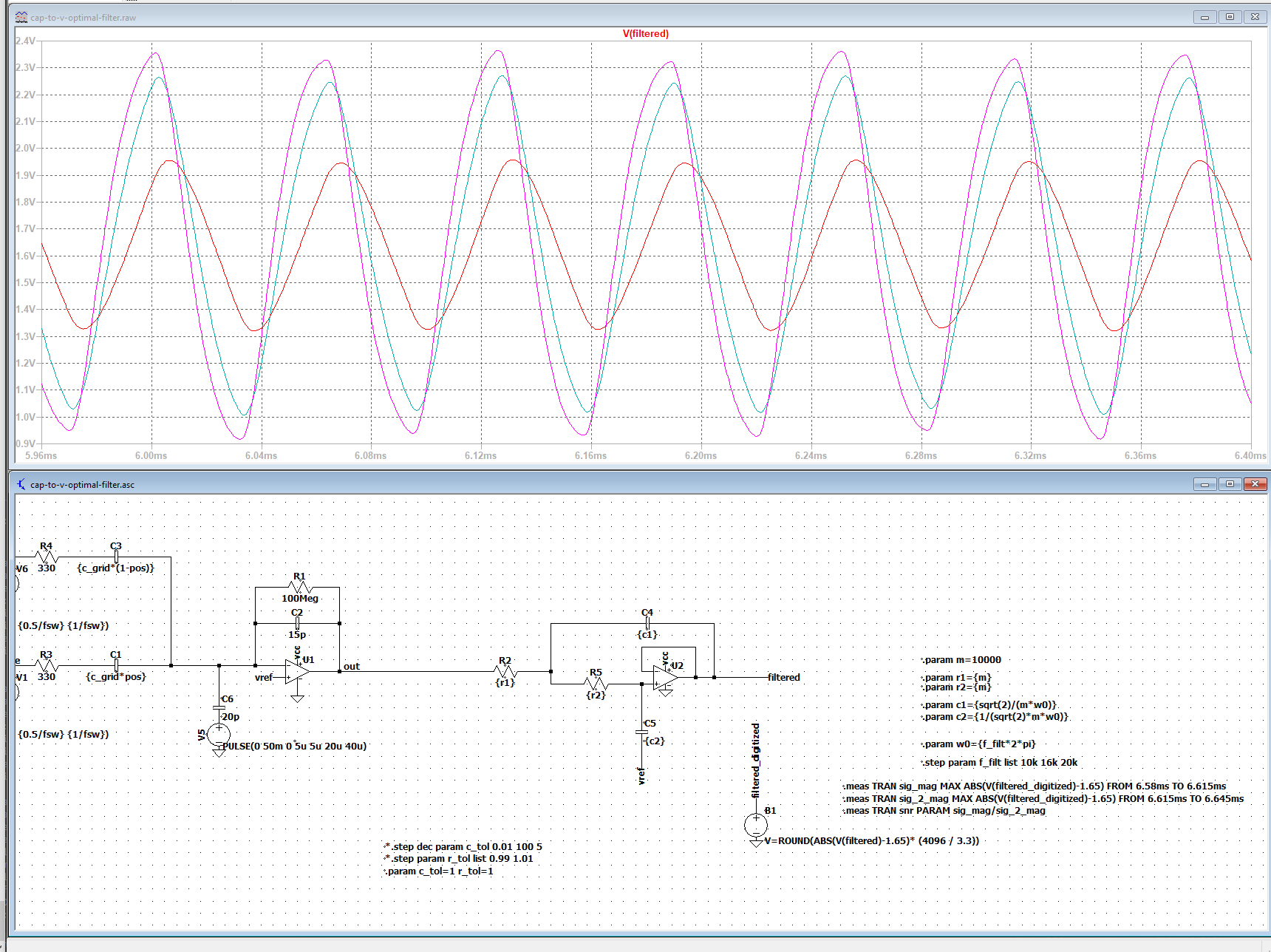
I built the integrator, then added a 16 kHz, 2-pole Butterworth (Sallen-Key) anti-alias filter around the STM32's internal opamp. The ADC is timer-triggered and uses DMA, so the sample timing stays fixed.
![]()
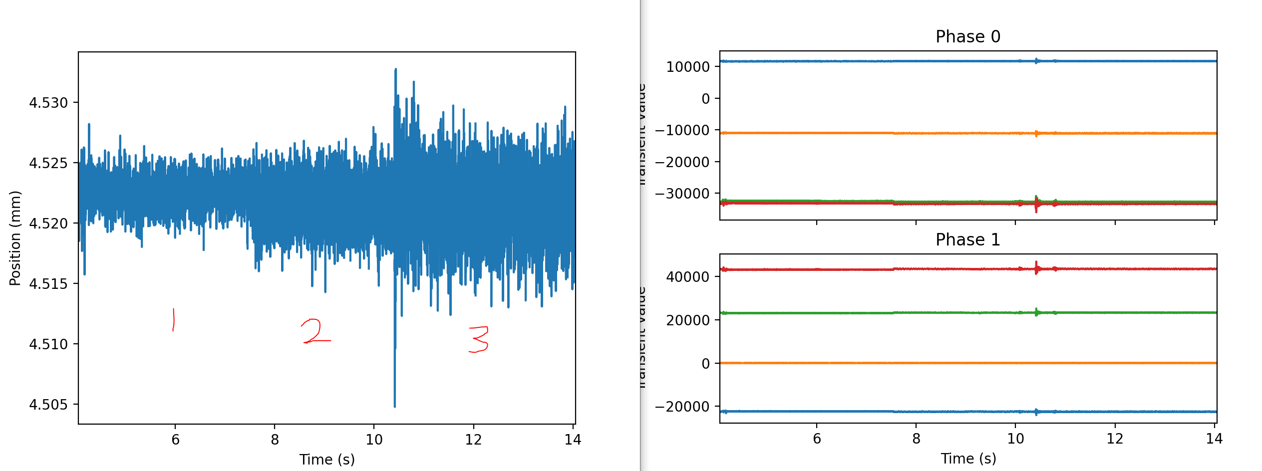
Here's a plot of position error with the printer in various states (off, on with motors off, on with motors on). The error after the integrator and filter is reduced to roughly 20µm pk-pk.
![]()
-
Aug 26, 2026: Chasing Printer Noise
10/22/2026 at 04:11 • 0 commentsI mounted the sensor on my 3D printer's Z axis and swept it up and down in 0.01 mm steps. This was on an older revision of hardware with a more challenging mechanical design, so the whole setup was very wobbly. The results showed where the error came from:
- ~250 µm error from the 8mm pitch printer leadscrew
- ~150 µm electrical noise caused mostly by the printer's power supply and motor drives.
- ~75 µm error periodic with each emitter
- ~50 µm hysteresis error in the 3D printed test mount
After seeing this, I set out to design a better mechanical fixture, since that was the largest source of error.
But focusing on the sensor performance, the noise was the first issue I wanted to tackle.
The printer's power supply switches at about 23 kHz, far above my 1 kHz output rate, so it folded down into the signal where no digital filter could reach it. There are also large motor-noise components around 40kHz and 2~3 harmonics.
I could just shield the sensor here, but I was already getting noise from my UART output too. The printer created a good predictable noise that I could turn on/off and test improvements against to develop a more robust treatment of noise in the analog frontend.
I started with some software improvements to make sure my sample frontend was working as expected.
- I cut the delay between switching the emitters and sampling the RX antenna. A shorter delay pushes the noise further into high noise frequencies.
- I moved the timing-critical code into assembly so the compiler can't change it and added data sync barriers to eliminate delay jitter from memory-write caching.
- Noise fell from ~150 µm to ~100 µm peak-to-peak. The improvement was good, and the improvements are important, but I really want my noise floor below my accuracy floor.
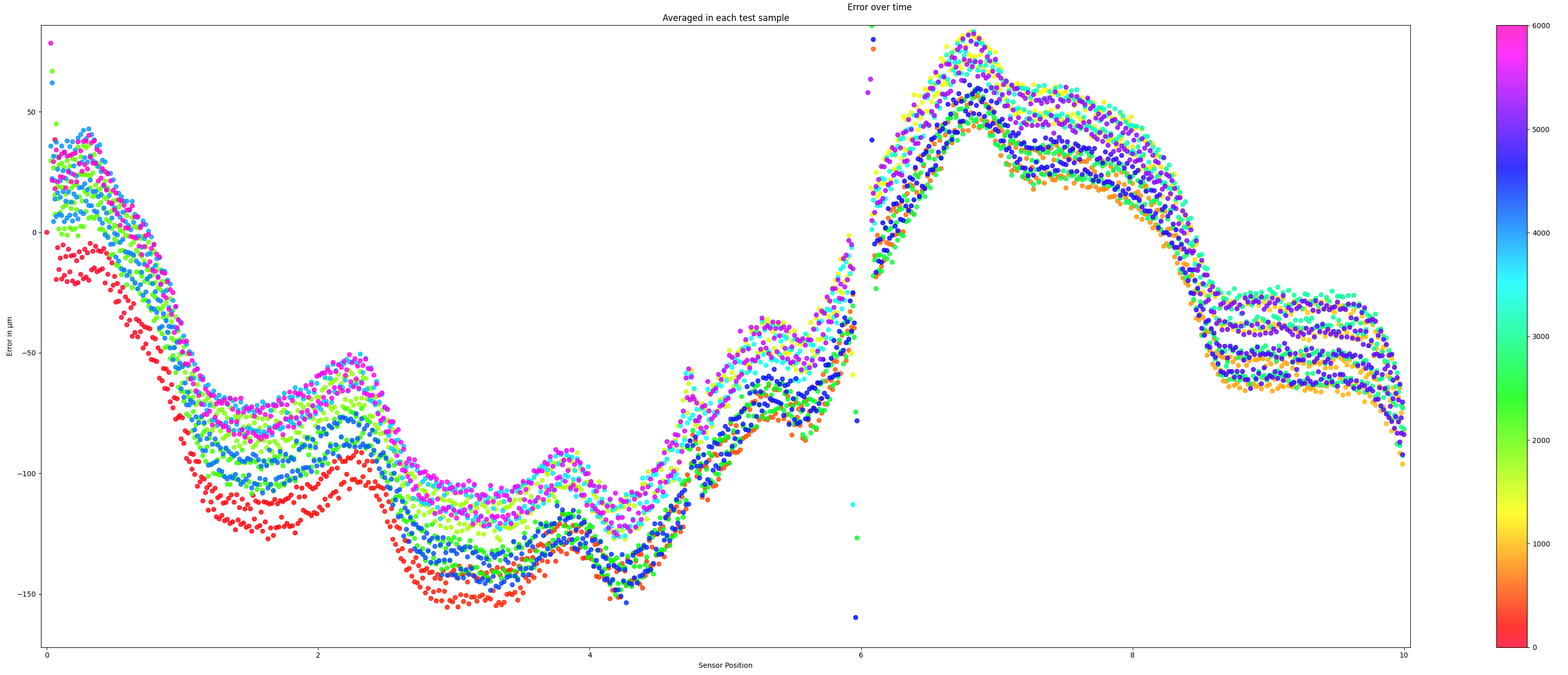
Here is a plot of the error of the first test when moving the sensor up and down across 10mm 3 times (6 sweeps). The color is the sample number. For example, all the red and orange points, from left to right, are the first sweep moving up. If there was no hysteresis in the build, all the lines back and forth would be overlain. Note that the noise isn't shown here, only averaged accuracy over 2 seconds.
![]()
Open-Source 40um/1.6thou Capacitive Encoder
An open-source capacitive linear encoder using same operating principle as the digital calipers you can get on amazon.