Antti Lukats
-
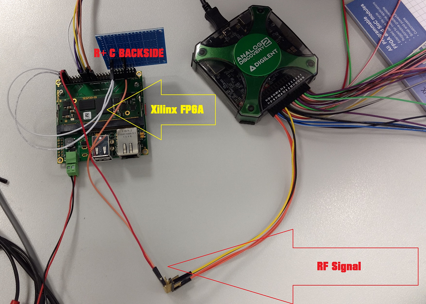
First proto setup
04/06/2017 at 17:51 • 2 commentsThis is the first lab setup I made. The R+C are on the backside of the blue proto PCB
![]()
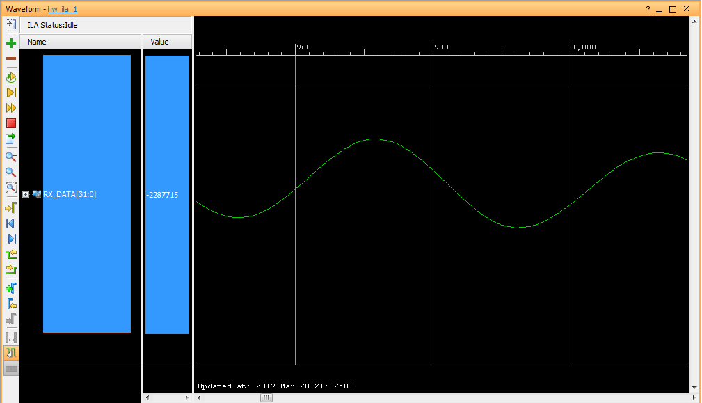
Yes the same setup was tested with 500Mhz signal as well..
-
And 500MHz tested as well..
03/30/2017 at 14:53 • 2 commentsWhen I posted the challenge, assuming that the circuit works at frequencies 500 + MHz.
But I had not tested it.
![]()
Now I have, this is 500MHz signal received with the same 4R+4C lab setup I used for first tests at 3.5MHz.
SNR is not good, actually its really really bad, but hey this is hand soldered prototyp on prototyping board, and the 500MHz frequency is pretty hard to some dirty circuit soldered on generic protoboard. Also the R and C values are not at all optimal, I did not change them, as I only wanted to see proof of concept that it works.
So basically the same circuit can receiver from below 1MHz to 500+ MHz.
-
Almost solved, stage #1
03/29/2017 at 06:39 • 0 commentsThe Challenge went online at Xilinx.com also today
There is already a solution close enough to get accepted for the UltraFast category. Close enough but not the same as my solution. But no more hints at this point.
So lets the Challenge to continue, so other have some chance too.
-
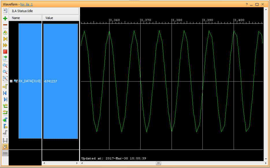
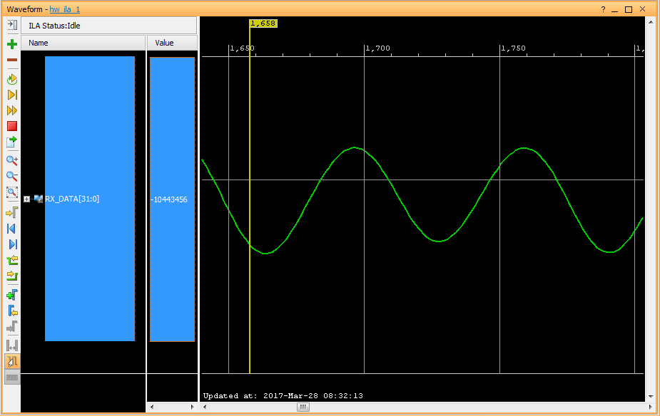
3.51MHz and 200 microvolt, we have signal!
03/28/2017 at 14:55 • 0 commentsAfter I figured out that this may actually work I could not hold back any more. Some of the resistors I found where 0402 size but they are still easy to solder on plain normal perforated prototype board. A few hours later I did see the radio signal received and converted to digital inside the FPGA.
![]()
This is how 200 mV signal at 3.510MHz feed into FPGA using 4R4C Radio Receiver Circuit looks like.
![]()
Ok and here we have signal at 200 microvolt. I had to build an attenuator to get signal level down.
4R4C - FPGA Radio Challenge
We have 4 Resistors, 4 Capacitors and 1 FPGA to make RADIO Receiver.