Yann Guidon / YGDES
-
How fast vacuum tube logic can be?
05/25/2020 at 07:45 • 0 commentsI started experiments with logic element circuits to understand the performance of one logic element - a vacuum tube.
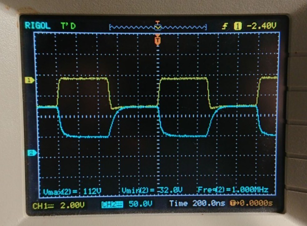
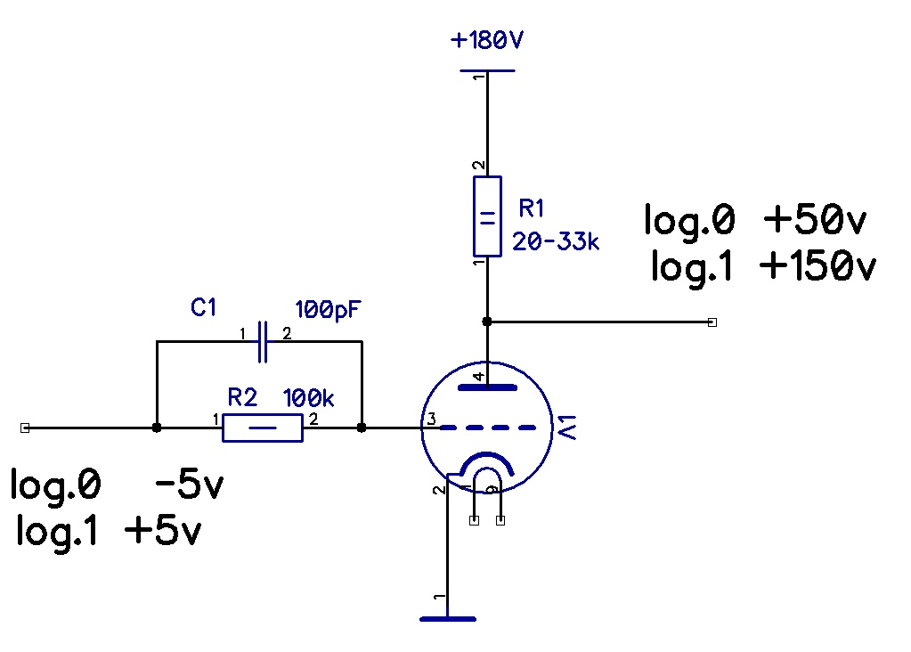
I found, that triode in a simple circuit from IBM 604 can handle up to 1 MHz square signal with appropriate front. But 6N23P was used - it's a high frequency triode. This is very slow for my purposes - If i wan reach 1MHz clock - Out edges must fit into 50ns.
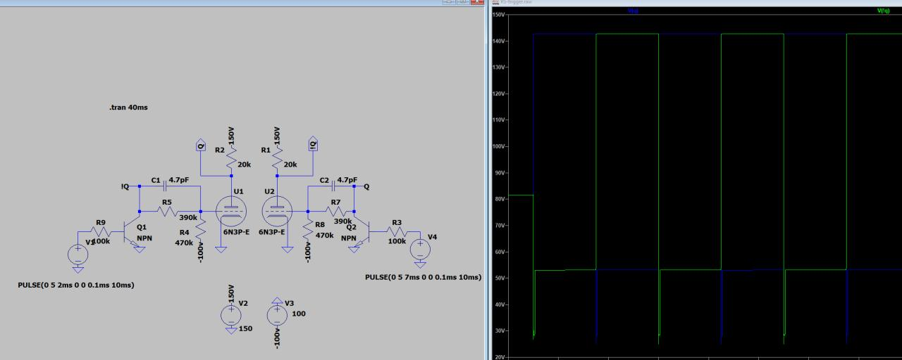
Orange signal - control grid, 30ns edges, Blue signal - anode. Rising edge 200ns.
First schema to test. Anode resistor can vary in 5-33k, but doesn't influence the fronts.
-
Vacuum tube RS Trigger
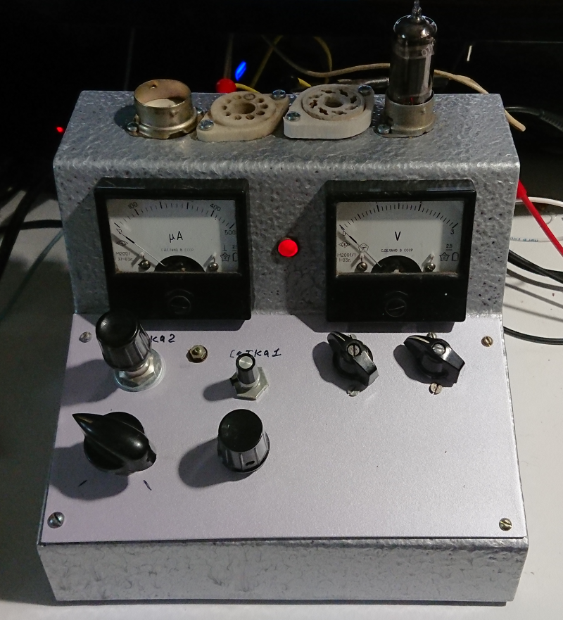
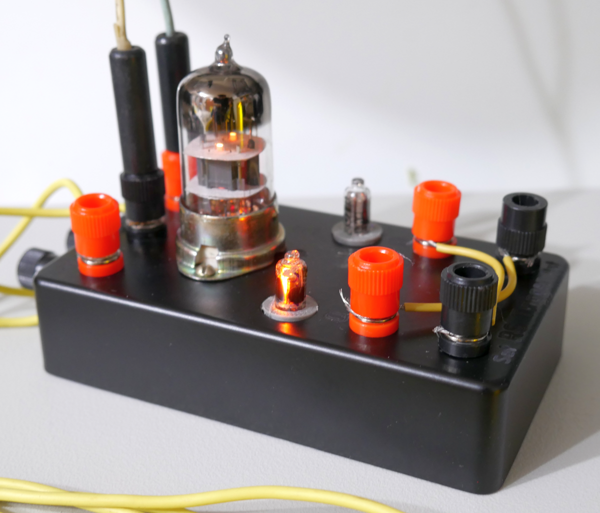
01/13/2020 at 18:00 • 4 commentsI started experiments with vacuum tube-based logic and decided to implement RS trigger on Double triode 6N3P
Here you can see, how it works in real:
![]()
So, It works. I used circuit from the IBM 604 manual and tried to simulate it as a first step:
LT Spice allows me to check all nodes voltages and parts currents. There is no transistors in the real device - I used it just to driver the simulation model.
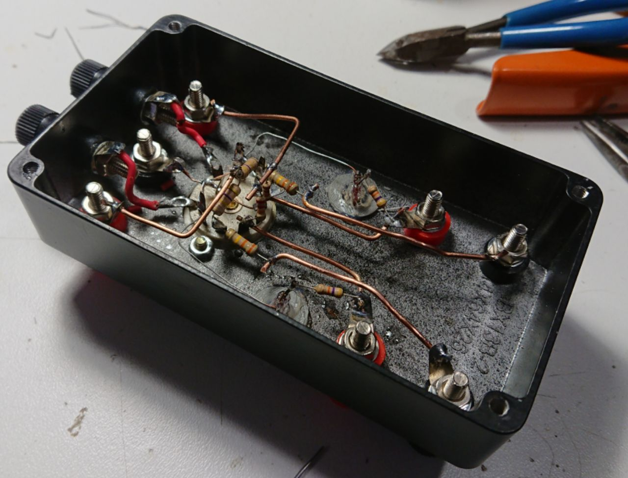
This is my first 3D-assembled device. It could be better, but...
There is +200V anode supply and -100V grid bias.
Logical levels for this schema - +150V for log.1 and +50V for log.0
-
ENIAC and the FlipFlops
04/17/2017 at 08:54 • 0 commentsHahaha it sounds like a Rockabilly rock band :-D
More seriously I'm gathering my thoughts after (re)finding the sources and (re)interpreting the data.
I looked at the paper by Burks about the design of the ENIAC and admit it's a really impressive project. Somewhere it says that the flip-flops have two versions : one version with one triode and one with two triodes. The 2T seems easy to grasp but how is it possible to use only one triode ?
It became clear when I looked at that project (thanks to Tom Anderson) that tries to recreate a single ENIAC flip-flop. A few things became apparent :
- The distinction between FlipFlop and RS latch is not clear and it seems they use mostly transparent latches, not edge-triggered registers. We engineers of today are pampered and spoiled !
- The text should have mention "double triodes" or "envelopes" because not only is it not possible to latch with just one triode but the schematic shows that the two circuits are in fact with 2 and 4 triodes.
- Diodes would have simplified and eased the design of the Flip-Flops (and the programming panels, which use resistors). However, reliable and efficient diodes became available when Silicon took over, and the IBM 604 manual (1958 era) still mentions that diodes are used only when really necessary, as they seemed to be much more expensive znd fragile than tubes. You just can't make a computer using radio receiver's cat whiskers. This confirms what I learned with the #YGREC-РЭС15-bis : without good diodes, computing machines are possible but they can't take off...
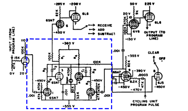
Further looking at the ENIAC schematic, I am shocked:
![]()
Seriously guys, how many power rails do you even need ?
-555V, -470V, -450V, -390V, -360V, -355V, -285V, -200V, 0V, 20V, 50V, 225V, that's 12 rails just for this circuit !
I was complaining that I had to provide 2 supply voltages (filament and anode) but this is simply insane.
OTOH this explains how they do level shifting and AND gates: they shift the tubes, not the signals. This is getting insane...
The IBM604 is more rationalised and engineered (yet still energy wasteful), with only -100V/0V/150V...
Speaking of big bad supplies, I remember I hacked one together 20 years ago out of an old guitar amp transformer, as I wanted to use it to create my own LM3886-based bass amp. This is a symmetrical high-current, pretty high voltage supply that could work with this project... Now I have to find it in my archives :-D
-
Thank you
04/16/2017 at 01:09 • 2 commentsThank you @Benchoff for the feature today on the main Hackaday page :-)
May I suggest you something ? Don't hesitate to contact me before you publish something about my projects :-)
There are several benefits:
- I can provide you with high resolution pictures, not pictures I cropped for the had.io page layout.
- I can correct little mistakes (for example I found 2 pairs of tubes :-) )
- exotic technology is great and I'm all for it but this project barely started, while I have much ambitious and advanced projects : the #YGREC-РЭС15-bis goes way beyond the odd useless techno curiosity, I think it's a much more subject-worthy project with a lot of implications (indirectly to #F-CPU). Come one, I haven't even prepared a first power-on of the tubes :-D
You know how to join me and I'm 200% invested to make HaD gre^Wawesome :-)
-
tube logic
04/11/2017 at 02:07 • 4 commentsI'm still a bit puzzled by how to do logic circuits with tubes.
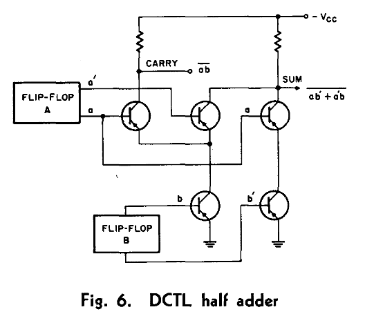
Looking at an old report about transistors, I see the following diagram using DCTL (Directly Coupled Transistor Logic, such as used in the CDC6600):
![]()
Doing a XOR is pretty easy, thanks to the ability of transistors to work in parallel (OR) and series (AND).
At first sight, triodes can only do OR because the voltage differential between anode and cathode is so high !
The differential is usually overcome with a coupling, DC-blocking capacitor, at least in audio circuits, which makes the tubes work only in pulse/transient mode, which is not desired.
The pentodes have differentials of 0V-45V-60V so maybe a 15V Zener could work to make AND gates, but am I daydreaming ?
I should look at the schematics of the ENIAC, when I find the link again.
Thanks to the many comments on https://hackaday.com/2017/04/15/hackaday-prize-entry-hot-logic I found and recovered several resources about tube logic.
Daaaammmnnn....
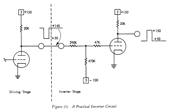
For example I found the following circuit in the IBM 604 manual (1958 era):
![]() What ?
What ?Resistors ?
-100V ??
Maybe I'm too modern and I know "it works" but I think it's just ridiculous...
Other converging resources about the ENIAC, covered by @Al Williams:
The data matrices use resistos, not diodes...
-
valve circuits
04/09/2017 at 22:22 • 7 commentsAs I try to unlock the last know issue with #Yet Another (Discrete) Clock (namely : amplification without affecting the oscillator or wasting energy), I stumble upon very nice pages about the circuits of yesteryears in the audio range. In particular I find the discussion in 8 - Cathode Follower very refreshing and useful (the kind I'm looking for in this type of WTF project with no direct usefulness). I learn about the existence of internal plate resistance (rP), the degeneration of tetrodes and pentodes when used as cathode followers...
I just have to quote a useful paragraph, about something else I didn't find elsewhere or that could discourage me :
One always has to be careful with valve circuits though, as it's easy to exceed the maximum allowable cathode to heater voltage because the heaters are nearly always ground referenced. If the voltage is exceeded the valve may be damaged, but even if it survives it may not function properly.
[...] Unlike JFETs, there is a definite limit to the upper value of the grid resistor, determined largely by the materials used and the geometry of the valve's internal structure. If the resistor value is too high, the valve will attempt to bias itself as the grid collects stray electrons. This is called 'grid leak' or 'contact' biasing, and generally uses a resistor of around 2.2MΩ to 10MΩ or thereabouts. The tiny current flow (typically less than 1µA) causes a voltage to be developed across the grid resistor (negative at the grid) which biases the valve. In general, grid leak bias is rather unpredictable and is usually a bad idea, and it should be avoided.
The page describes a simple current amplifying circuit (impendance buffer) with many details that are rarely mentioned otherwise, and precious because, since I won't build an amplifier, I won't follow well-established circuits and I'll be on my own, trying to decypher ENIAC's diagrams...
So I learn that 1M Ohms is a reasonable grid resistor. It will be fine because I'll remain in the digital domain but even there, the "contact biasing" will bite when several inputs will be connected together. Fan-in seems to be an issue since the grid resistor must be divided by the number of grids, or else "things will turn bad". But lower impedance means higher driving current, larger capacitances, more RC delays and more amplification...
As I consider a 8-bits circuit, this should not become insurmountable but will be another area to keep in mind during the design.
Then there is this link to a pretty practical page about the tubes: http://sound.whsites.net/valves/index.html
The warning about high voltages is why I chose low-voltage pentodes ;-) but this is a chilling reminder concerning the 200V needed (according to the available informations) by the 6N21B.
Thanks to Elliott Sound Products for sharing their experience :-) I'll remember this quote :
'guitar amp' and 'careful engineering' generally do not belong in the same sentence.
-
And the PSU
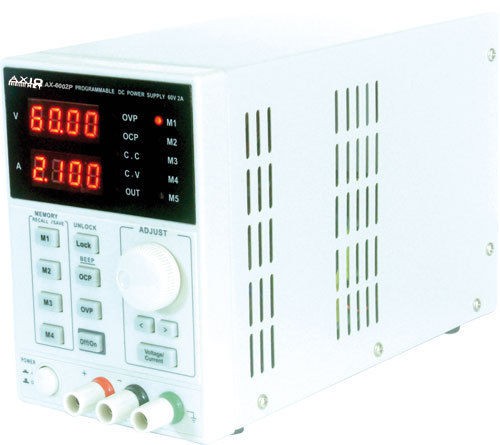
04/09/2017 at 03:41 • 7 commentsSo now I can generate 61V@2.1A though I can't seem to control it via USB. Yet.
But it's already a game-changer for my lab :-D
Update 20170417 : the stack entry has been deleted :-(
I had noted a few things, I'll try to remember them and write them down here.
Update 2: ah no, it's there : https://hackaday.io/page/3068-advicesinfos-about-usb-connected
But it's good to have a second copy ;-)
![]()
The model is AXIOMET AX6002, a rebranding, as I later found, of KORAD KA6002, but discovery was not obvious.
I bought this model on eBay because
- it reaches 60V (a match for the pentodes)
- it's digital, easy to set precisely
- it's not much more expensive than other models
- it is interfaced with serial and USB ports !
4th sealed the deal.
When plugged in the computer, the serial port is immediately found (OK, I first have a dud cableso it wasn't as smooth.
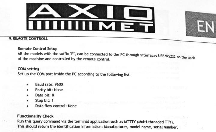
The documentation is quite terse:
![]()
I have the protocol (9600 8N1) so I can configure the port:
TTY=/dev/ttyACM3
stty 9600 cs8 raw -echo -echoe -echonl -echoprt -echoctl -echoke -parenb -F $TTY
but the last paragraph misses a critical information : what query to enter ?
I went to the Axiomet website too look for information and found the newer model. The documentation mentions:
Interface:USB interface, SCPI commands provided
Oh, let's look that up. SCPI is a standard I hadn't spotted yet ! So I embark in the analysis of the specifications.
I find that the discovery string is "*IDN?" so I try to read it:
echo -n "*IDN?" > $TTY
It took a while to get anything, and to understand that contrary to the specification, the commands should not be terminated by CR/LF, so I added the "-n" option to echo.# in another term: $ od -An -v -w1 -t x1 $TTY 4b 4f 52 41 44 4b 41 36 30 30 32 50 56 32 2e 30 00
In ASCII :
$ cat $TTY
KORADKA6002PV2.0
After a few hours, I got the device's string, that returned no hit on google...
So I wrote a .stack page (unfortunately deleted now) and asked for help. I got it (from @Andrew Bolin) with a link that started bring sense to the whole situation because I tried most of the standard commands without finding anything else that would work, with or without the trailing CR/LF.
On the EEVBlog,I find that the device is not KORADKA but the brand KORAD, model KA6002P !
I learn about the bug (reproduced here) with the trailing letter, then discover the whole command set.
(the most important are copy-pasted here)
Request Example output Remarks *IDN? KORADKA3005PV2.0
VELLEMANPS3005DV2.0
VELLEMANLABPS3005DV2.0Request identification from device. VSET1? 12.34 Request the voltage as set by the user. VSET1:12.34 (none) Set the maximum output voltage. VOUT1? 12.34 Request the actual voltage output. ISET1? 0.125 Request the current as set by the user. See notes below for a firmware bug related to this command. ISET1:0.125 (none) Set the maximum output current. IOUT1? 0.125 Request the actual output current. OUT1 (none) Enable the power output. OUT0 (none) Disable the power output. OVP1 (none) Enable the "Over Voltage Protection", the PS will switch off the output when the voltage rises above the actual level. OVP0 (none) Disable the "Over Voltage Protection". OCP1 (none) Enable the "Over Current Protection", the PS will switch off the output when the current rises above the actual level. OCP0 (none) Disable the "Over Current Protection". I see several project that interface to the same line of devices, in Python and Ruby for example, but the thing is now very simple to command, even with bash. Here is a little "vocabulary" :
echo -n "*IDN?" > $TTY
echo -n "ISET1?" > $TTY
echo -n "OCP0" > $TTY
echo -n "OCP1" > $TTY
echo -n "OUT0" > $TTY
echo -n "OUT1" > $TTY
echo -n "OVP0" > $TTY
echo -n "OVP1" > $TTY
echo -n "ISET1:0" >> $TTY
echo -n "VSET1:0" >> $TTY
echo -n "STATUS?" > $TTY
echo -n "VOUT1?" > $TTY
echo -n "VSET1?" > $TTY
# ramp up the voltage from 0 to 60V
for i in $(seq -w 0 60)
do
  echo -n "VSET1:"$i >> $TTY
  sleep .1
done
#ramp up the current from 0 to 999mA
for i in $(seq -w 0 999)
do
  echo -n "ISET1:0."$i >> $TTY
  echo $i
  sleep .1
done
So these are not actual standard-compliant SCPI commands but they are good candidates for transport over #HTTaP
-
1Ж29Б-В (1J29B-V) arrived too
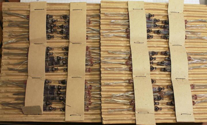
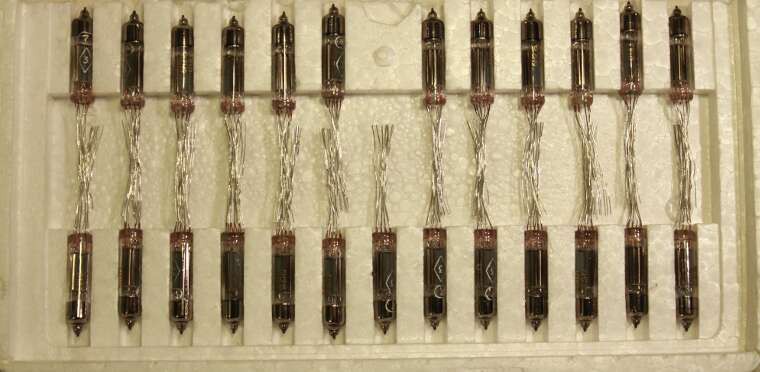
04/05/2017 at 06:48 • 2 commentsreceived these pentodes from Moldavia and they look lovely !
![]()
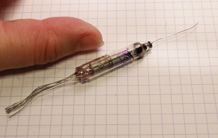
This tube is funny because it has a wire on the top:
![]()
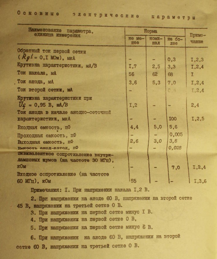
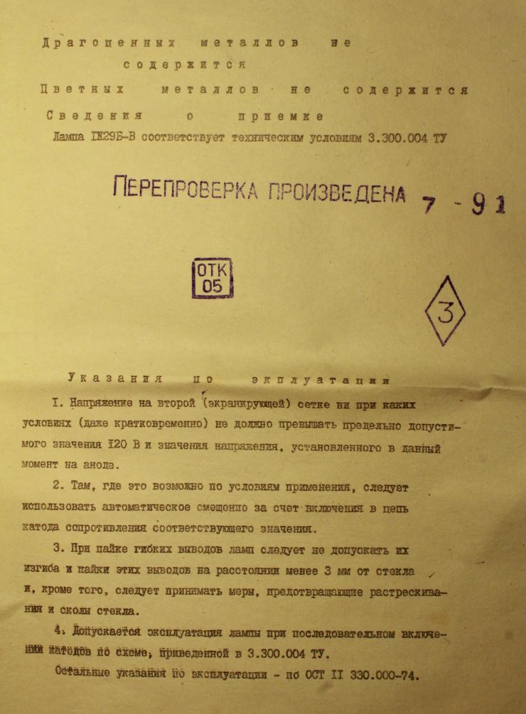
The "etiketka" needs some explanations but the characteristics can be found on many web sites. I put these here "for reference":
![]()
![]()
.
![]()
OK, sorry, I don't understand Russian, I barely decypher a bit of cyrillic :-P (see the project #Clockwork germanium)
According to online resources :
Type : penthode
Application: HF voltage amplification
Cathode type: oxide, direct heating
Envelope: glass, miniature
Mass: 4,5g
Filament voltage: 1,2V/2,4V
Filament current: 56-68mA/31mA
Anode voltage: 60V
Grid1 voltage: 0V
Grid2 voltage: 45V
Steepness: 1,2mA/V
Reverse grid current: 0,3µA
Microphnic noise: 130mV
Socket type: flexible..
I'm pretty curious about the anode wire that extends from the other end... why there ? and won't that complicate the physical design ? Considering that the anode will receive the high voltage, it will certainly be tricky and not "kids friendly" like the relay computer...
The filament current is much lower than the 6N21B: I think it can run at (min.) 50mA@1.2V (60-80mW) instead of the 2W (at least) required by the dual-triode... so at least, this one was a good bet.
-
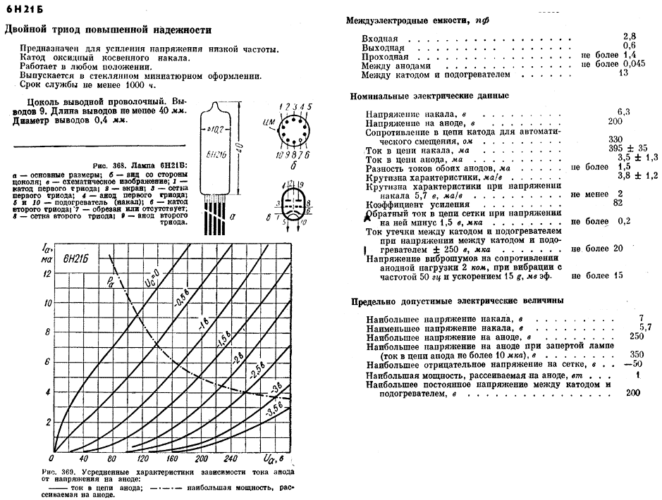
The 6Н21Б (6N21B) are cute !
04/05/2017 at 06:00 • 0 commentsI received the 6Н21Б from Sotchi and I see the difference with the "classic", AF tubes : they are smaller :-)
![]()
I decided not to play with nuvistors and the miniature tubes are right what I had in mind, the object in itself is pretty good looking.
From the seller:
6N21B = 6112 = 6N17B-V ~ 6SL7 Gold Grid Hi-mu Double Triode NOS
High durable low frequency high-mu dual triode
Improved version of 6N17B-V / 6N17B-VR , 1W anode power dissipation ( 6N17B-V / 6N17B-VR only 0.9W )
Very low microphonic noise , 4 times better than 6N17B-V / 6N17B-VR
Different pinout than 6112 / 6N17B-V / 6N17B-VR / 6SL7, see datasheet !
Each tube contains 5.05 mg gold and 0.05 mg silver !This one didn't come with an etiketka/passport, so I have to rely on other resources. They are easy to find online (which helped me decide on the appropriate reference) and here I copy-paste the data from http://tubes-store.com/product_info.php?products_id=732 (I further the long tradition of copy-pasting it from everywhere).
Name: 6N21B
Type: Double triode, hi-durable
Application: LF voltage amplification
Cathode type: oxide, indirect heating
Envelope: glass, miniature
Mass: 4,5g
Filament voltage: 6,3V
Filament current: 0,36-0,43A
Anode voltage: 200V
Anode current: 0,0035A
Anode power: 1W
Steepness: 2,6-4,0mA/V
Reverse grid current: 0,2µA
Microphnic noise: 15mV
Gain: 65-100;
Socket type: flexible;
Lifetime: more 2000 hours.I have chosen these because they have a better amplification coefficient than the (slightly cheaper) 6N17B-V. I'm not doing audio and I don't care about linearity ;-) This also means I can undervolt the filament to increase their lifetime and save a bit of energy. Though who in their right mind would use these for 2000h ?
Oh and 200V on the anode ?
I'm not sure if the below curves (found at various websites) tells us the voltage can be lowered:
![]()
I might have to learn some Russian, one day.
And it seems I'll have to plot my own curves and find the right operating conditions.
It seems that the stories I heard about early "tube computers" that reduced the heater voltage (to increase reliability) may have overlooked something. From Rod:
"The heater voltage is far more critical than some people imagine, and if too low, the result can be cathode poisoning - a condition where the cathode materials are contaminated by trace amounts of gas."
So in the case of this tube, I'll try to run at the lower end of the range, around 0.35A or so. That's 1/3 of an ampere, or 2W, damnit, and heating 50 of these tubes will draw 100W ! It's ironic since I chose the miniature ones to save power... Yet the insides heat in the 700-800°C ballpark.
I found approximate equivalences. According to http://www.effectrode.com/signal-tubes/subminiature-tubes/, http://www.seymourduncan.com/forum/showthread.php?73998-Tubes-6021-vs-6021W,
"The 6N16B can be substituted for U.S.A manufactured 6021 and 6N17B for 6112 subminiature tubes."
"6021's european designation is Ecc70, and also NJ7P, it only has a gain factor of about 30"
So once again the russians just copied the design though they kept using it much longer than other countries...
Knowing the equivalences lets me extend the research of other compatible schematics and circuits...
Hot logic
Ridicule doesn't kill but HV does. I hope to avoid both while using some 1Ж29Б-В and 6Н21Б
 What ?