0%
0%
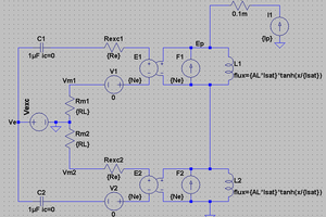
Tusotek DC/DC Boost - Constant Current
How to modify the low-cost "Tusotek 200W DC/DC Boost Converter module" to be a Constant Current controlled converter (boost LED driver)
 benjaminaigner
Become a Hackaday.io member
Already have an account? Log in.
Just one more thing
To make the experience fit your profile, pick a username and tell us what interests you.
Pick an awesome username
hackaday.io/
Your profile's URL: hackaday.io/username. Max 25 alphanumeric characters.
Pick a few interests
Projects that share your interests
People that share your interests


 jbb
jbb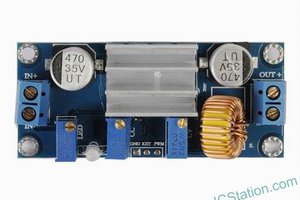
 icstation
 Simon Merrett
 Kevin LO
Can any one please tell me whats the name of those mosfets i also accidently broke them of while removing heatsink!
Thanks in advance