danjovic
-
First working firmware ready!
04/02/2017 at 23:00 • 0 commentsThe first working firmware is already working. There is room for improvement, though.
The whole code is available at github but the main components are here:
1. The keyboard is read with a small delay betwenn the changes in I/O direction and the reading
  // Set P1=0, P0,P2 = inputs with pullup
  pinMode(0, INPUT_PULLUP);   // P0
  pinMode(1, OUTPUT);         // P1
  digitalWrite(1, LOW);
  pinMode(2, INPUT_PULLUP);   // P2
  DigiMouse.delay(1);
  if (digitalRead(0) == 0) button_state |= (1 << 2); // Left
  if (digitalRead(2) == 0) button_state |= (1 << 3); // Right

  // Set P1=1, P0=0, P2 = input with pullup
  pinMode(0, OUTPUT);          // P0
  digitalWrite(1, HIGH);       // P1
  digitalWrite(0, LOW);
  // pinMode(2, INPUT_PULLUP); // P2 no change, still input
  DigiMouse.delay(1);
  if (digitalRead(2) == 0) button_state |= (1 << 0); // Up

  // Set P1=1, P2=0, P0 = input with pullup
  pinMode(0, INPUT_PULLUP);    // P0
  //  digitalWrite(1,HIGH);        // P1  no change from last state
  pinMode(2, OUTPUT);    // P2
  digitalWrite(2, LOW);
  DigiMouse.delay(1);
  if (digitalRead(0) == 0) button_state |= (1 << 1); // Down
2. The readings are analyzed to detect changes from the last scan.
  if (button_state != last_scan) {
    last_scan = button_state;
     ....
     ....

  }
3. The (former) useless combinations (UP+DOWN, LEFT+RIGHT) are disregarded and the sensitivity index is advanced or regressed when keys LEFT and RIGHT are held together and the keys UP or DOWN are pressed
    // Eliminate useless sequences: L+R
    if ( (button_state & 0x0c) ==0x0c ) {
       // Do L+R Stuff
       if ( (button_state & 1) && (fib_index < (MAX_FIB_INDEX-1)) ) fib_index++ ;  // Up
       if ( (button_state & 2) && (fib_index > 0                ) ) fib_index--;  // Down

      } else {
           if (button_state & 4) DigiMouse.moveX(-fib_step[fib_index]);  // Left
           if (button_state & 8) DigiMouse.moveX( fib_step[fib_index]);  // Right
     }

    // Eliminate useless sequences: U+D
    if ( (button_state & 0x03) == 0x03 ) {
       // Do U+D Stuff
       fib_index = 0;  // U+R reset fib index
      } else {
        if (button_state & 1) DigiMouse.moveY(-fib_step[fib_index]);  // Up
        if (button_state & 2) DigiMouse.moveY( fib_step[fib_index]);  // Down
     }
The sensitivity is increased/decreased according to a slice of a fibonacci sequence.
const uint8_t fib_step[MAX_FIB_INDEX]={ 1, 2, 3, 5, 8, 13 };4. Finally a small delay is added as a primitive debouncing method
DigiMouse.delay(5);
So far that's all folks!!
-
The 3rd out of 2 options!
04/02/2017 at 21:54 • 0 commentsThe third of two options to connect the potentiometer is not use the potentiometer at all, instead use useless key combinations for instance
hold LEFT+RIGHT pressed at the same time then use UP and DOWN keys to select sensitivity. To make things more interesting use a fibonacci sequence for the sensitivity, I mean the steps will be
1, 2, 3, 5, 8
And the combination UP+DOWN to reset to 1, just in case one get lost in the size of the step.
Now let't get back to the bench and code like there's no tomorrow until the job is done!
-
Adding a slider... Adding?!
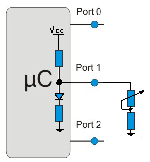
04/02/2017 at 21:42 • 0 commentsThe first thing that came to my mind to add a slider was to use a potentiometer in series with a 1K resistor.
![]()
Then I remembered that the ground is not available at the I/O header.....
![]()
This is bad... very bad.... It leaves me with only two options.
- Add the GND using a wire
- Use the RESET pin
- Hey, there is a third option here! dont't ya think this project has already many buttons? use them smartly!!!
-
Charlieplexing with a biased input
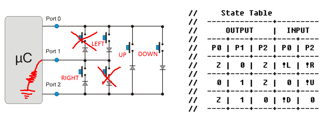
04/02/2017 at 21:10 • 0 commentsWith 3 pins available it is possible to get 6 switches by charlieplexing. It is prone to ghosting, though.
Since one of the pins I have available (P2) is biased to ground I was able to get only 4 without ghosting.
On the table below Z represents input with a pullup.
![]()
Next challenge is to add a pot slider to this cauldron ans stir while spelling some witchery....
-
Design considerations
04/02/2017 at 20:50 • 0 commentsThe Digispark is a cheap and easy board to build USB devices, but the original circuit suffers from some unlucky design choices:
- The fist one is the LED connected from the pin P1 to the ground (through a resistor, of couse) which bias this pin to ground.
- The second is that the header with I/O pins does not contain a GND pin (neither a VCC line)
- The third one is present on the chinese clones. The pin 5 not programmed as an I/O line but as a RESET pin.
The three issues above makes the life harder when you aim for a minimalist design like in the present project, but let's pour the cards on the table:
As for the resources:
- We have three I/O pins available
And the limitations
- One of the I/O pins is biased to the ground
- No GND at I/O header
Now the demands for this project
- Four keys that might be used in combination (diagonals)
- A potentiometer for selecting sensitivity
- Minimum extra parts involved
- Shall be attached only to the I/O header
Easy Peasy!!
Mouse Aid
With this companion your mouse will be able to perform fine and precise movement in drawing applications