 ptrav
ptrav-
1Step 1
Decide if you need a stationary chorded keyboard. This piece is designed for those who work at the comfortable desk! If you look for a "wearable" chorder, there are other devices around. This design presumes full use of both hands, but may be modified for one-handed operation, similar to the BAT Personal or CyKey. You may even convert it into a cool gaming keyboard by adding SZXC under the left hand.
-
2Step 2
Assemble materials. If possible, try the mechanical switches to suit your hands. I used the Cherry MX Clear for all buttons. Perhaps, MX Blue would be better for Alt, Control, and Shift. Anyway, for the top boards you need "Tactile", and for the bottom "Clicky" or "Linear".
You will need suitable for electronics soldering iron, a Dremel machine and/or small electric drill, hacksaw with fine teeth, a coping saw, pliers, screw-driver, metal ruler and a scratcher, eye protection. CNC machine is optional.
For programming Arduino, the latest IDE from https://www.arduino.cc/en/Main/Software
-
3Step 3
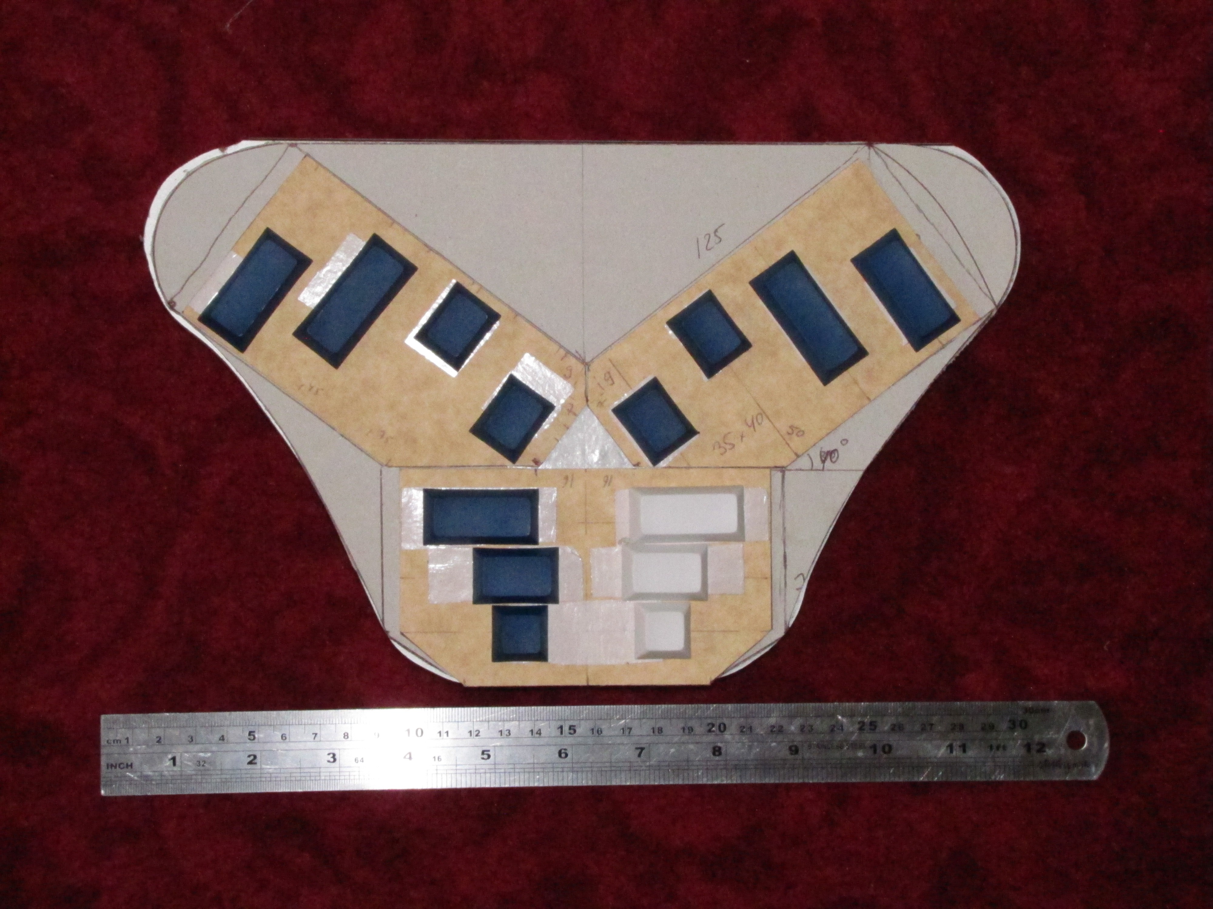
Decide on the finger spacing and button sizes. The best way is to put real keycaps over a piece of carton, but if the keycaps are not available, cut "buttons" from thick packing plastic. The standard button size is 18x18 mm.
After finalizing the layout, cut the PCBs to size (round the size up to the PCB holes) I ended up with the finger spacing of 30 mm (center to center) and the board angle of 36 degrees (do not trust the photo!)
![]()
After cutting, measure the PCBs carefully. The hole spacing may is most likely not 2.5 mm, but 1/10 inch (2.54 mm). Over the PCB size, the length accumulates into an extra length.
![]()
-
4Step 4
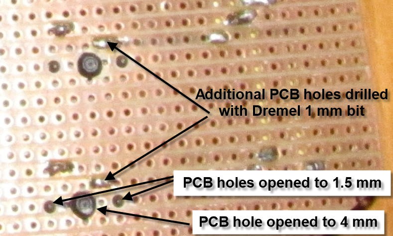
Finalize the button positions and expand the holes. In the middle of the button the hole is 4 mm, then two holes 5 mm away from it must be expanded to 1.5 mm. Finally, drill an additional hole for the pin (better to use high-speed Dremel with 1 mm PCB bit)
Install the key into the holes and check the mechanical operation. If the button is too lose, add a drop of hot glue between the button body and the PCB surface.
Solder the pins to the PCB.
![]()
-
5Step 5
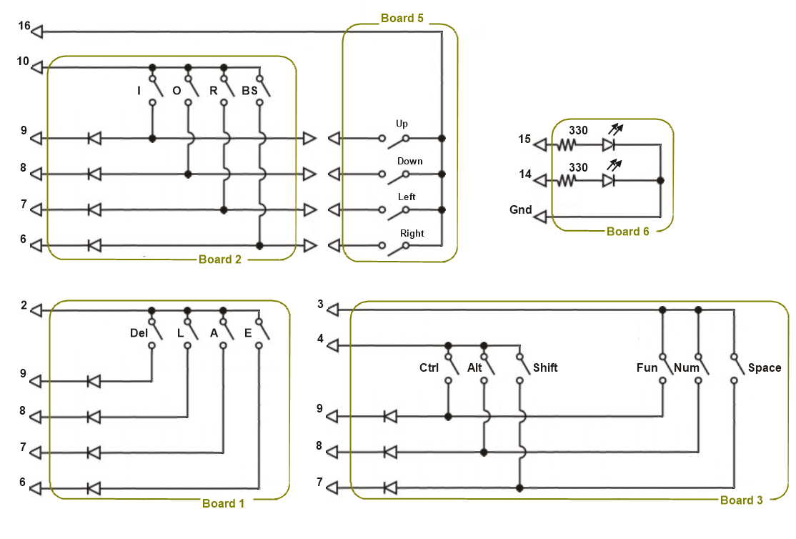
Solder the PCB connectors, diodes and other components. The electronics is elementary, so it makes no sense to have the exact wiring. Besides, the physical shape of your boards may be different from mine.
The wiring diagram as below. My dirt-cheap Arduino-Micro came with damaged pin 5, so I had to move pin assignments a little.
![]()
Board 4 is not shown. It is the Arduino itself. On the diagram the pin numbers correspond to the Arduino pin-out.
The soldered boards look like this:
![]()
-
6Step 6
Connect boards together. Compile and upload Arduino sketch.
Test all buttons.
Two-handed chording keyboard
Filling the vacuum in high quality chording keyboards market.


Discussions
Become a Hackaday.io Member
Create an account to leave a comment. Already have an account? Log In.