Edit: Forked to #Precision current generator
I am soon getting SOT363-DIL adapters so I might soon evaluate the BFS480.
Meanwhile, I must also evaluate the various peripheral circuits, such as current sources and current mirrors. And if I have a digitally controlled PSU, it's not working in a suitable range : I want a better precision, from about some µA to maybe 20mA. A good PSU has a resolution of several mA...
ECL circuits use a bias current of about 4mA but I want to to vary it. And a using a fixed resistor on a 9V battery will not provide enough stability if the output voltage varies...
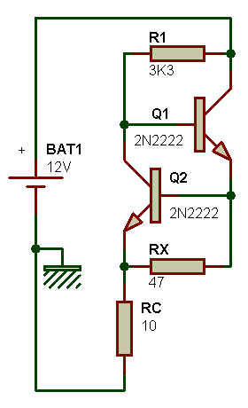
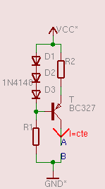
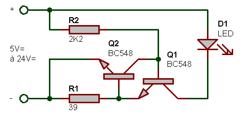
There are many example circuits for current generators, or current limiters, on the 'net. Here is a little sample of what I've found (and links to the pages) :


My design priorities are simplicity, use of basic parts (I don't want to use an IC or Opamp) and "some stability". It will be a high-side circuit (to fit with most NPN current mirrors) so it must use a PNP transistor (as in the last picture).
At first the bias-diode-based circuit (as shown just above, or in the 2nd box of the first image) looks interesting: 2 standard diodes set the base voltage, and more if a range switch is added. Very fine tuning can be added with a series adjustable resistor to change the current. However the bias might not be very stable, with a mismatch of thermal coefficients, and because there would be 2 or more PN junctions on one side, but only one on the transistor side.
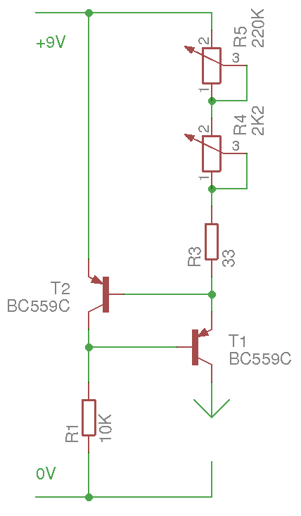
A 2-transistors circuit is chosen, as shown on the pictures. If both transistors are from the same lot (and stuck together), the thermal behaviour should be almost identical and the circuit is a bit more stable (I hope, because there is only one junction). I won't use high currents so heat won't be a significant issue. I can still add a finetuning adjustable resistor, in addition to the main current setting resistor. Its value is approximatively set as follow :
I=U/R=Vbe/Rs= 0.7/R
I have found a nice potentiometer, 220K log, so the minimum current is about 0.7/220000=3µA.
Max current is R=U/I=0.7/0.02=35 Ohms so a fixed 33 ohms resistor is added in series.
Another 2K potentiometer in series (R2) adds more tuning flexibility though (unlike with the diodes voltage reference) I doubt it's actually useful (I'll have to test).
I also want to add a current probe (ammeter) in series...

A single alkaline 9V battery should be enough, but an external PSU can also be used. The voltage difference for the circuit can reach about 8V (9V minus the Vbe and some Vce_sat) but can be increased with a higher supply voltage. The ammeter's drop should also be considered... It varies from device to device so I can't be sure yet.
But for 5V-powered ECL, it should be good enough :-)
OK, the first prototype doesn't work as well as expected but I built it in a hurry... at least I have a fancy box with nice knobs :-)
2nd prototype accepts to work. The 220K log pot is great for the range under 1mA, down to 4,7µA.
The range above 2mA is tricky though, the low-value potentiometer might not be adapted. Maybe a log type would work better. And I still don't know why it was so difficult to make it run correctly, why I measured odd voltages, but I was initially in a hurry so I might have overlooked something.
I want to generate not-too-unreliable currents, up to maybe 10mA. The ammeter measures 17mA when it short-circuits the output. The potentiometer can't set the current reliably above 3mA...
20180711:
I replaced the pot with a 4K7 log model and it works better, though I should really replace it with a 2K2 log model. I can get a good usable range but the higher current values are still tricky, above the 8mA mark. I'll buy one tomorrow.
Meanwhile the case is progressing :-) it looks pretty cool, pictures will come soon...
Now I would love to have an integrated ammeter but I can't find a suitable model. I have one that would be great but that I don't want to damage. The autorange feature is quite handy so I don't have to switch a button everytime the value crosses a threshold. But this model was a freebie from maybe 15 years ago so it's impossible to find another unit...
Well, OK, it was a websearch away : the JT-033A :

and it seems mine has a broken (soldered) probe, so it's not such a bad idea to transform it into a panel instrument, after all... I'll just need a larger box :-D
 Yann Guidon / YGDES
Discussions
Become a Hackaday.io Member
Create an account to leave a comment. Already have an account? Log In.
I've been playing with different bias currents in simulation lately. I'd hoped that I'd be able to get reasonable results with < 1mA, but that doesn't look like it'll actually happen very easily. At about 1mA I'm able to get a buffer to produce a plausible looking output at a toggle rate of 750MHz, but not beyond that. And obviously the faster you want to go, the higher the slew rate you need, the more current you need.
The interesting thing is, though, the stability of the current sink seems to make very little difference to the actual results. Whether my simulation used a resistor or an ideal current source, the output results were practically the same. Conventional wisdom says that a differential amplifier needs a stable current sink, but that seems to only be to prevent distortion. And for a digital signal, we really don't care all that much about distortion.
But what does seem to be important is the stability of the current source to the collectors. It's very easy for the voltage to drop there at exactly the time you need to supply current to overcome the internal capacitance of the transistor, and with a simple current source that obviously causes the current to drop too. But rather than do anything fancy, I found I could fix that by adding a small inductance into the circuit, which really improved my response rate.
Are you sure? yes | no
I'd love to read more about this subject :-)
What is the order of magnitude of the inductor?
Are you sure? yes | no
I got the best response at around 50-60nH, with a threshold just beyond that causing distortion and eventually ringing, but I suspect it heavily depends on the precise frequency response of your transistors and the current loads you're seeing, so probably to be safe dropping to about 30nH would be most sensible.
There's a schematic here: https://easyeda.com/editor#id=|64304ef7d2394a47bb9c27d53624aeaa
Are you sure? yes | no
at 30nH, it's probably possible to wind some wires or use PCB traces :D
Are you sure? yes | no
You can make the 3 diodes single transistor current source circuit with into an adjustable one. Simply add a trimpot across the 3 diodes and connect the transistor to the wipper. Changing the bias voltage would cause a different voltage drop across the R2. i.e. the current
Are you sure? yes | no
yup I know :-)
However I chose the 2-transistors version...
Are you sure? yes | no
reason : changing the bias would also change the "drop", which could interfere with the tested circuit
Are you sure? yes | no
When you starve the circuit by limiting the current, you will be lowering the voltage. Can't change current externally without affect the voltage.
Are you sure? yes | no
yup but I want to keep the margin constrained and the max. drop fixed.
If I use several diodes in series, I reduce the operating margin by as many diode drops.
Are you sure? yes | no