Close
0%
0%

MAD - Modular Audio Devices

A set of Eurorack modules to control synths, make custom MIDI-compatible interfaces and USB audio, powered by Teensy 3.6

Similar projects worth following
NEW, IMPROVED PROJECT PAGE: https://hackaday.io/project/99863-mad-11-modular-audio-devices


Modular Audio Devices (MAD) is a set of Eurorack modules that bridges the gaps between your PC, your MIDI keyboard, your analog synths and your audio interface, by providing means to do all the things! Use the CORE for USB-to-MIDI, MIDI-to-USB, and USB/MIDI-to-CV and control your synths (be them analog or in a DAW), add the IOAPEX to build the MIDI control surface of your dreams, and add the CODEC to record/listen your current masterpiece, all using just ONE USB port!

CORE : hosts the Teensy 3.6, provides a USB port for communication with a PC, MIDI IN and MIDI OUT ports for communication with MIDI devices, a TFT display and encoders for on the fly configuration, 8 CV outs with offset control and 8 gate outs.

IOAPEX : attaches to the back of the CORE, hosts custom logic to control up to 128 digital inputs, 128 digital outputs, and 128 analog inputs using 16-bit multiplexers on sub-modules, in order to create custom control interfaces (with pads, encoders, pots, sliders, LEDs, keyboards etc.)

CODEC : hosts an AK4558 hi-fi audio CODEC with professional level (+4dBu, +24dBu max.) stereo inputs with independent volume control, professional level stereo outputs and headphone output. The module also provides AUX IN and AUX OUT connectors on-board for future upgrades.


Below you can find a list of old prototypes and/or abandoned modules:

IN mini : TRS 1/4" jack or TRS 1/8" jack to Harwin M20 2x3 male pin header, with RFI filter capacitors

IN lite : fully differential stereo line receiver on 2 1/4" TRS jacks to single ended output, with independent volume control, reference level setting (-10dBV or +4dbU) and support for external preamp modules with differential outputs, hosting THAT Corp and TI audio line of opamps

IN hi-z : high impedance instrument preamplifier with single ended input on a 1/4" TS jack, fully differential output and independent gain control, based around TI audio line of opamps

OUT lite : stereo single ended input to impedance balanced (balanced/unbalanced) line output on 2 1/4" TRS jacks, with volume control, secondary headphone output on a third 1/4" TRS jack, switch to select between line out/headphone, with support for auxiliary output amps with single ended input, hosting TI audio line of opamps

PSU D : split supply DC/DC converter with very low noise LDOs, with USB, DC or external power input (max 5.5V), designed for +/-5 V but configurable for up to +/- 15 V, with power output on terminal blocks to provide easy interconnection to all kind of modules, hosting TI line of DC/DC converter and LDOs; USB data lines are offered on a soldering header in order to connect the USB port to the Teensy

mad psu d.pdf

PSU D v1 schematic

Adobe Portable Document Format - 90.63 kB - 10/15/2017 at 14:53

Preview

out lite.pdf

OUT lite v1 schematic

Adobe Portable Document Format - 56.42 kB - 10/15/2017 at 14:53

Preview

in lite.pdf

IN lite v1 schematic

Adobe Portable Document Format - 69.71 kB - 10/15/2017 at 14:53

Preview

in hi-z.pdf

IN HI-Z v1 schematic

Adobe Portable Document Format - 20.22 kB - 10/15/2017 at 14:52

Preview

core.pdf

CORE v1 schematic

Adobe Portable Document Format - 88.16 kB - 10/15/2017 at 14:52

Preview

  • 1 × Teensy 3.x CORE module - cpu
  • 1 × AK4558EN CORE module - codec
  • 1 × LP5907 CORE module - LDO
  • 4 × 22uF Nichicon audio capacitors CORE module - audio DC blocking capacitors
  • 2 × 1x14 female pin header, straight, 2.54mm pitch CORE module - Teensy socket

View all 9 components

  • #13 - MAD 1.1 - What's boiling in the pot

    Michele Perla03/22/2018 at 17:41 0 comments

    Hi folks!

    It's been a long time. 

    A time during which I changed country (again), a time in which I did not stop working.

    In fact, I have some nice news: MAD 1.1 is almost ready.

    WHAT WE LEAVE

    The PSU is no more; since the project is shifting towards the Eurorack format there's no need to reinvent the wheel since most Eurorack cases come prepacked with a nice and powerful PSU.

    The main modules are not going to be stackable on top of each other (maybe except for the IOAPEX, more on that later). Also the idea of having small modules that would interconnect with each other using pin headers is gone, too. Eurorack means that the modules will all be on one big front panel, so it's kinda difficult to mate modules set in this fashion. This led to the integration of some old submodules into bigger main modules (like the CODEC, which is the old CORE+IN+OUT modules).

    The IOAPEX will have 128 instead of 256 digital IOs and analog ins, why? Because it's so much easier to find the 44-pins XC9572XL than the 64-pins one. Also, the digital IOs can be set up to scan matrixes, so there's still PLENTY of room for controls.

    WHAT WE GAIN

    More features than before! 

    Having to redesign for Eurorack made me lose the ability to stack modules on top of each other, making the use of a single Teensy 3.6 to drive multiple modules trivial. 

    This is why I decided to make the CORE a standalone module, not just a simple codec breakout. At first, in early v1.1 design phases, I thought that the CORE would provide just a USB port for PC communication and two MIDI ports for the sake of utility. But I also always thought of adding a TFT display to handle device configuration without resorting to custom tools on a PC, and I also always looked for a way of using the two DAC channels of the Teensy to do something useful. Finally, I also wanted to justify the eventual price tag of a mandatory module in case someone wants to use the IOAPEX and/or a CODEC to make their own MIDI control and/or USB audio interface. 

    So, here comes CV! The two DACs are going to be multiplexed to provide 8 CV channels, which will be used by default for Note, Velocity, Pitch bend and Modulation, along with 8 Gate channels which will be used for note gating, and for clocks. These CVs will be mapped either to USB-MIDI or to physical MIDI channels, and with a bit of software juggling they could be used to make, say, step sequencers, or to make 8 Note CVs instead of just 2. This would make a neat addition in any modular rack!

    As I said in the previous "chapter" the old CORE becomes CODEC, which will integrate the old IN and OUT modules in one big Eurorack module. The new CORE will have a custom header that will connect to the CODEC by means of an IDC cable. The new CODEC module will still retain the expandability features seen in the previous IN-OUT modules, so to have guitar buffers, mic preamps, phono preamps, passive speakers outs etc. 

    About the IOAPEX, since it will not provide any directly usable control in an Eurorack system, it will probably stack behind a CORE module. The user will then branch the IOAPEX submodules (with pads, buttons, encoders etc) to the IOAPEX using IDC connectors; in this way the IOAPEX will not take valuable rack space, leaving room for other modules.

    Conclusions

    It's been almost a year since I started working on this project, and it's finally taking its real shape. I still envision a crowdfunding campaign, which will only happen after I get a full set of prototypes in a rack and show them off at various expos (Maker Faires, Synth meetings, etc). I'd also like to get a collaboration with some hardware manufacturer to make custom Eurorack cases with FATAR-style keyboards that would connect to the IOAPEX, but that is a bit more far-fetched at the moment. 

    Of course, to do all this I need some finances. I got some savings (yay, I adulted :D) but still I would love to have extra...

    Read more »

  • #12 - Destroy - Erase - Improve (or what MAD's future will be)

    Michele Perla10/18/2017 at 17:29 0 comments

    After 6 months of thinking and overthinking, making layouts, changing schematics, making simulations, remaking layouts, making some more simulations, looking for components, making prototypes, breaking prototypes, making more prototypes I decided it's time to take everything good and bad in the project so far and start over, once again.

    Here's a list of the good parts:

    • CORE : the screw terminal for the external power is really useful, the jumpers to select which of the 2 Teensy I2S channels to connect the AK4558 to make this setting really straighforward, the LC filter on the external power supply seems to act really well in suppressing high frequency noise on the supply
    • IN : the Baxandall works well, the switch to select between the provided jack and the external input works well too thanks to the dual caps used on the switch pins, the use of an instrumentation opamp as a line receiver is a must, channel independent volume control is also a must
    • OUT : the Baxandall works well, the driving capabilities of the out amp used are amazing (the headphone gets reaaaally loud)
    • IN HI-Z : it works really well and requires just a couple of components
    • PSU D : the dual supply is stable 

    Now the bad parts:

    • CORE : after probing the in/out headers with the scope one too many times, they got loose and the modules won't stick as well as when I just made the protos; also, the connectors take some PCB real estate that could be used for something else; the I2S RX setting  SMD jumper requires a wire to be soldered to it, which if pulled can lift the pad (I just did that); the 1.27 mm pitch headers with the breakout of the Teensy pins unused by the CORE are straight useless
    • IN : the Baxandall adds too many components to the signal chain which could affect the overall signal quality (less is better); PCB real estate usage is not optimal; some components are WAY too expensive (read: precision thin film resistors) and could be unnecessary if using more integrated solutions (read: amps with laser trimmed resistors)
    • OUT : Baxandall, same story as for the IN module; also, PCB real estate usage is even less optimal in this case; volume is WAY too high on the headphones, so I could use a less powerful amp while retaining signal quality; DAC filter could be useless since the passive low-pass mounted on the CORE should be enough already to achieve the AK4558 datasheet's specs (plus, the AK has cool programmable filters for both the ADC and DAC to reduce out-of-band noise and whatnots)
    • IN HI-Z : the second opamp in the design (that is, the one that inverts the signal and adds gain) saturates easily and brings more troubles than benefits
    • PSU D : it's an overall costly solutions, especially because the ultra-low-noise regulators that I picked up are rendered useless by the fact that the switching noise of the DC-DC converter I chose is out of their effective PSSR region; also, the terminal blocks I soldered on the proto, with a push lever instead of the screw, are too hard to push, I'll just stick to standard screw terminals

    While the whole project seemed like a novel approach to audio applications with the Teensy, I think I started with the wrong foot; I focused on audio quality but I probably ended up ruining it in the first place adding way too many parts on the signal chain. Also, focusing on modularity I ended up stripping away the CORE of most stuff, leaving it to be just a fancy breakout board for the AK4558, not very different from my Hi-Fi CODEC module board I did a while ago. 

    With this in mind, I think that as it is right now the CORE is not really commerciable, because I think it doesn't add any added value to what's available for the Teensy (apart from the superior quality CODEC, that is). And the other modules kinda lose of sense without the CORE (apart for the PSU D which, with some modifications, could be a handy tool to have on...

    Read more »

  • #11 - Making a small guitar effects processor with MAD and Teensy

    Michele Perla10/13/2017 at 17:12 0 comments

    I soldered an HI-Z module to test it, and after some ground issues I got it working; you can see in the video that the gain control is set to no gain, so it's acting as a voltage follower; increasing the signal gain using my Gibson SG sends the amp in saturation really easily, so I might have to modify its design. But still, the proto does its job as you can see in the video :)

  • #10 - Prototypes are working, first video

    Michele Perla10/11/2017 at 14:19 2 comments

    Hey there,

    I got the IN, OUT, PSU D and the second CORE module working properly.

    I finally got a YouTube channel up and a Facebook page up as well.

    You can check out the first video here:

  • #9 - Setbacks, or how Pb-Free solder paste ruined my protos

    Michele Perla09/29/2017 at 15:46 0 comments

    Quick update: I ruined my first batch of protos.

    I received the PCBs, real beauties; I received all the components, and I received TWO kinds of solder pastes: a ChipQuik low melting point one, and a CIF lead-free because enviromental concerns yaddah yaddah.

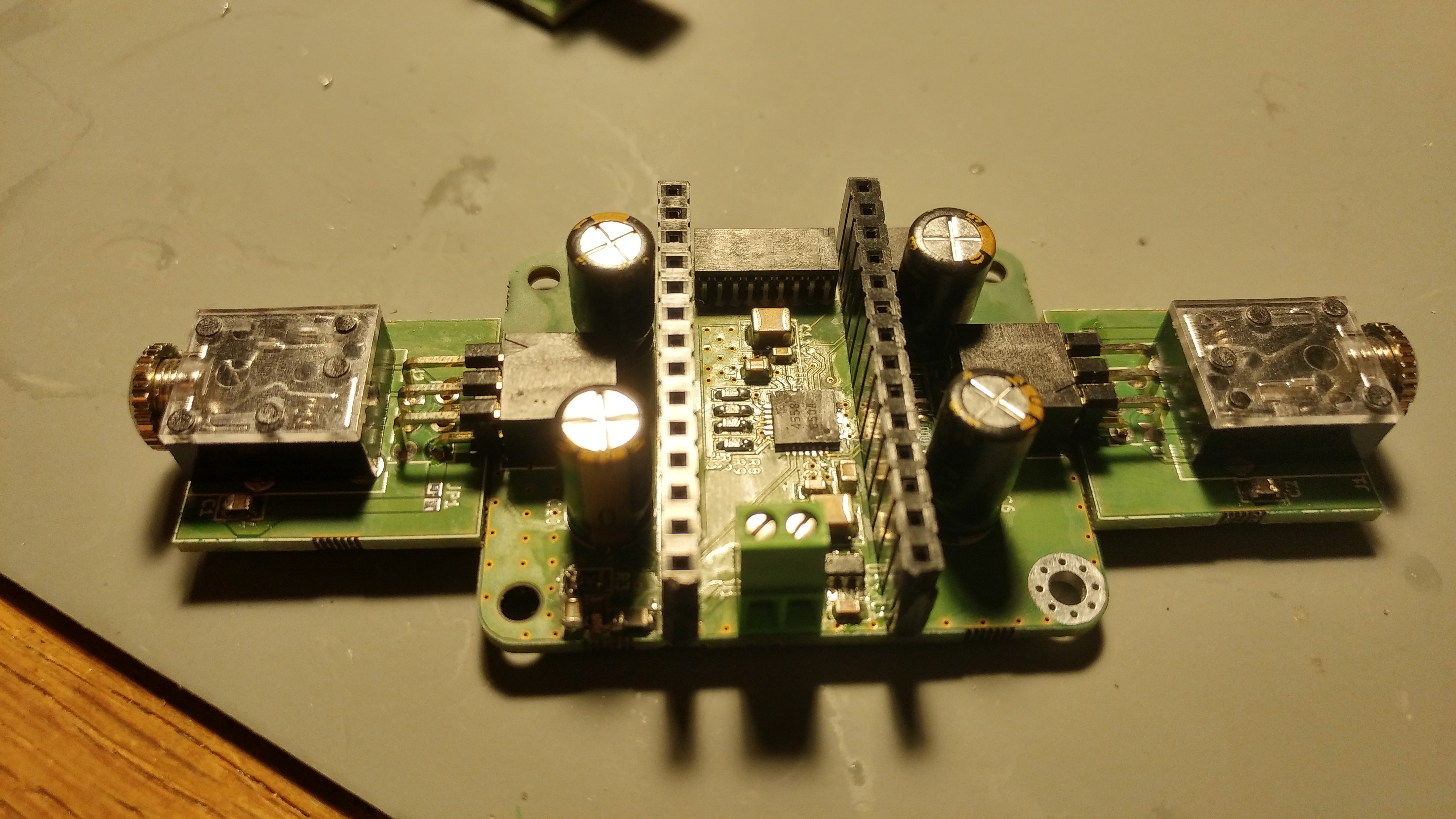
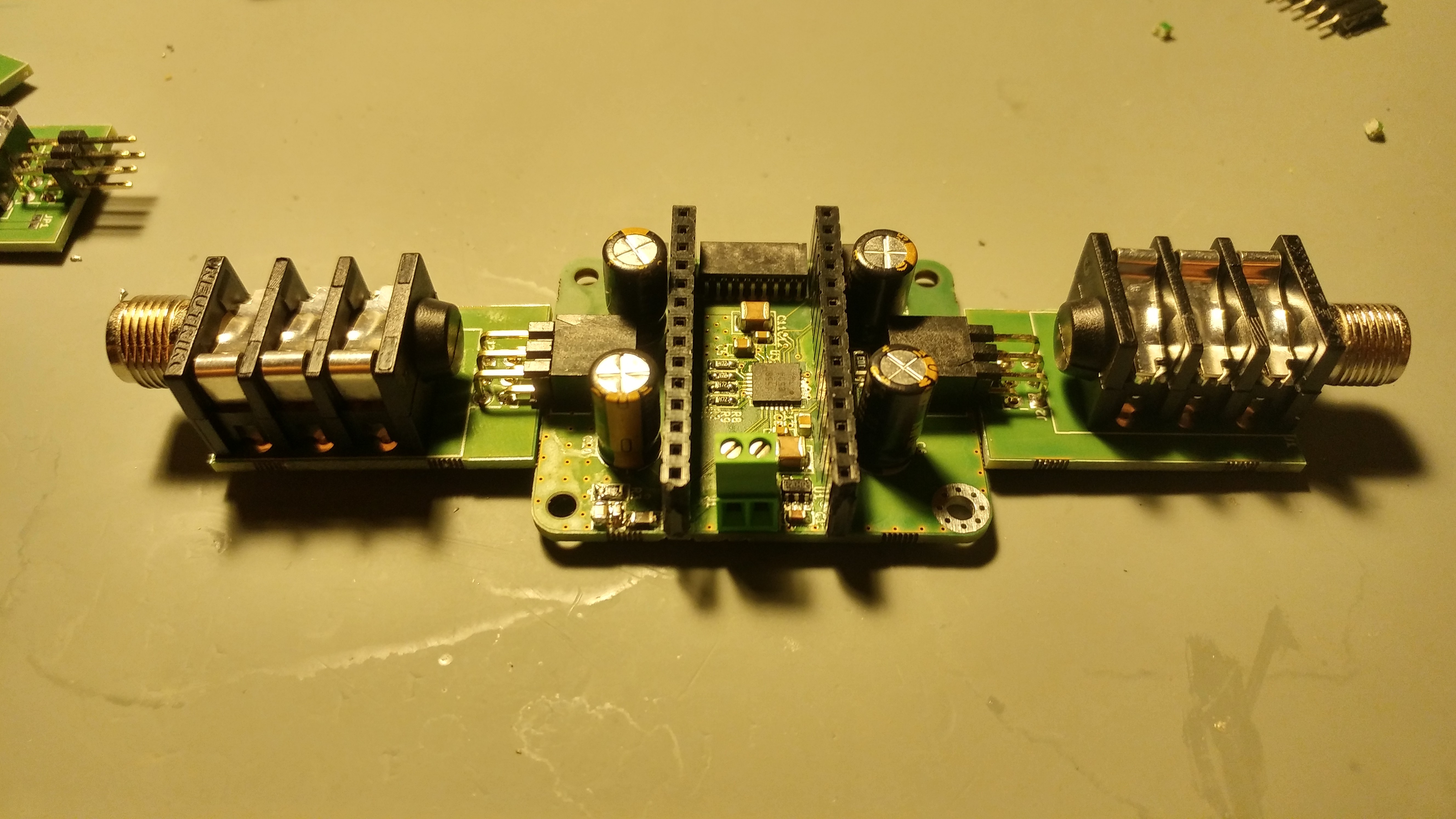
    I made the first CORE module and a set of IN MINI connectors with the ChipQuik paste just fine, here they are:


    The paste is ok, but it does not stick very well to the pads and it keeps oozing out of the syringe even after you stop pushing the plunger. 

    The first CORE proto is fine (except for a spurious copper polygon on the bottom layer that accidentally shorted the power pins ... OOPS :D luckily I only had to scrape some copper away and that's it), the jacks are pretty straightforward.

    THEN: I decided to use the Pb-free paste for the rest of the protos, that is another CORE module plus the PSU, IN and OUT modules. The paste is a beauty to dispens, it sticks perfectly on the pads and does not ooze, allowing a precision job to be done really easily.

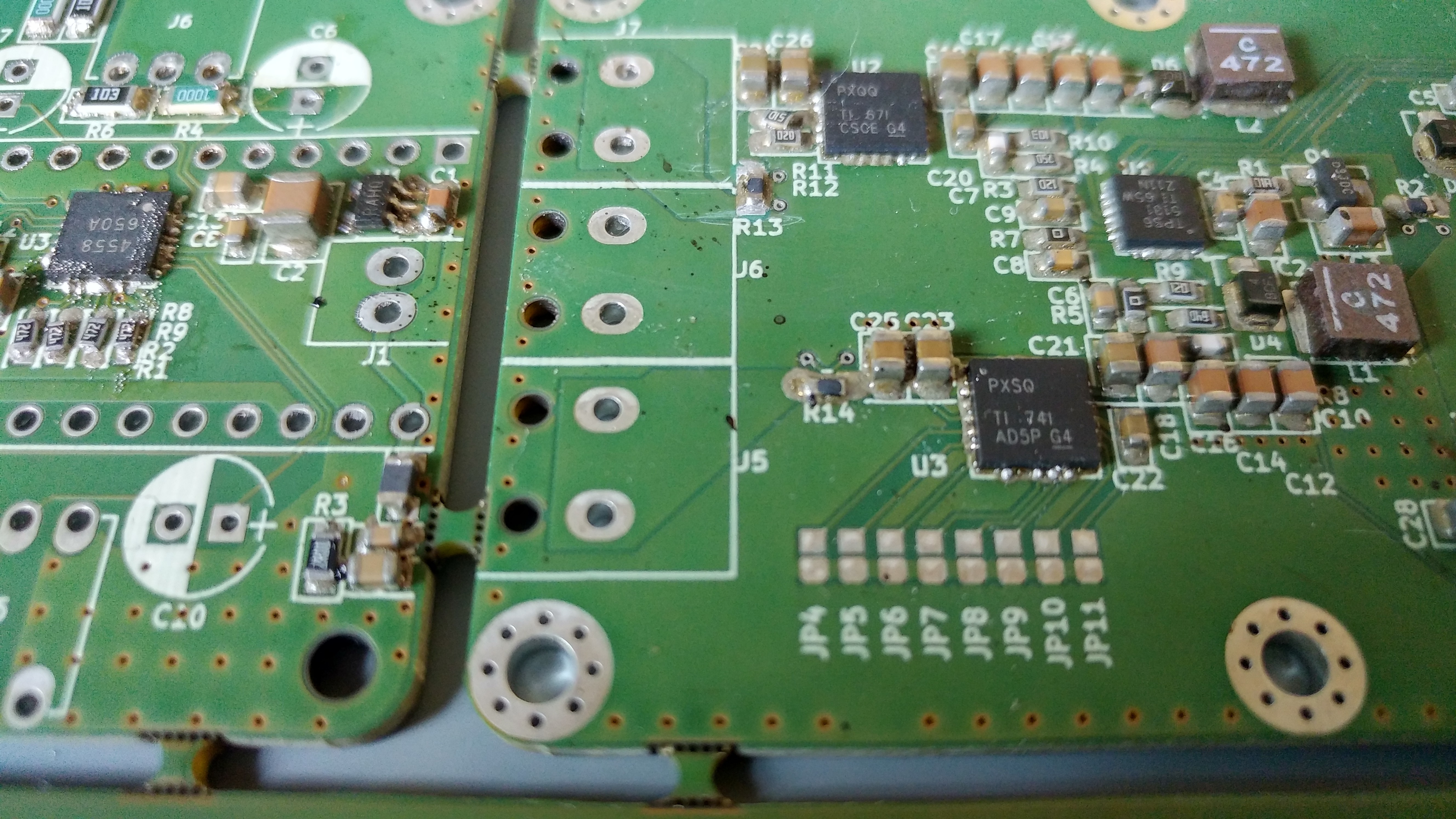
    The downside? IT NEVER MELTS. Take a look:

    (oh, in the last picture you can see that the package for the TPSA6120A2 is smaller than it should be but luckily the 10 useful pins could match up with the fooprint)

    I literally put the board through 4 cycles of reflowing in the oven.

    I first used a standard profile, then a longer and higher temperature one twice, then a custom made with even longer and higher temperatures... nothing. The paste is half-melted half-not, the board is literally baked. In an attempt to recover this situtation I turned on the manual setting on my oven to try to keep the temperature even higher for a longer period... the only result I got is that a capacitor exploded, the other 3 remaining electrolytics are swollen and ready to explode at any time, and most probably all the components on the board are useless by now. 

    The thing is that I could not even get this solder paste to melt with my iron nor with my hot air gun. I seriously put the tip of the iron to more than 300 celsius but the paste JUST. WON'T. MELT.

    The only time I got one component properly soldered was when I literally put the hot air gun at 320 celsius with the nozzle at 2 mm distance from the component. I know I can't try this technique on all the components because if they're not broken by now (I highly doubt it) they'll surely be after this treatment.

    So... yeah, a lot of cash just went down the drain. This sets me back a lot in terms of money and time, because I should have spent this week testing the protos but I ended up sad with no money to invest right now and with no protos to test :( 

    I'm going to order the components to make another panel in the next days, in the meanwhile I'll solve some software issues that does not let me use the CORE module properly (there's something in the AudioOutputI2S object of the Teensy Audio Library that crashes I2C communication with the AK4558).

    More to come.

    Michele

  • #8 - PCBs are in, components are on their way + crowdfunding plans

    Michele Perla09/19/2017 at 10:44 0 comments

    Quick update:

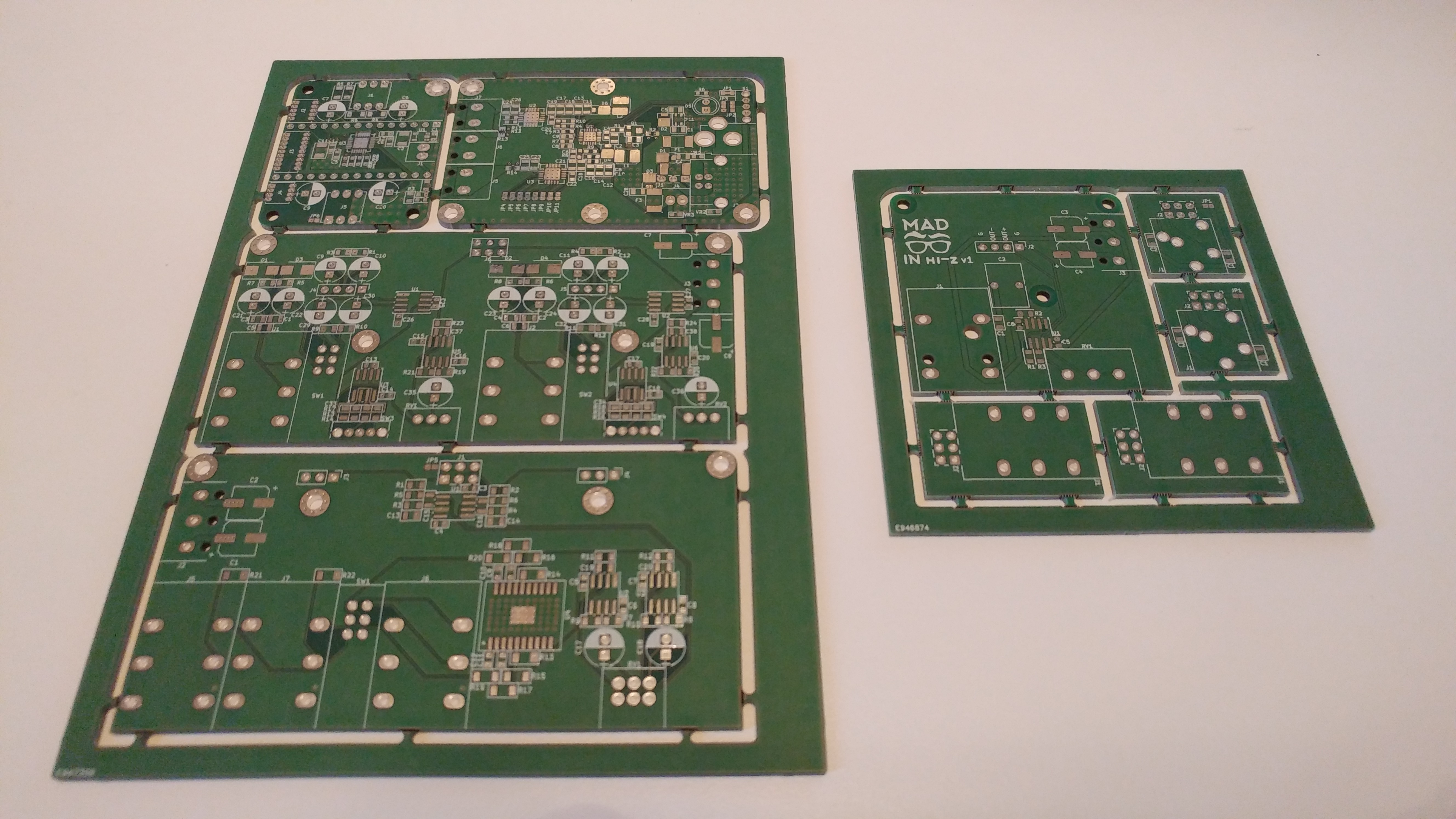
    I received the PCBs for the modules I've developed until now; Eurocircuits did an amazing job. 

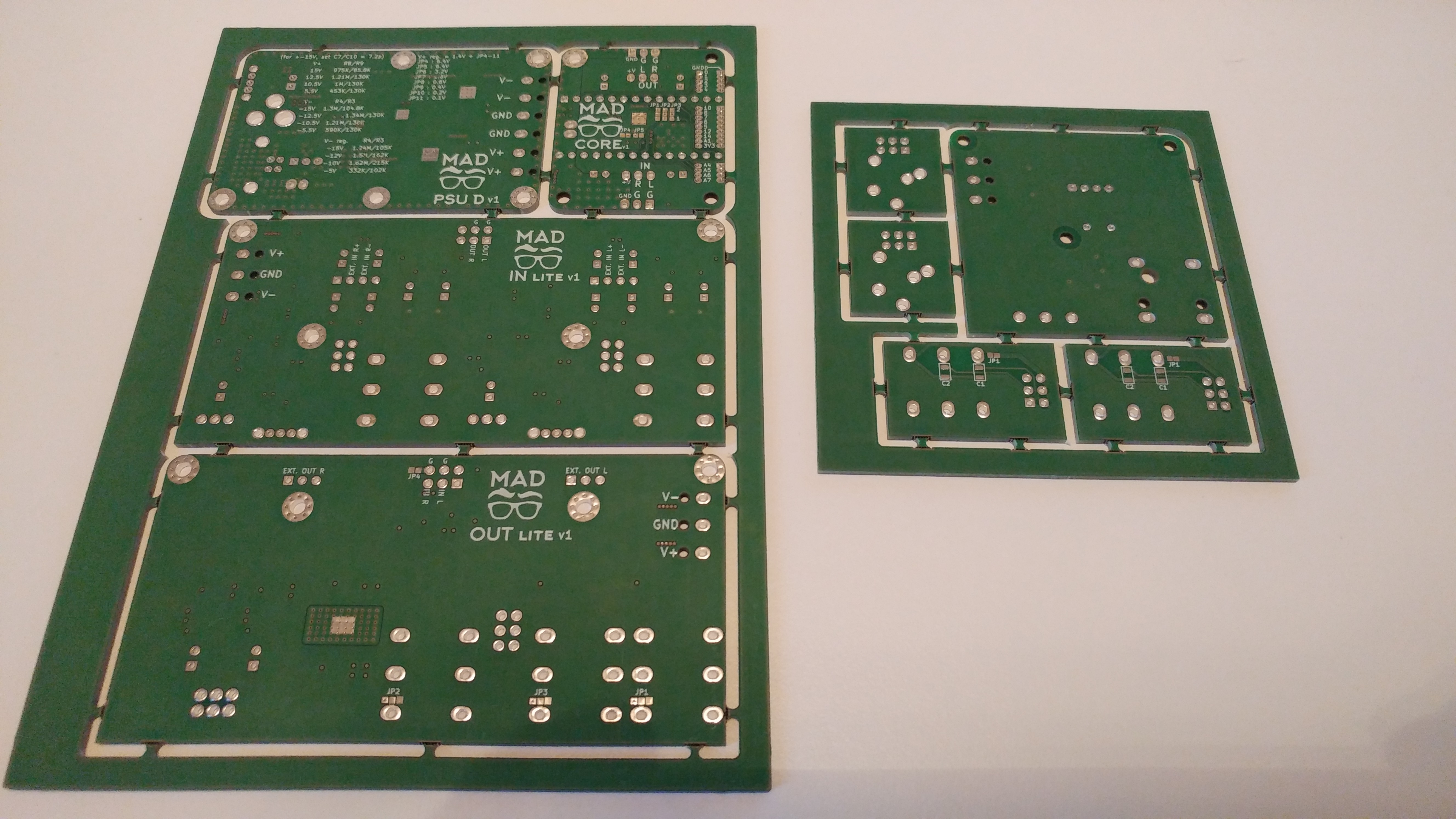
    Here's the front of the panels:

    And here's the back:

    I also received the AK4558ENs from Digikey, as well as a Xilinx XC9572xl development board to test the IOAPEX functionality while waiting for the components to be shipped.

    Finally, I also got a reflow oven to make the soldering job much easier and faster. I can't wait to solder these beauties and test them thoroughly.

    I can only afford to make one full kit plus an extra CORE module, just to show that the 4 ins 4 outs functionality is there. 

    As soon as I got this first version tested, and as soon as I know the real SNR, THD+N specs of the IN and OUT modules I'll publish them. The simulations show amazing performance at 1KHz (way above the AK4558 specs) but the real world is a different thing.

    About the crowdfunding: I have the intention of starting the campagin ASAP, that means as soon as I got the protos done; also I have the intention of starting one campaign just for the CORE module because I really don't think I can handle a campaign with 9 boards to produce, it would get messy with the boards, it would get messy financially, it would get messy bureaucratically... BUT! I'd really like to make other campaigns soon after the first one to get the other boards out on the market.

    Cheers,

    Mick

  • #7 - Best Product deadline update

    Michele Perla07/24/2017 at 15:04 0 comments

    Quick update before the Best Product deadline:

    The CORE module is done (at least on paper), the PSU module is almost done (I got to find a nice position for the power connectors for the submodules), while the INPUT and OUTPUT modules are yet under schematic review. I am also thinking of making a single supply version of the analog interfaces modules, but not now.

    About the business plan required for the deadline: I have no idea how to make one. I've seen online that to make a proper one I should basically be ready for production, which is totally not the case since I still have to order my first batch of prototypes. Nonetheless, I have a plan in my mind that it's quite easy to follow and I hope it will be counted as a "business plan" at least for the sake of the contest (I know I have to make a proper one since I got to make a crowdfunding):

    My plan is to start making the CORE module through a crowdfunding campaign, to sell it as a higher quality alternative to the Teensy Audio Board; ideally I will offer several modules on the campaign, to give the users several donation incentives (e.g. : first incentive is for one CORE module, second incentive is for one CORE module + PSU + simple analog IO interface, third incentive is for one CORE module + PSU + simple analog IO + pro level analog IO, fourth incentive is for 2 CORE modules + PSU etc etc), but I must be realistic and accept the fact that I may not be able to develop all these modules in time for a campaign.

    As soon as the campaign ends I will keep producing boards either in house (if the demand will not be huge) or through external sources. To produce the boards in house I will need to buy some tools (namely: pick n place, reflow oven). 

    Also, when the campaign ends I will spend the next 6 months to provide support for the modules produced during the campaign, through the means of a forum of some sort.

    After the first 6 months, I will reduce the support time (in hope that 6 months of user base support will cover 99% of the necessary support information for everyone) and resume development of new modules (IOAPEX, PRO PSU, single supply analog IO interface, etc.).

    This will eventually reiterate.

    In a nutshell my idea of business is as follow:

    -Make some MATT modules prototypes

    -Make a crowdfunding to kickstart production of said modules

    -At end of campaign, provide 6 months of support to said modules (or less if most of the support information has already been covered) while continuing production (in house or external fabs)

    -When support phase is over, I will start development of new MATT modules

    -After 6 months of prototyping and preparation, make a new crowdfunding campaign to kickstart production of new MATT modules

    - Reiterate

    I am also considering hiring someone in the future, either to help me with in house production, or to help me with the crowdfunding campaign (probably both). I will also have to invest on marketing/advertisement to make a proper campaign.

  • #6 - Progress so far

    Michele Perla07/01/2017 at 14:13 0 comments

    Hey there,

    quick updates on the project:

    • after talking to a friend, I decided to use the AK4558EN codec instead of the AK4621EF because I already worked with it, I already made support code for it for the Teensy, it has single ended inputs and outputs making the analog interfaces design way easier and cheaper (less opamps = less price), and also it uses an I2C control interface instead of a SPI one, hence reducing the max. theoretical number of devices using the SPI bus in a complete MATT powered system
    • I decided to use the ARCHER (M50-32xxx) series of Harwin Connectors for all board-to-board connections; their dual row 1.27mm spacing connectors are perfect for my case, since I have connectors right under the Teensy these take half of the space, giving me a lot of freedom for component placement
    • I decided to remove some features from the CORE module, making it more barebones and compact; these features are going to be moved on external modules to let users chose which features they need and which features they don't need

    I am almost done with the layout of the CORE module, then I'll move on to the PSU and to the analog IO interfaces, then I'll start ordering some protos.

    As soon as I finish a module I'll update GitHub and here accordingly, with 3D renderings of the PCBs as well.

  • #5 - The Licences

    Michele Perla05/01/2017 at 13:59 0 comments

    MATT is going to be a commercial project.

    My goal is to make a crowdfunding out of this and try to earn a living by producing MATT and future modules for it.

    Schematics and PCB layouts of main modules

    Some parts of MATT's hardware will be delicate and will require careful PCB layout considerations, and to make my design easier through all the different supplies involved as well as to reduce noise in the analog domain due to interferences from digital traces, I will probably use more than 8 layers PCBs, which is not exactly affordable for everyone anyways. So I am thinking of not releasing the layouts, at least of the CORE.

    But I would release the schematics for reference, for anyone to hack around it.

    VHDL for IOAPEX

    I am also thinking of releasing the binary for the Xilinx CPLD, but not the source of the VHDL. This may change in the future; also, for all the VHDL/Verilog hackers out there, a programming header will most probably be present on the final IOAPEX module, so if you want to upload your own code feel free :)

    Code

    All the code to drive all functionalities will be open source. Open sourcing the code is a must in order to give back something to the Teensy community, but also to enable users to develop all kinds of custom submodules.

    Submodules: the real deal

    I would like to keep the focus of users on the creation of new submodules, which are the real key element of this project.

    The base specs for modules, as well as barebones versions of modules, will be fully open source and open hardware.

    The analog IO modules could be made easily by using perfboard; eg. a JFET buffer for a guitar. I will use standard 0.1 inch headers wherever possible, and I will try to keep their spacing in 0.1 inch multiples. As long as the max. output value of the module respects the specs of the CORE onboard input module, anything goes.

    Same thing for the IOAPEX modules: the IOAPEX is in fact designed specifically to keep the external components to a minimum. As already explained, each type of sensor will require only 1 mux, and maybe a couple of passives. I will release base layouts for digital in only modules, digital out only modules, and analog in only modules.

    I was also thinking of making the easiest module, that is one module with one mux, a jumper to select its operation (analog, digital in, digital out), and then 16 plated thru holes to connect to anything an user would like to.

    Let's not forget that every submodule could be used with ANYTHING else, really. In the end these will just be muxes and switches. You want a simple button matrix to use with your Arduino? Get the first mulitplexer example sketch you can find online and plug your arduino to the module through its provided pin header and voilà

    Conclusions

    Some of MATT's design files will not be open, I know, but its key part will be fully open, giving the users simpler ways and tools to make custom and powerful audio solutions.

  • #4 - The Sub-modules

    Michele Perla05/01/2017 at 13:50 0 comments

    MATT will be composed of 3 main modules (CORE, POWER, IOAPEX), plus an ecosystem of submodules.

    Some of the submodules I will/would design are as follows.

    • CORE input modules:
      • mic/instrument preamp with opamps
      • mic/instrument preamp with vacuum tubes (using POWER)
      • RIAA phono preamp (stereo, it would take both inputs)
    • CORE output modules:
      • headphone preamp with opamps (stereo, it would take both outputs)
      • small speaker driver (1 or 2 W, mono)
      • big speaker driver (10-20 W, mono, using POWER)
    • IOAPEX modules:
      • 4x4 buttons matrix with LEDs
      • 4 channel mixer control module: each channel with 1 slider, 1 mute button, 1 solo button, 3 knobs for bass-mid-treble, and 4 LEDs for VU meter.
      • 4x4 FSR matrix
      • 3 octaves compact keyboards (maybe with FSRs?) with pitch-bend and modulation
    • POWER modules:
      • POE with Ethernet could be a separate module

    For the IOAPEX submodules, the limit is one's imagination. I was already thinking of making a Minimoog mockup control interface and plug it in the IOAPEX, or a Rebirth hardware clone... I would really love to bring something like that around as a demo :)

View all 13 project logs

Enjoy this project?

Share

Discussions

Bogdan Rădulescu wrote 04/30/2017 at 11:53 point

Sound like a great project. What do you think about using ESP32 as the core? It's way cheaper than Teensy 3.6 and it's pretty speedy.

  Are you sure? yes | no

Michele Perla wrote 04/30/2017 at 12:03 point

Hi Bogdan. Thanks for the support. I am thinking more about the Teensy because of the Audio Library support and for the community that keeps creating amazing audio projects with it; but if someone would like to use this board with any other chip that has I2S and SPI capabilities, good for him! The header on the board does not need to be necessarily populated with a Teensy 3.6 :) The source code for the configuration of the codec, as well as for the use of the IOAPEX module, will be open. If someone would later like to port it to other platforms they can, as long as the platform of choice has a DMA controller, because I would make use of that for better performance

  Are you sure? yes | no

Similar Projects

Does this project spark your interest?

Become a member to follow this project and never miss any updates