-
Project is Cancelled - I'm Done
05/27/2017 at 03:19 • 0 commentsReason 1:
Simply not enough energy in the super capacitors. Although it seems like there would be enough for at least a few decent stop starts, the internal boost converters and the poor efficiency of the DC motor and mechanical drive train on the bicycle just sap too much of the energy away from useful work. Effectively, I seem to get one complete start up to full speed and then that's it - It takes another 15 minutes to get one more.
Reasons 2-100:
Mechanical alignment of the motor and chain. If it decides to slip off one more time I'm going to hammer it into a tightly packed cube - It's driving me crazy and I'll have no more of it.
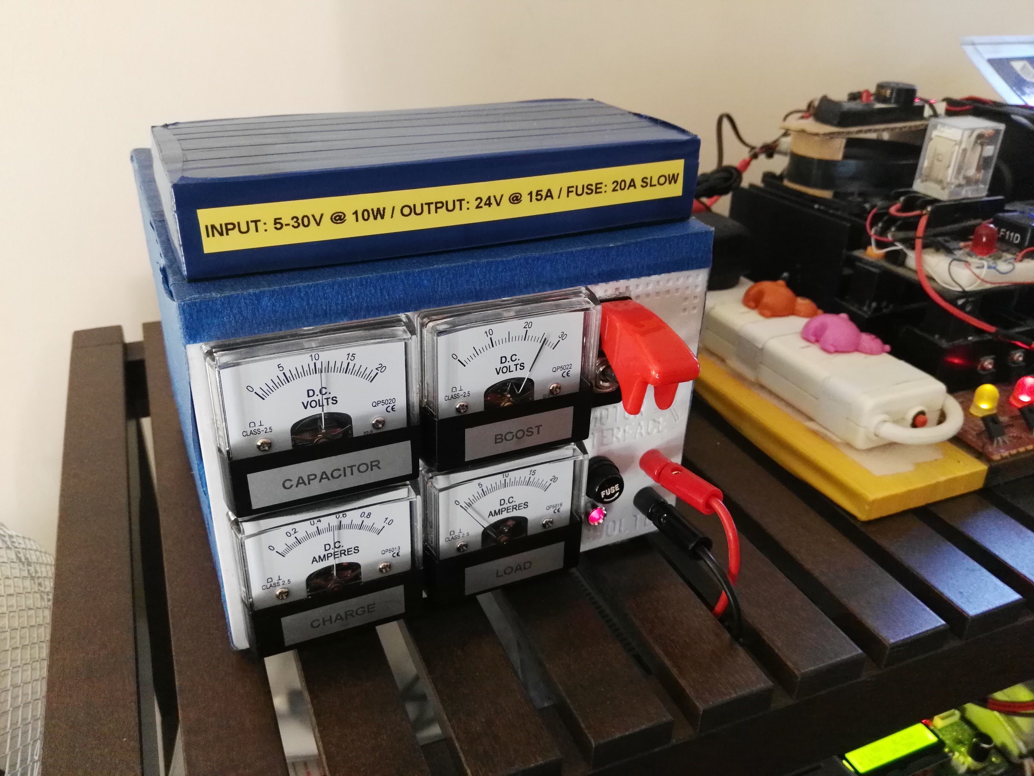
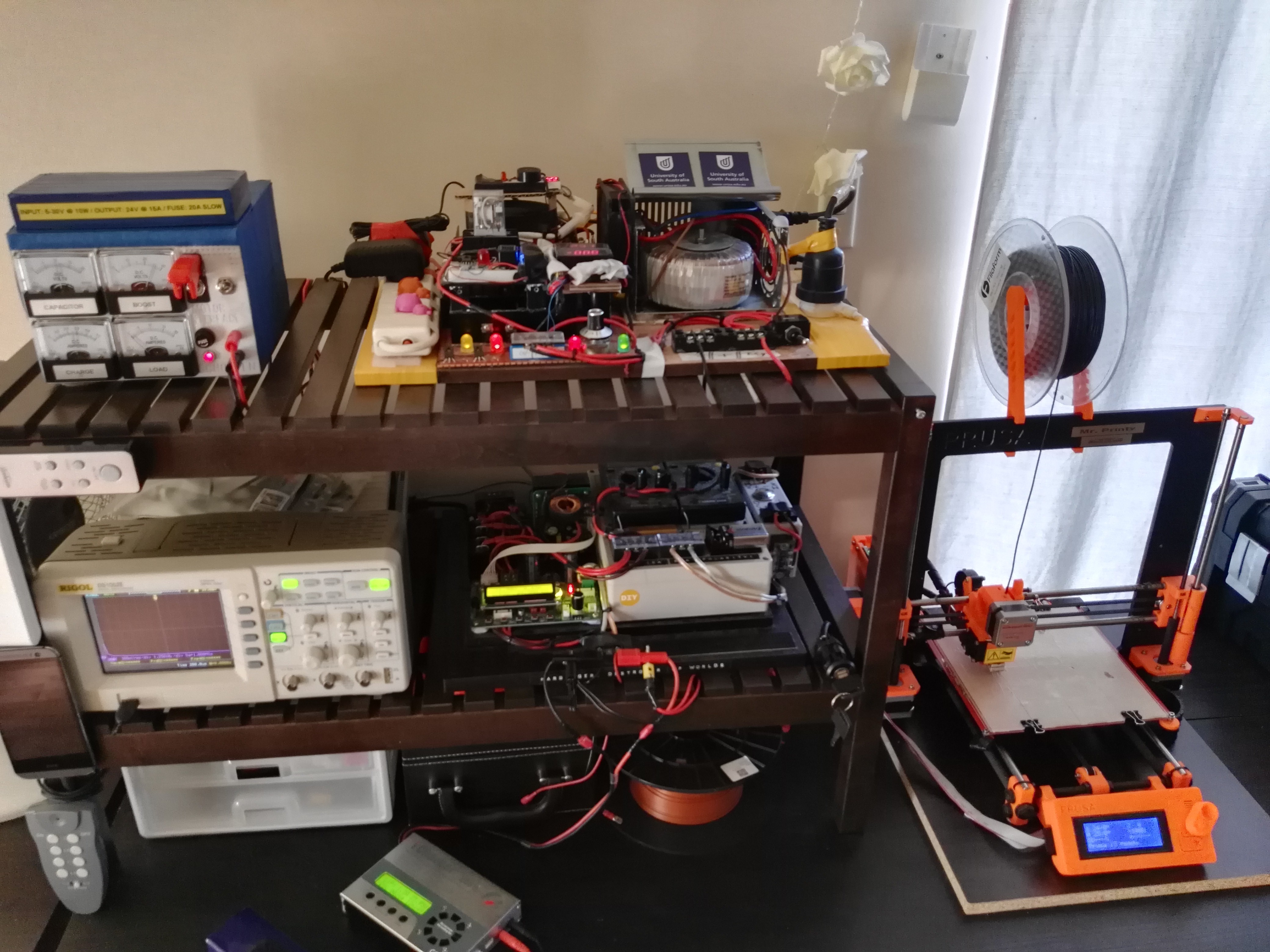
Eventually, I did find an extremely effective role for the super capacitor bank which was totally unexpected. This new role is a 3D printer backup power supply for electrical grid blackouts lasting less than 20 seconds. My 3D printer requires around 100 watts when using the heated bed, which suits the super capacitors' energy capacities nicely.
![]()
![]()
Super caps and another power supply connect in parallel (diodes) to a DC/DC converter that power the 3D printer.
I'll never be touching another project with such a large mechanical component again.
-
Change of Bicycle and Completion of the Hardware
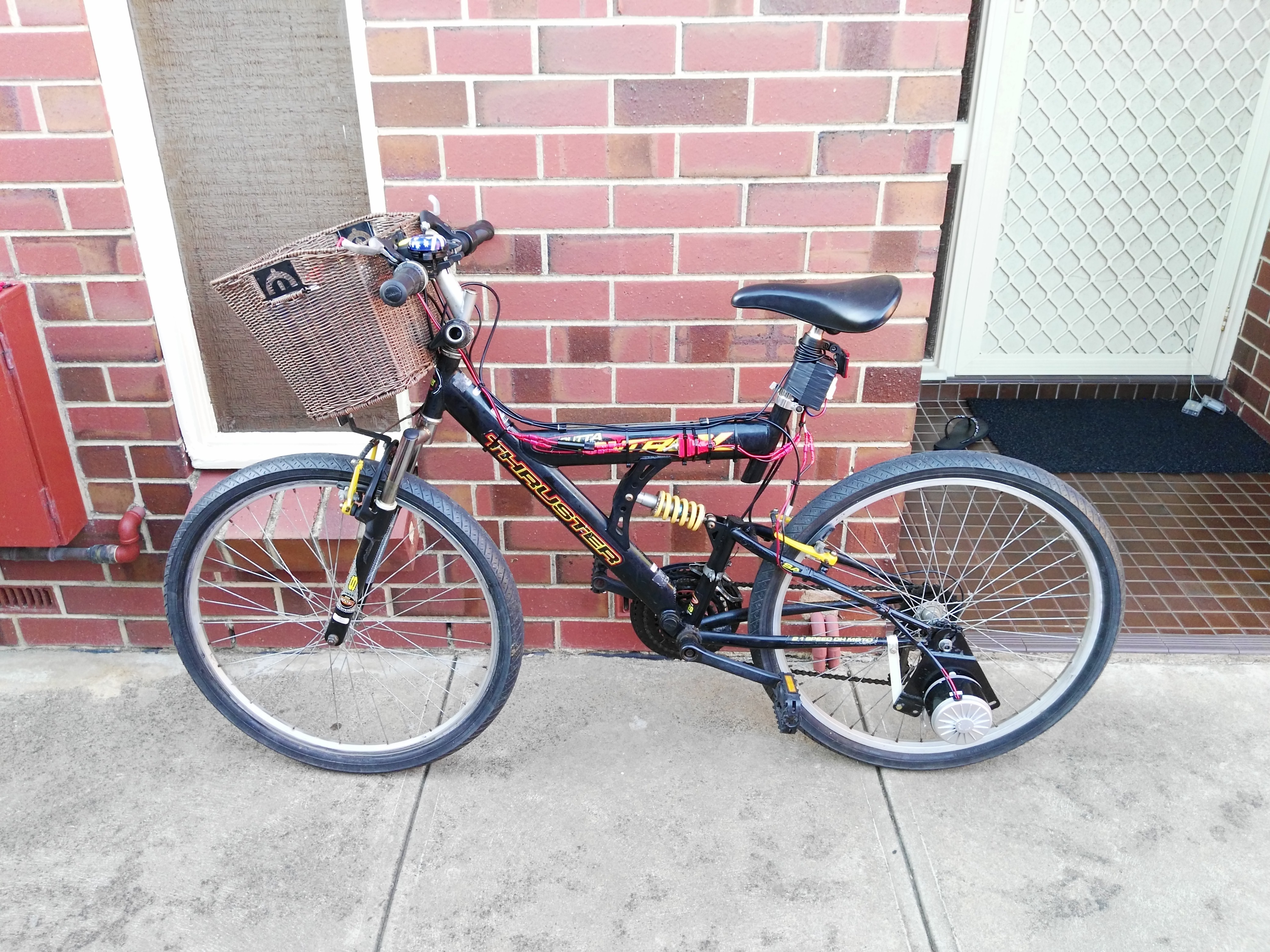
05/14/2017 at 04:23 • 0 commentsThere has been a change in bicycle due to mounting issues, which led me to use my old childhood bike from my parents house:
![]()
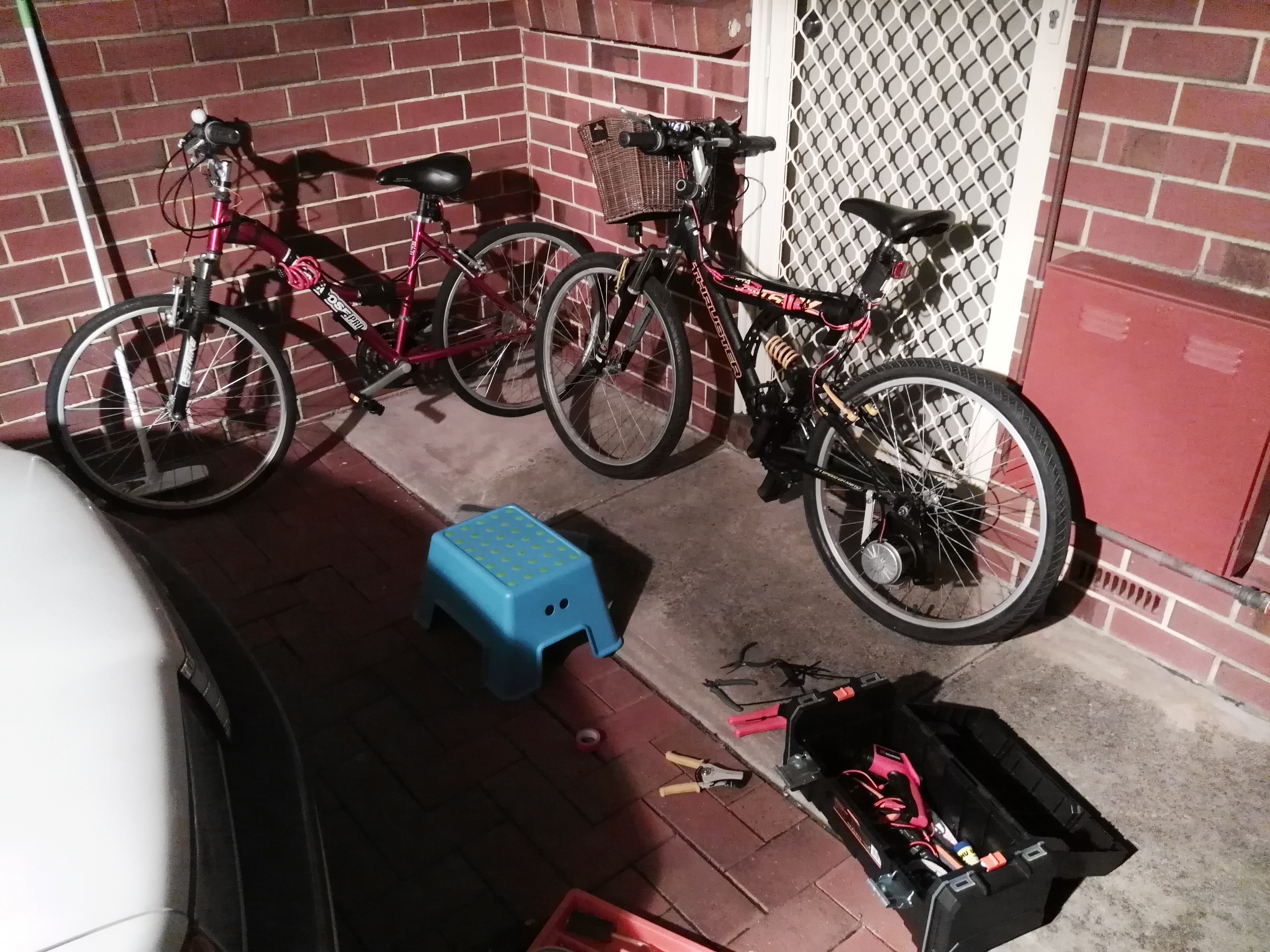
Working on the change over last night:
![]()
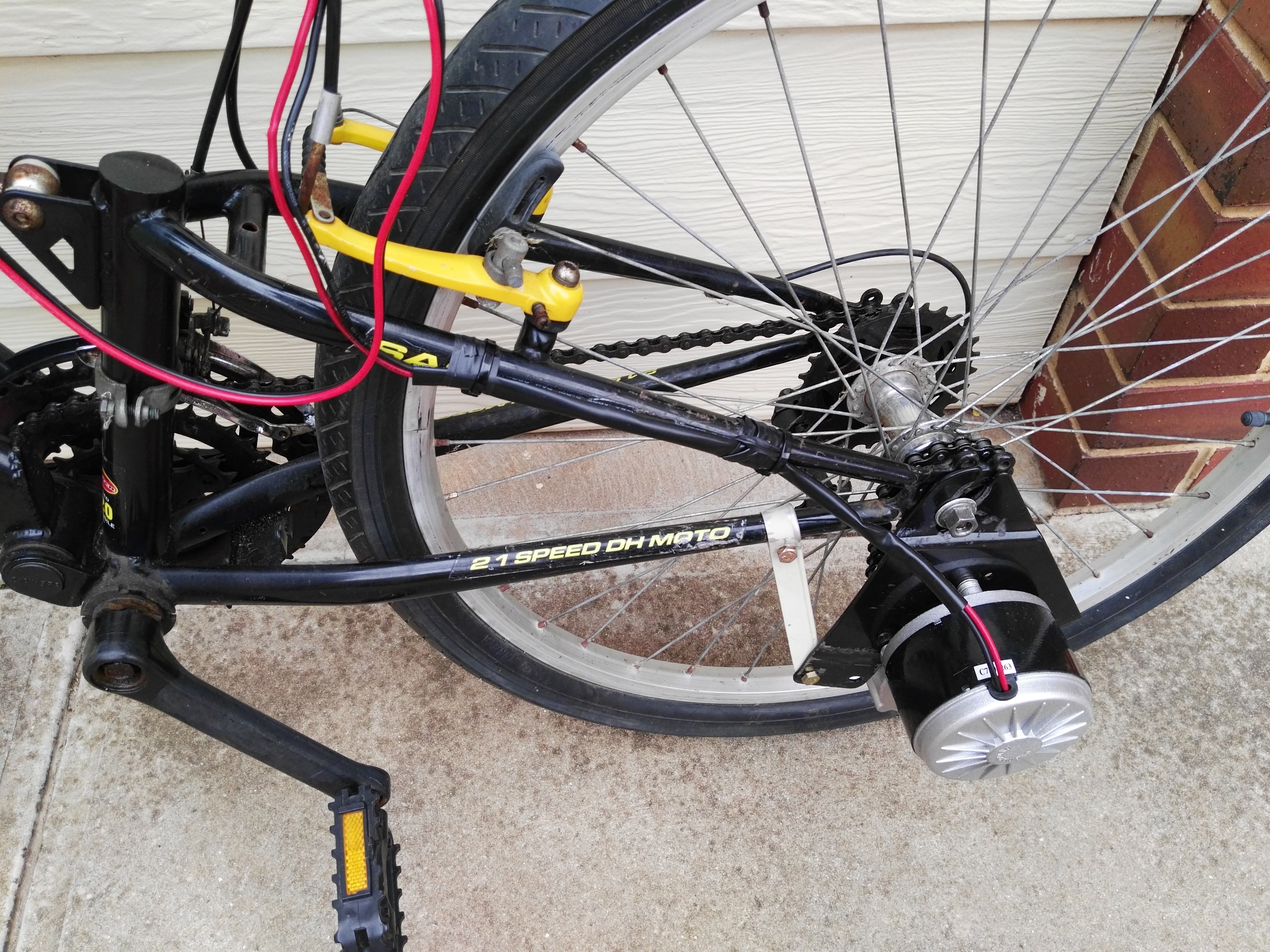
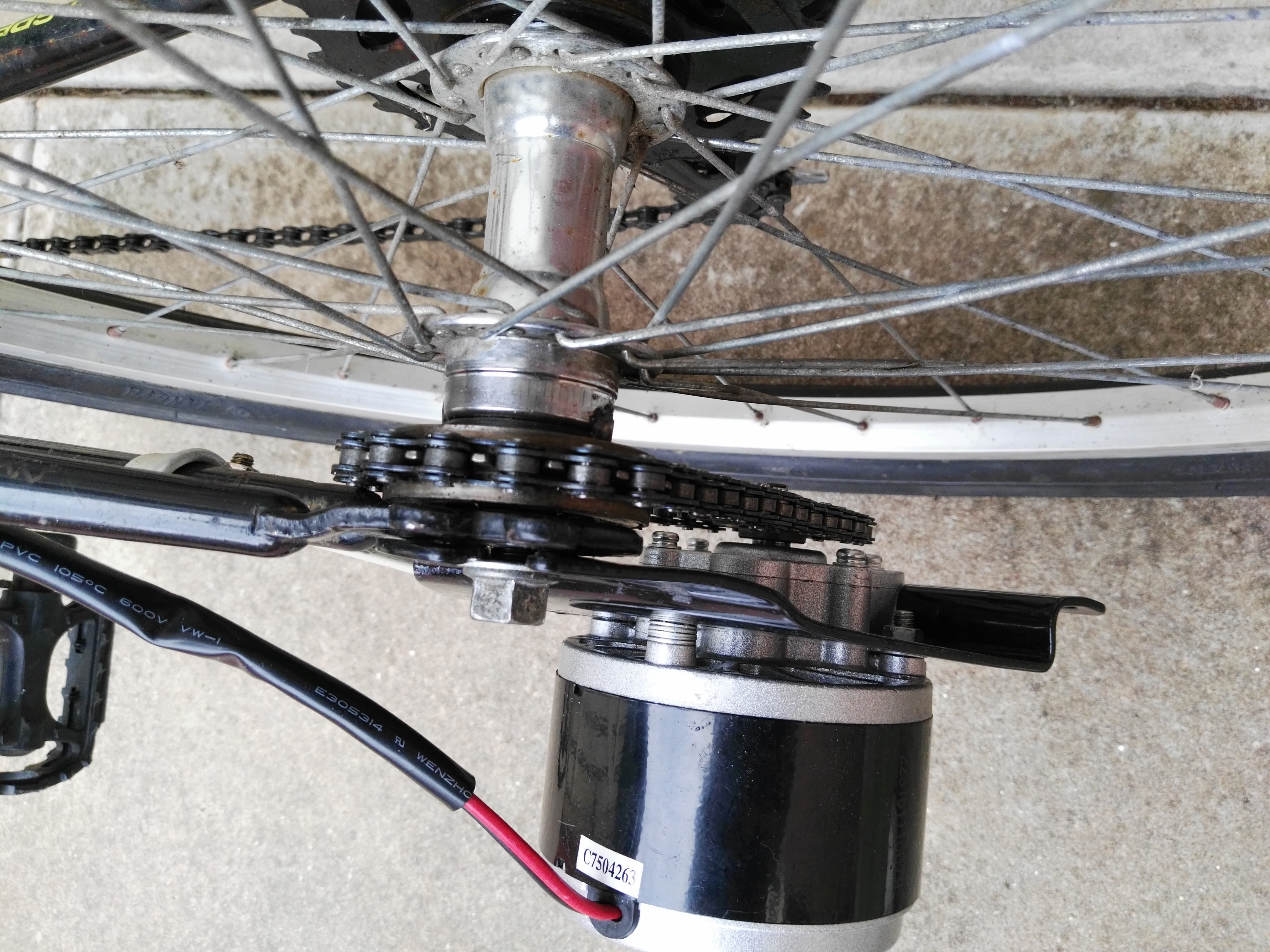
The motor has been successfully mounted/welded on. This was an extremely tedious process that I would care NOT to repeat.
![]()
Coupled through a separate chain, the motor can easily change its gear ratio by swapping out its cog connected to the chain. Practically though, this is not going to happen any time soon.
![]()
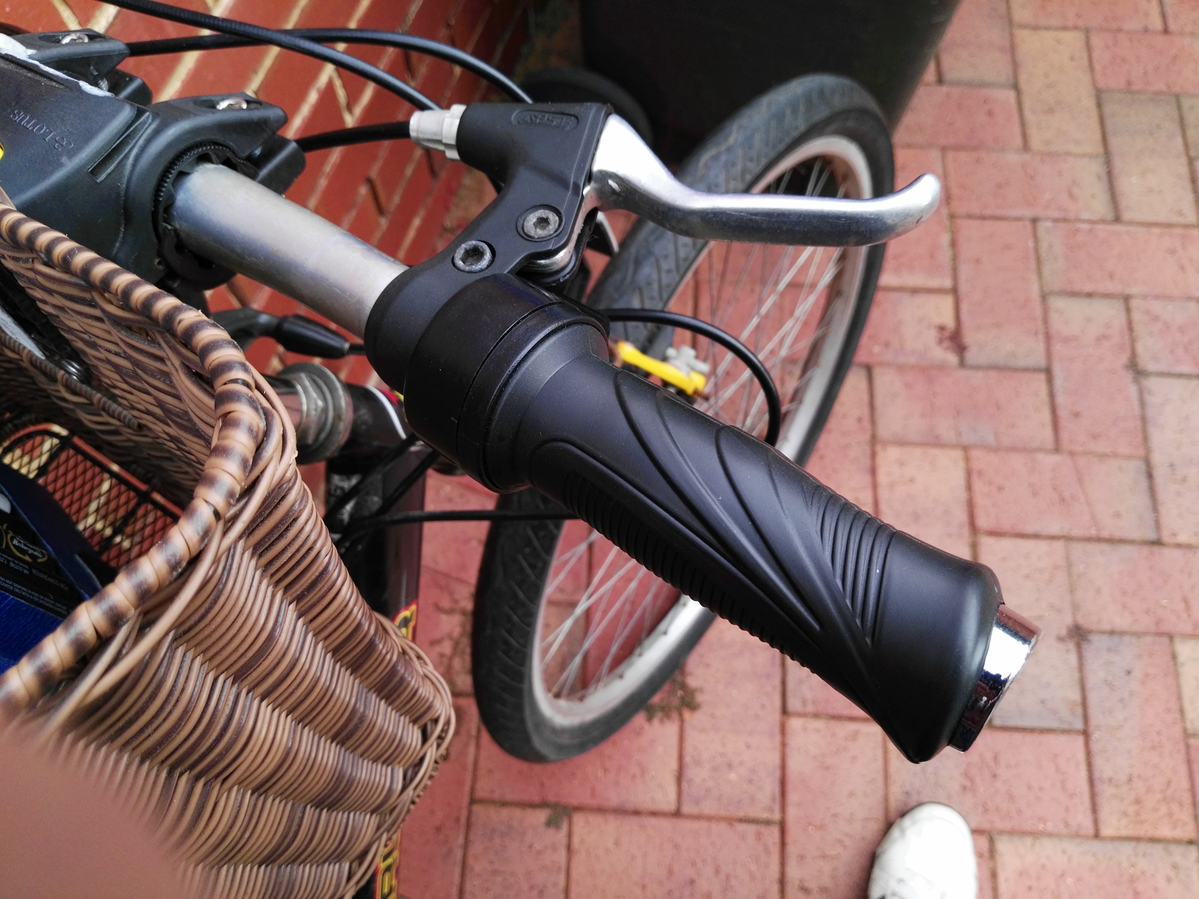
The throttle control is working great and there are no problems whatsoever.
![]()
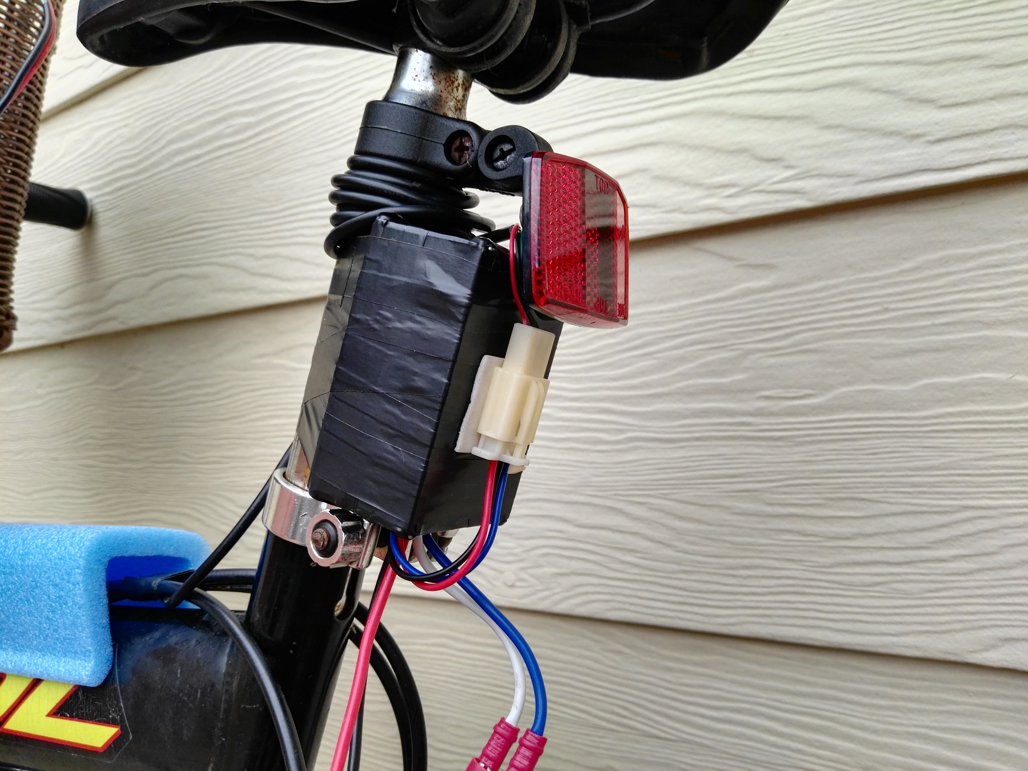
The DC-DC converter is mounted directly under the seating. Water proof for the most part, it fits in snugly. However, I did confirm that it is NOT a true DC-DC converter. It has no inductive output filter and no output capacitor. It essentially applies a variable duty cycle (throttle control) square waveform voltage directly across the DC motor. Although this still supplies the correct "average" voltage to the motor (e.g. 50%), the back emf does not follow the square wave. The difference in voltage is dumped across the winding resistance when the motor is pulsed.
Effectively, this DC-DC converter acts as a linear regulator, but dumps the dissipated heat into the motor. This was confirmed through a harsh test ride with a battery (the DC-DC converter was cold and the motor was burning to the touch.
![]()
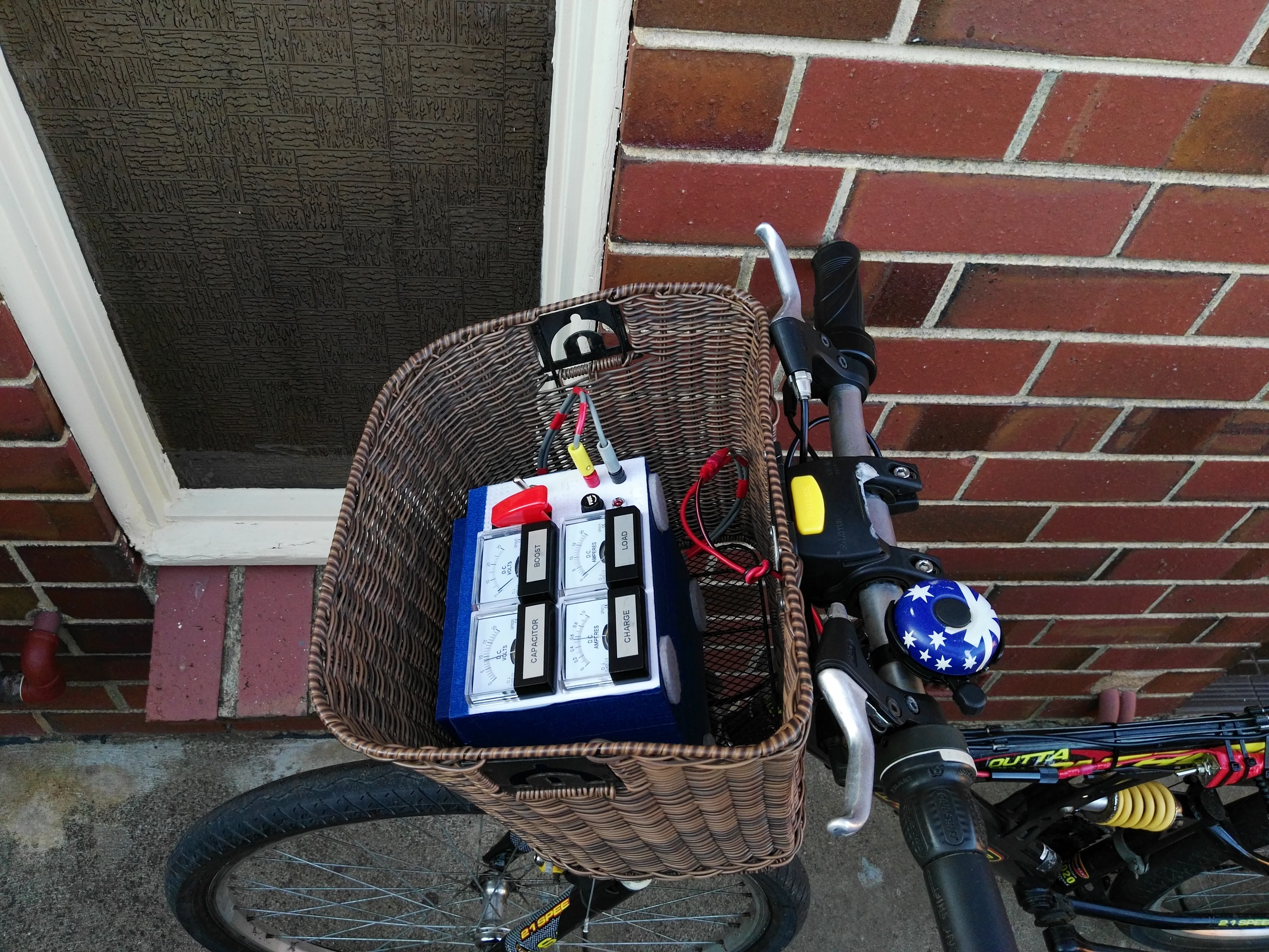
Next we can see the super capacitor in the fabulous basket:
![]()
Unfortunately, there is a harsh truth to the use of super capacitors in this project:
There just isn't enough energy storage.
Below is a video of just how fast the 24V stall current of the DC motor chews through the stored energy in the super capacitors.
I'll consider adding an inductor and flyback diode to the DC-DC converter of the bicycle to increase the efficiency, but it's not looking good.
Regardless, next up is a test drive with the super caps to the local store.
-
Quick Update
04/26/2017 at 14:01 • 0 commentsMaking some progress with the motor, it is now mounted successfully! Pictures and details to come soon.
-
Motor Mounting Difficulties
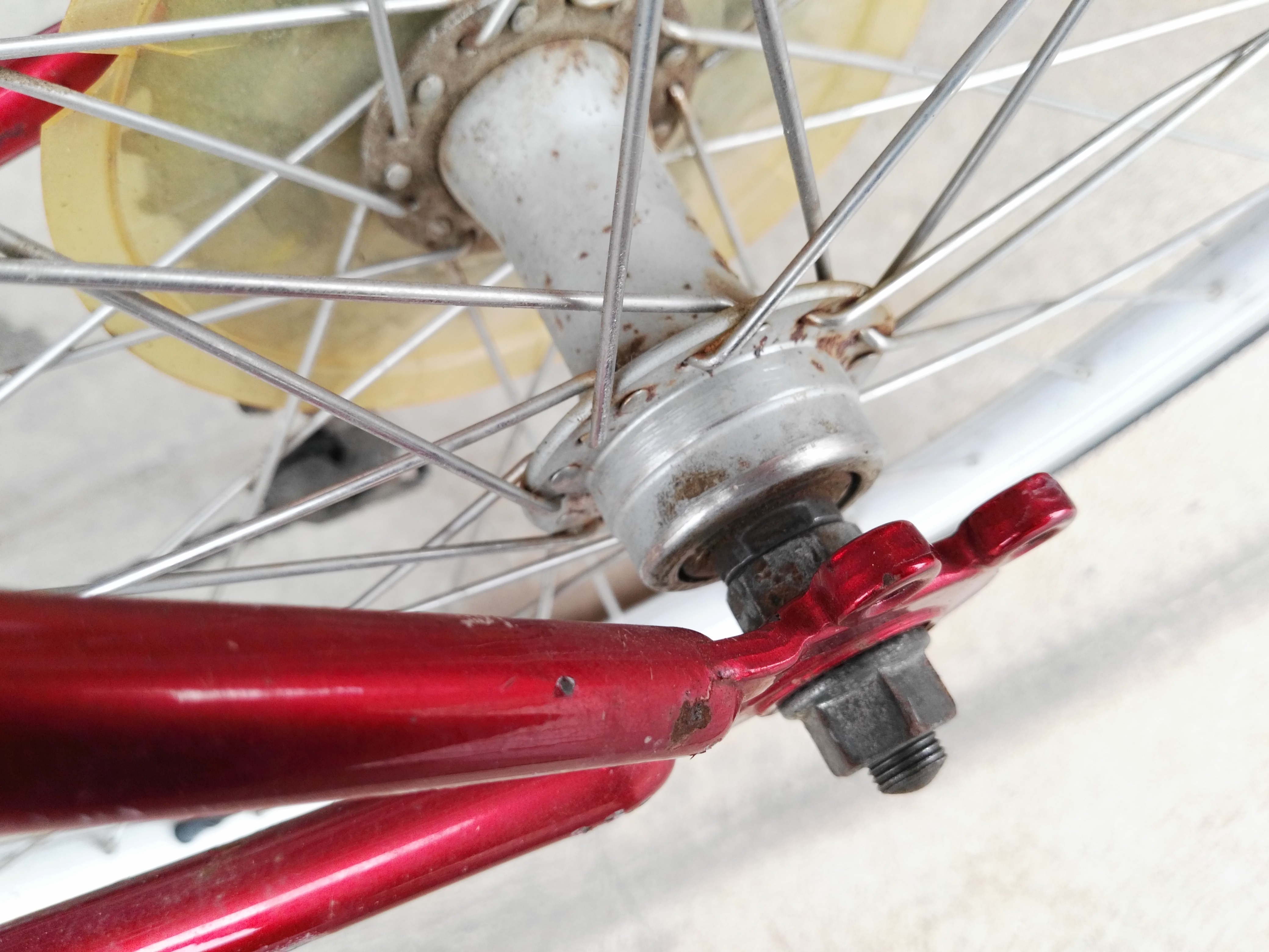
04/25/2017 at 05:55 • 0 commentsMounting the motor to the bicycle wheel is proving difficult, particularly due to the ratcheted gear that is supposed to thread to the wheel hub. There is no thread on either of my bicycles wheels and after considering the problem for some time we have decided to use some welding.
The ratcheted gear that came with the kit:
The part of the wheel that is supposed to apparently be threaded:
![]()
Getting some help making a weld from my Dad and one of his friends (this is the first time I have actually seen welding up close):
Needless the say, the mechanical part of this project (though simple) is taking a lot longer than expected!
-
DC-DC Converter Ready
04/23/2017 at 12:50 • 0 commentsTook some time today to focus on preparing the DC-DC converter for the bicycle.
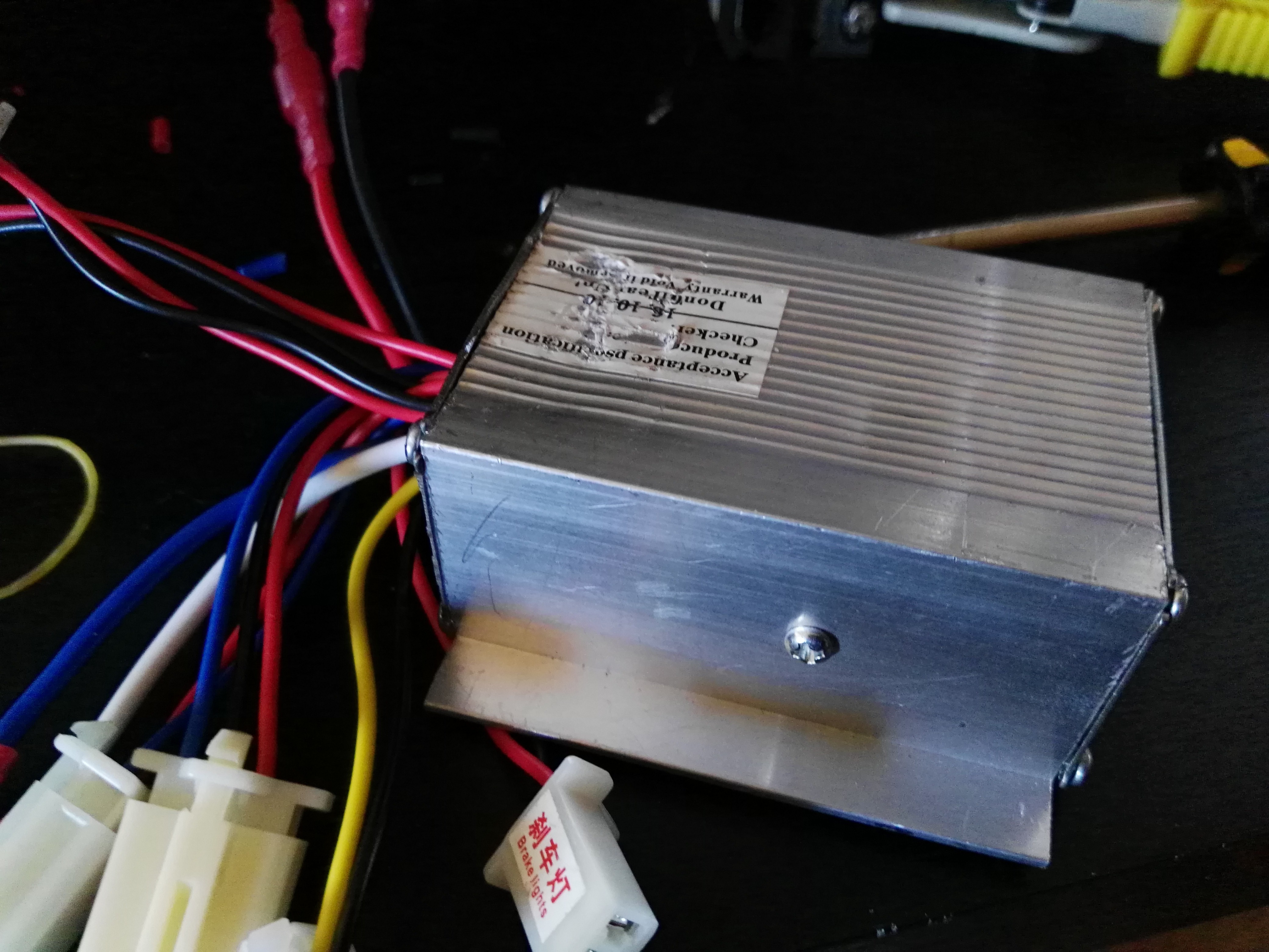
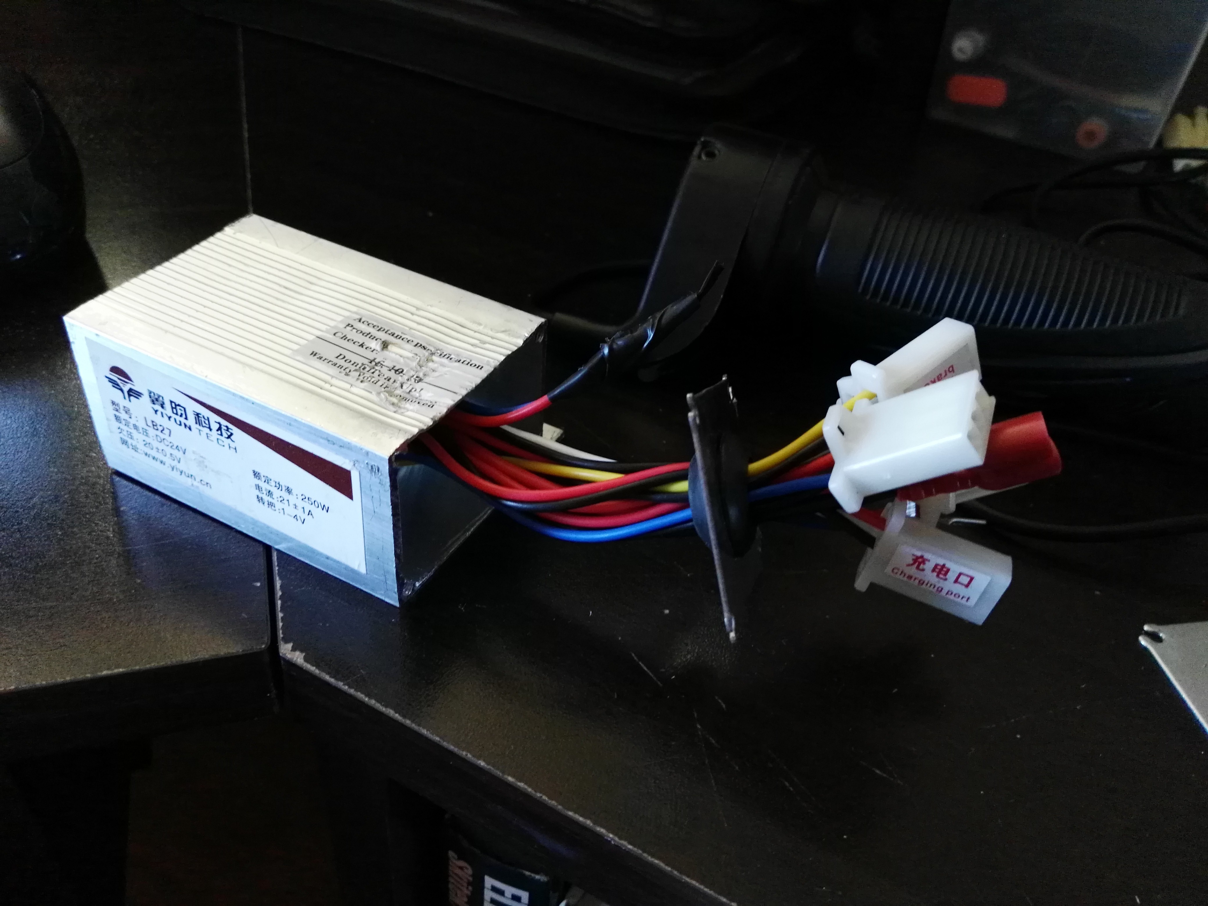
It has a multitude of inputs and outputs, all relating to the operation of a "standard" electric bicycle. These features include a battery charging port, brake notification in, brake lights out, headlights, key start, battery in, motor out and throttle control:
![]()
![]()
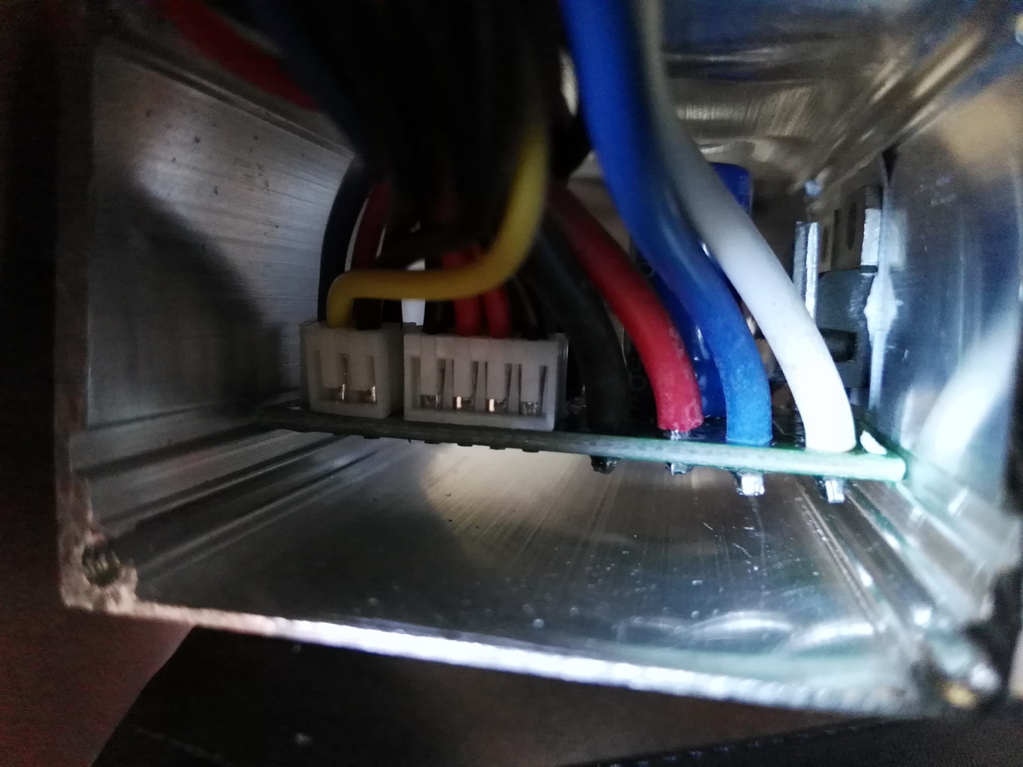
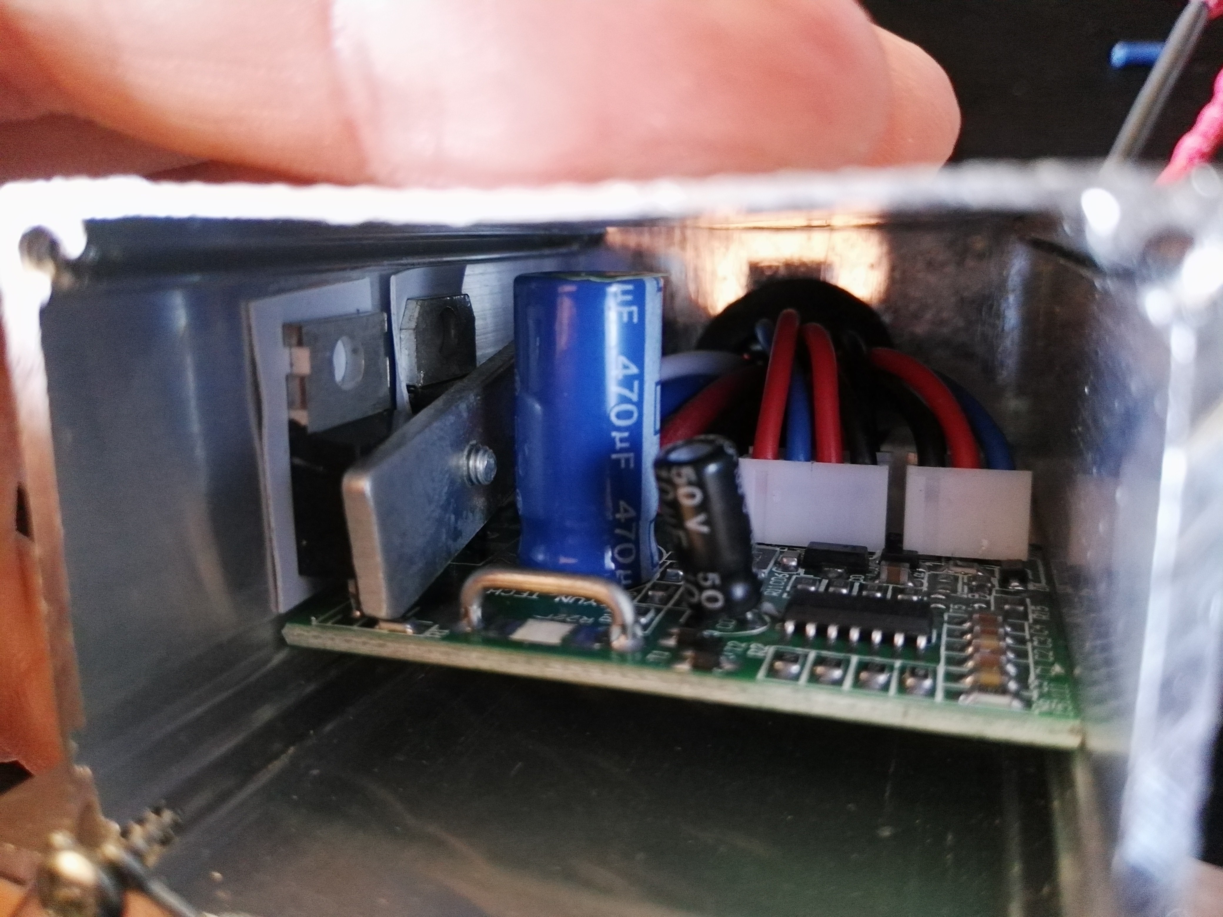
Taking a peak at the other side it seems to be a standard DC-DC buck converter with a single transistor and a flywheel diode.
![]()
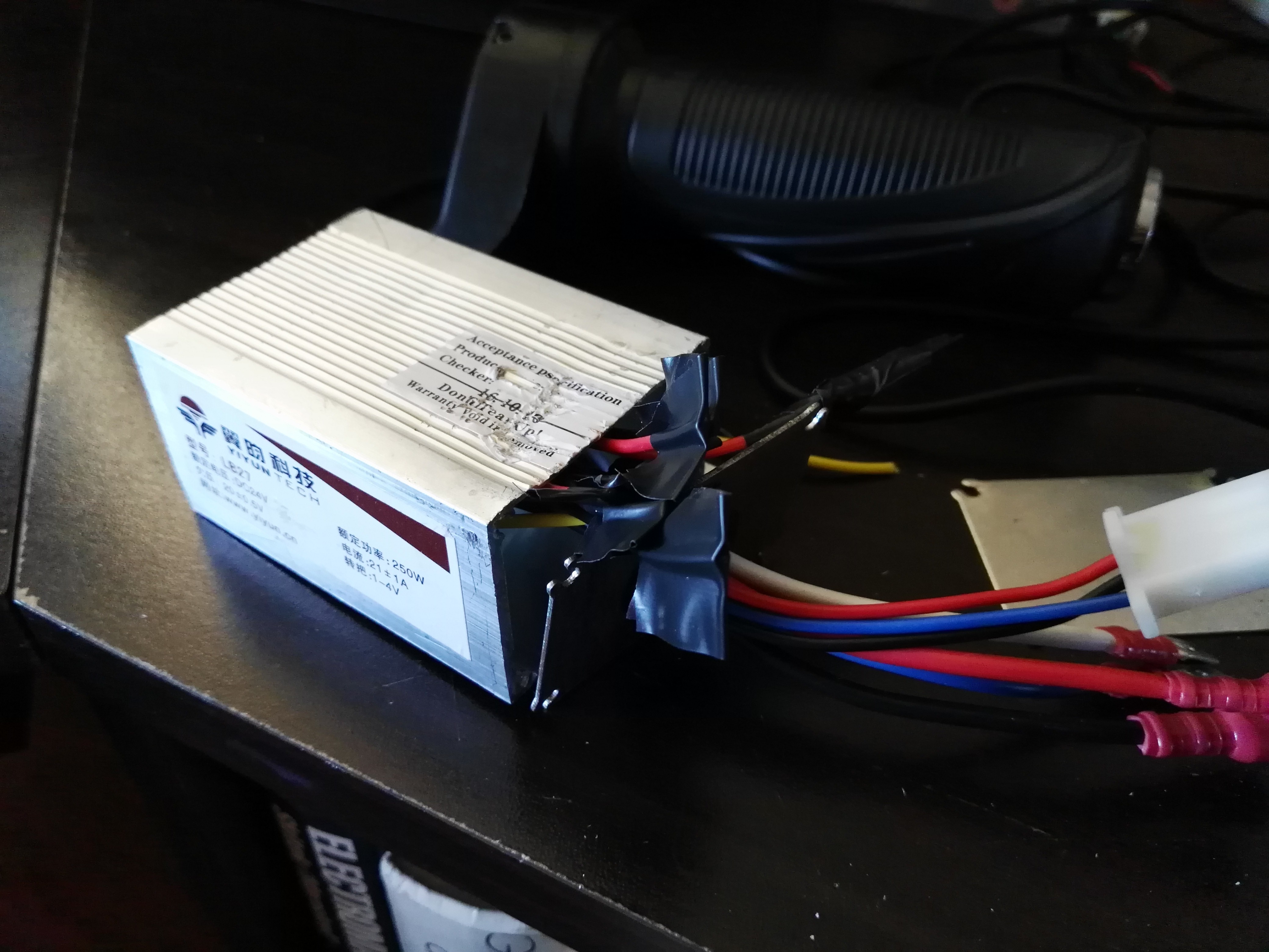
Cutting off the functions I don't need:
![]()
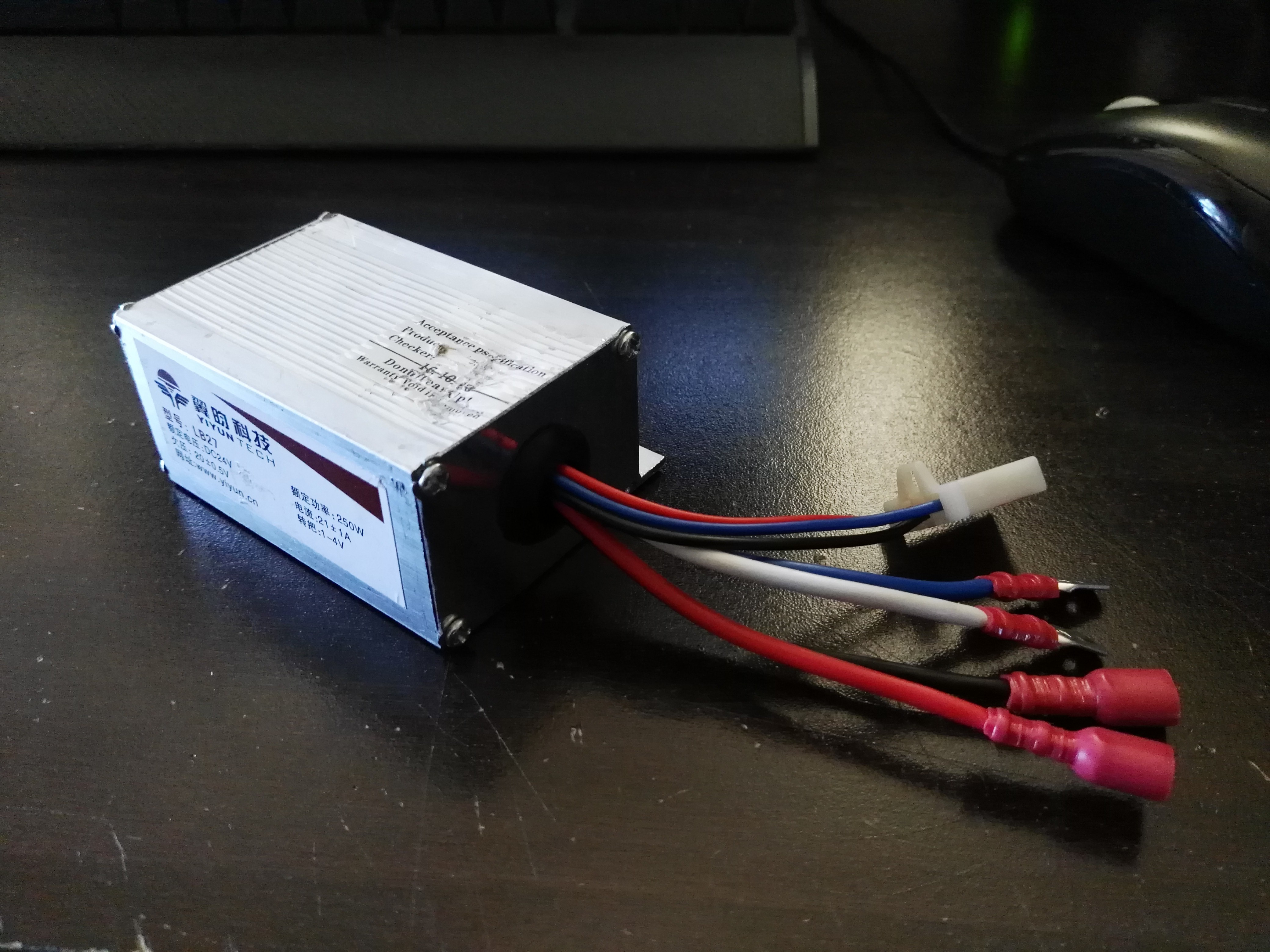
Sealing up the unit (only power, motor and throttle connections remain):
![]()
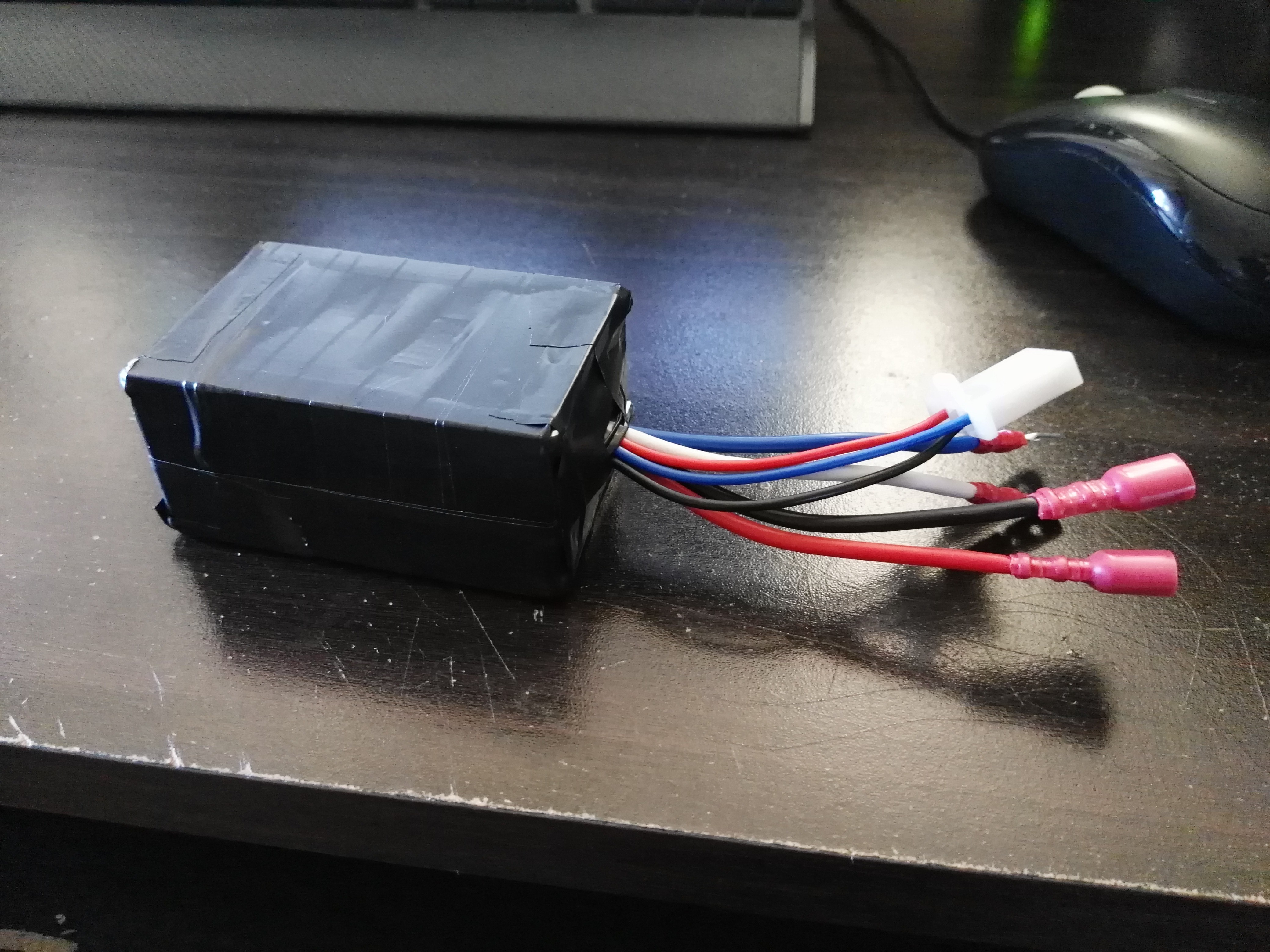
Electrical tape based water "proofing":
![]()
A test run of the motor:
-
Sorting Through the Parts! (V2 - Now With Pictures!)
04/20/2017 at 14:18 • 0 comments(I don't know how to edit project logs or delete them)
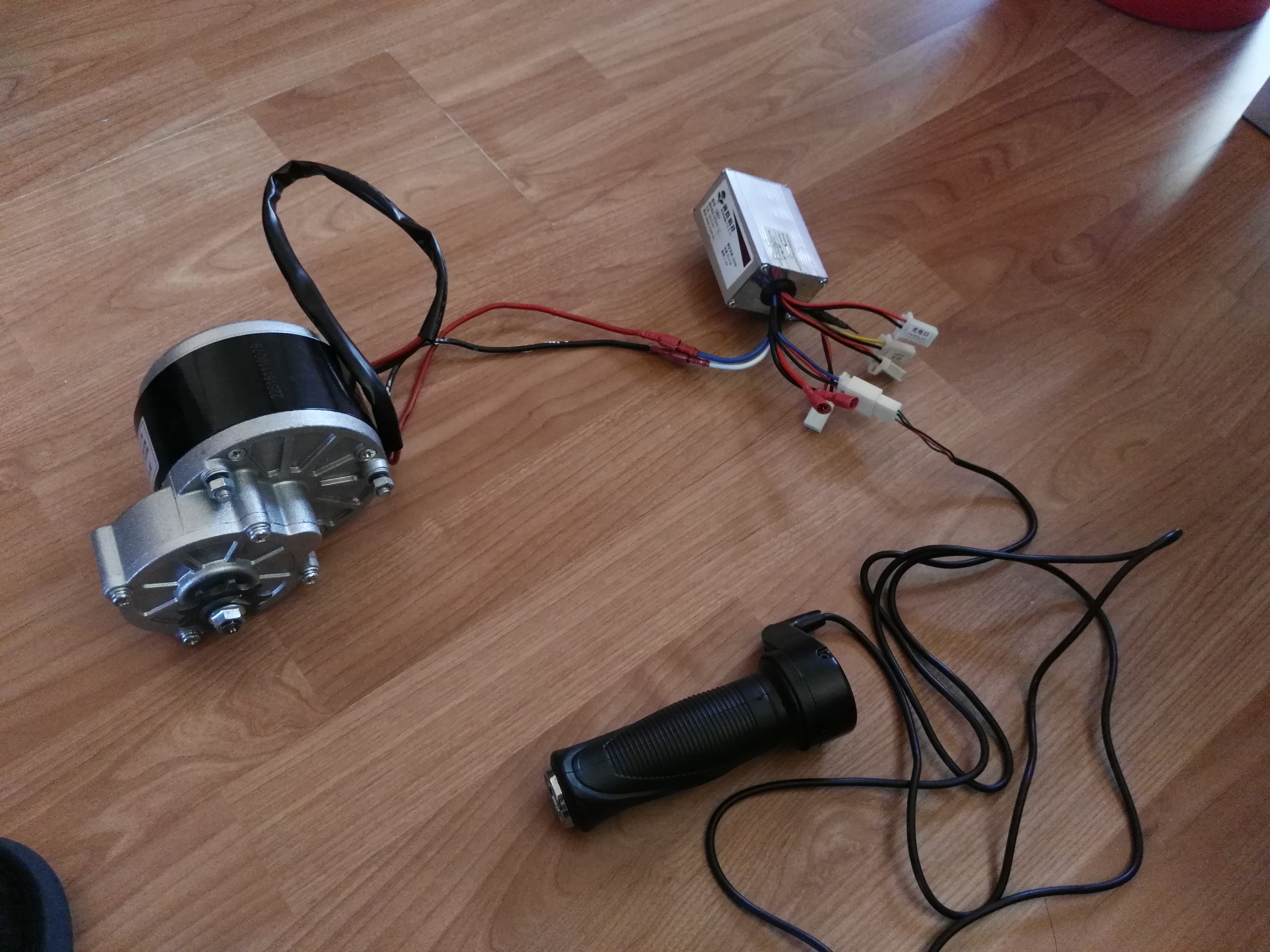
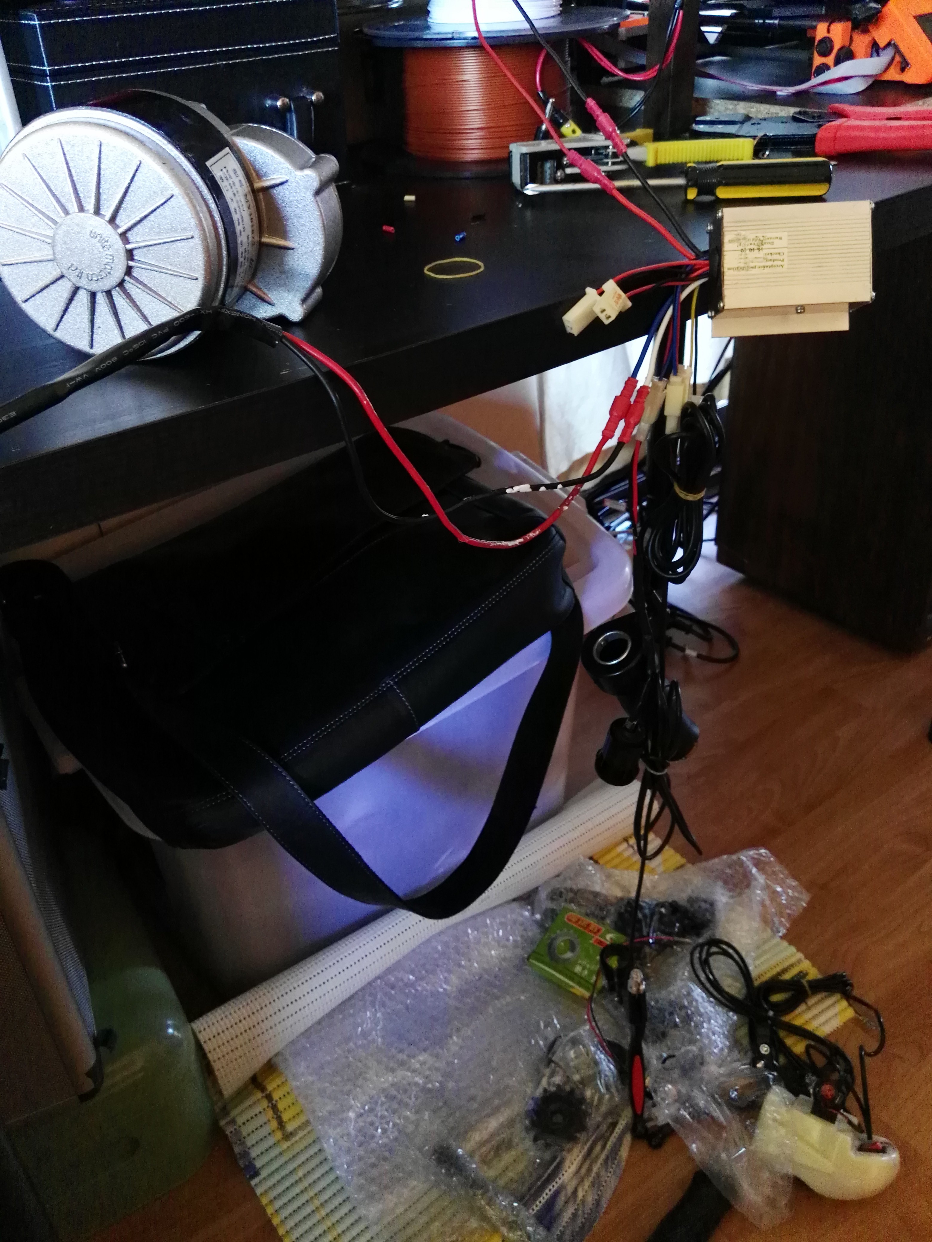
Slowly sorting through the parts now! The eBay kit came with a whole range of fun toys to play with:
- Throttle potentiometer
- Headlight/horn unit
- Two brakes with electrical switch output (for brake lights and motor braking)
- 24V DC motor
- 24V DC-DC motor controller (with many other functions specific to electric bicycles)
- Motor mount
- Key start switch
- Ratcheted mounting “thing”
- Bike chain to couple the motor
- Various mounting screws and accessories
![]() For my case I am interested in only the motor, DC-DC converter,
throttle control and anything that helps connect these devices to the bicycle.
For my case I am interested in only the motor, DC-DC converter,
throttle control and anything that helps connect these devices to the bicycle.
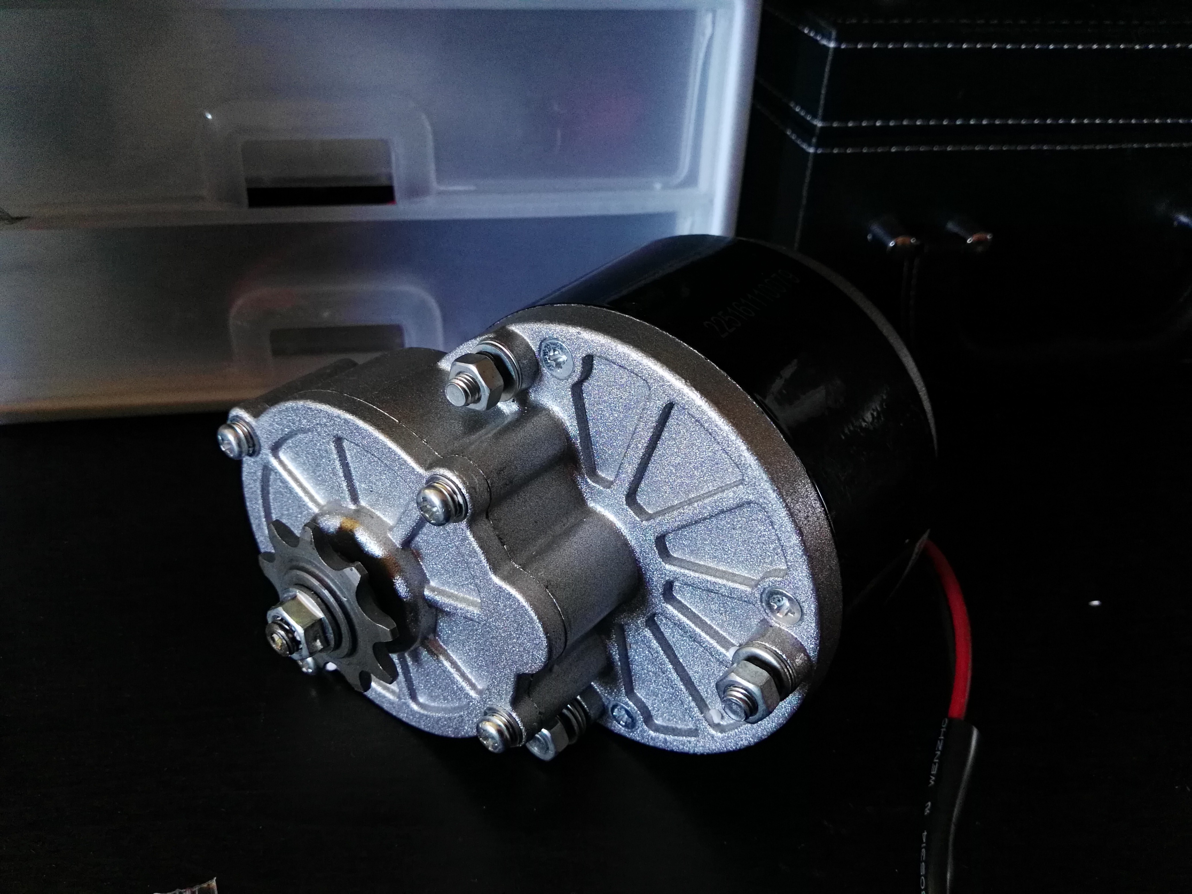
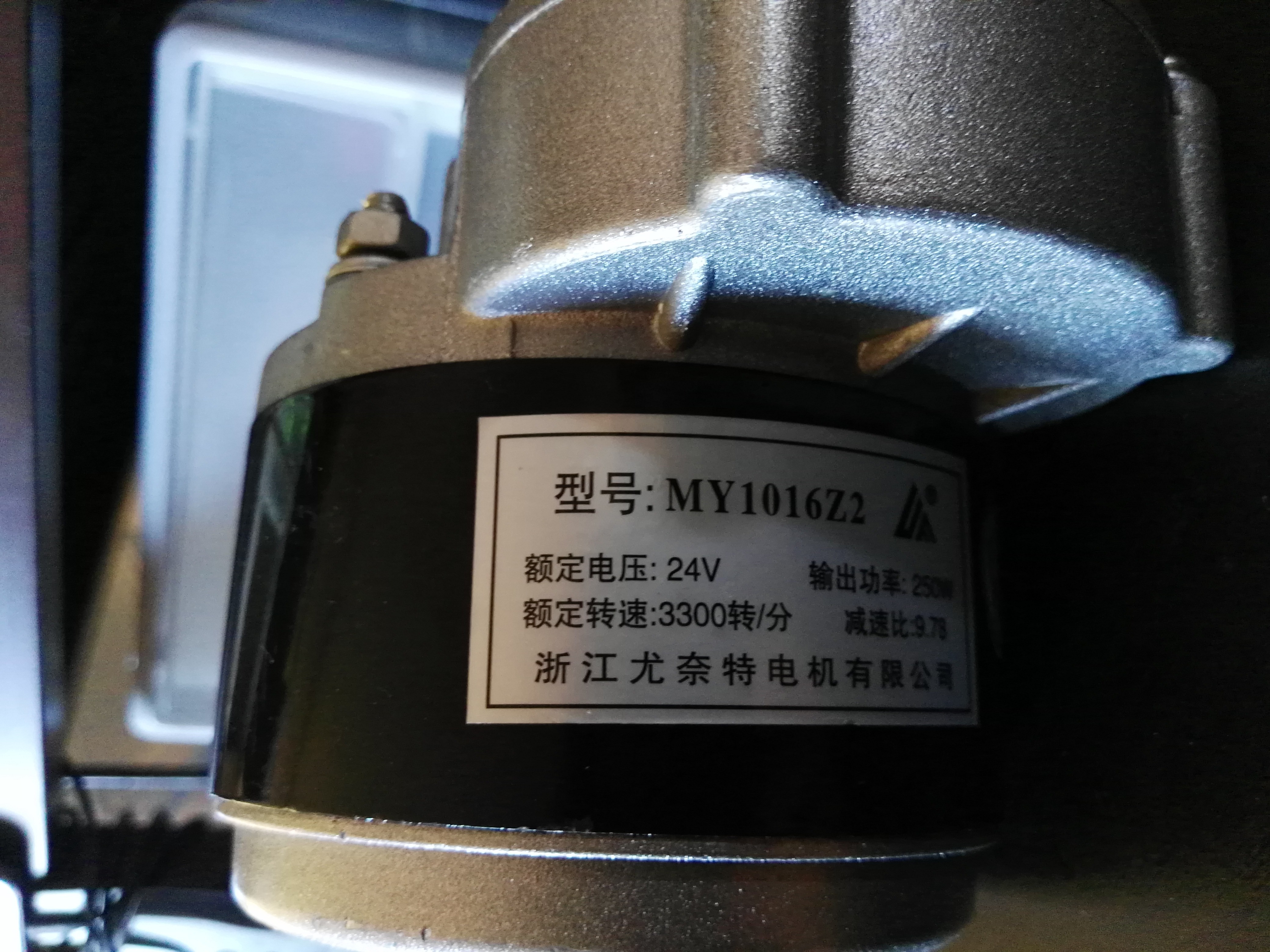
The motor is a 3000rpm 24V DC machine with an inbuilt step down gearbox with a 9.78:1 ratio. I have seen this exact motor in many auctions online, each claiming different power ratings (200W – 350W). It’s going to be fun seeing just how much current it will try to draw under load.![]()
![]()
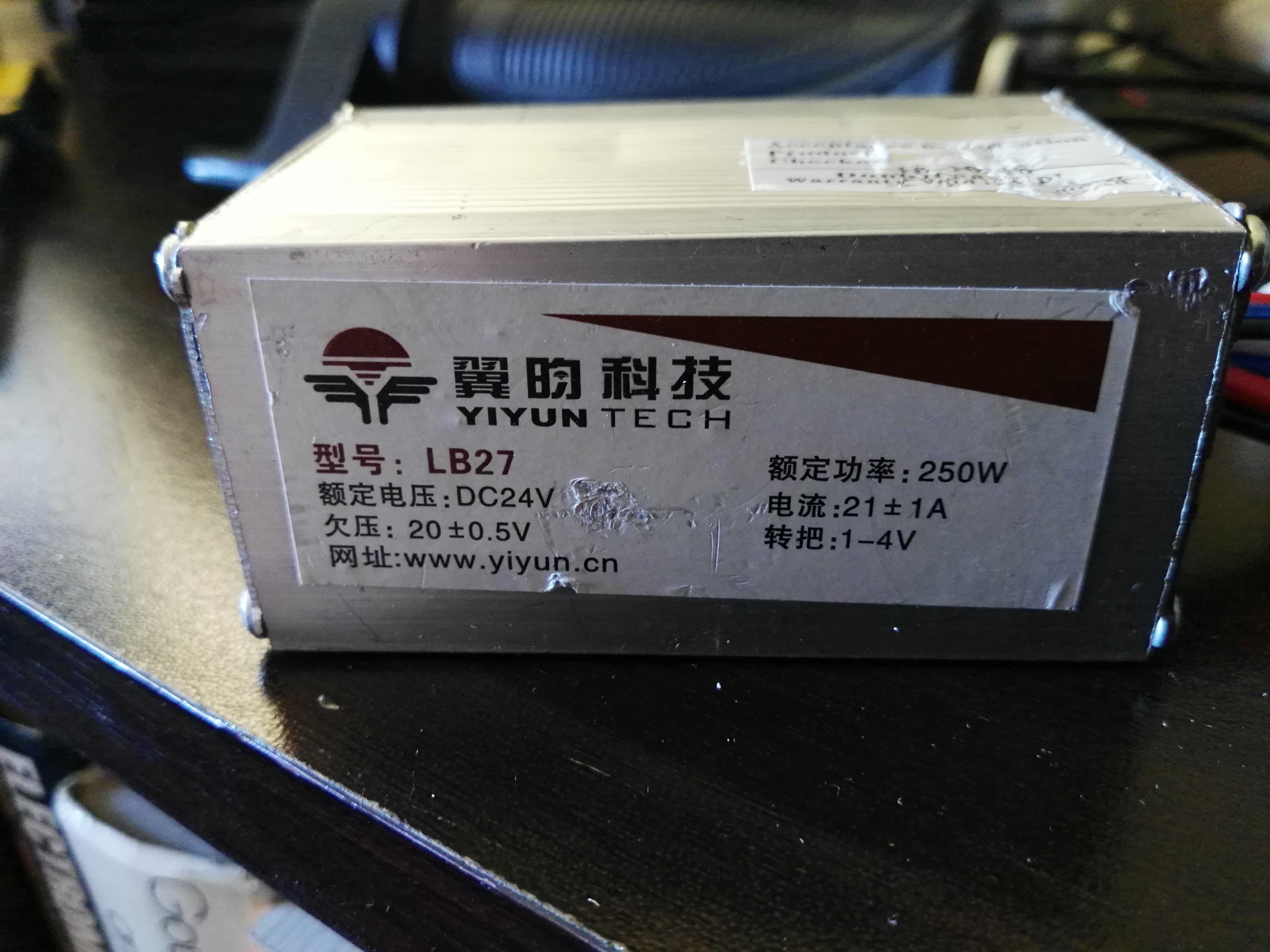
Similarly, the matching motor controller is a 24V DC-DC step down converter with a continuous current rating of 21A. It claims to be 250W, but it sounds more like 500W (peak at least). Interestingly if the voltage drops below 20V it reduces the output current instantly, but once the voltage rises back above 20V it will immediately try to run the motor again. Other motor controllers will sometimes shut off for ‘x’ seconds – an annoying feature when playing with “soft” voltage sources. The “1-4V” is for the throttle potentiometer voltage levels.![]()
![]()
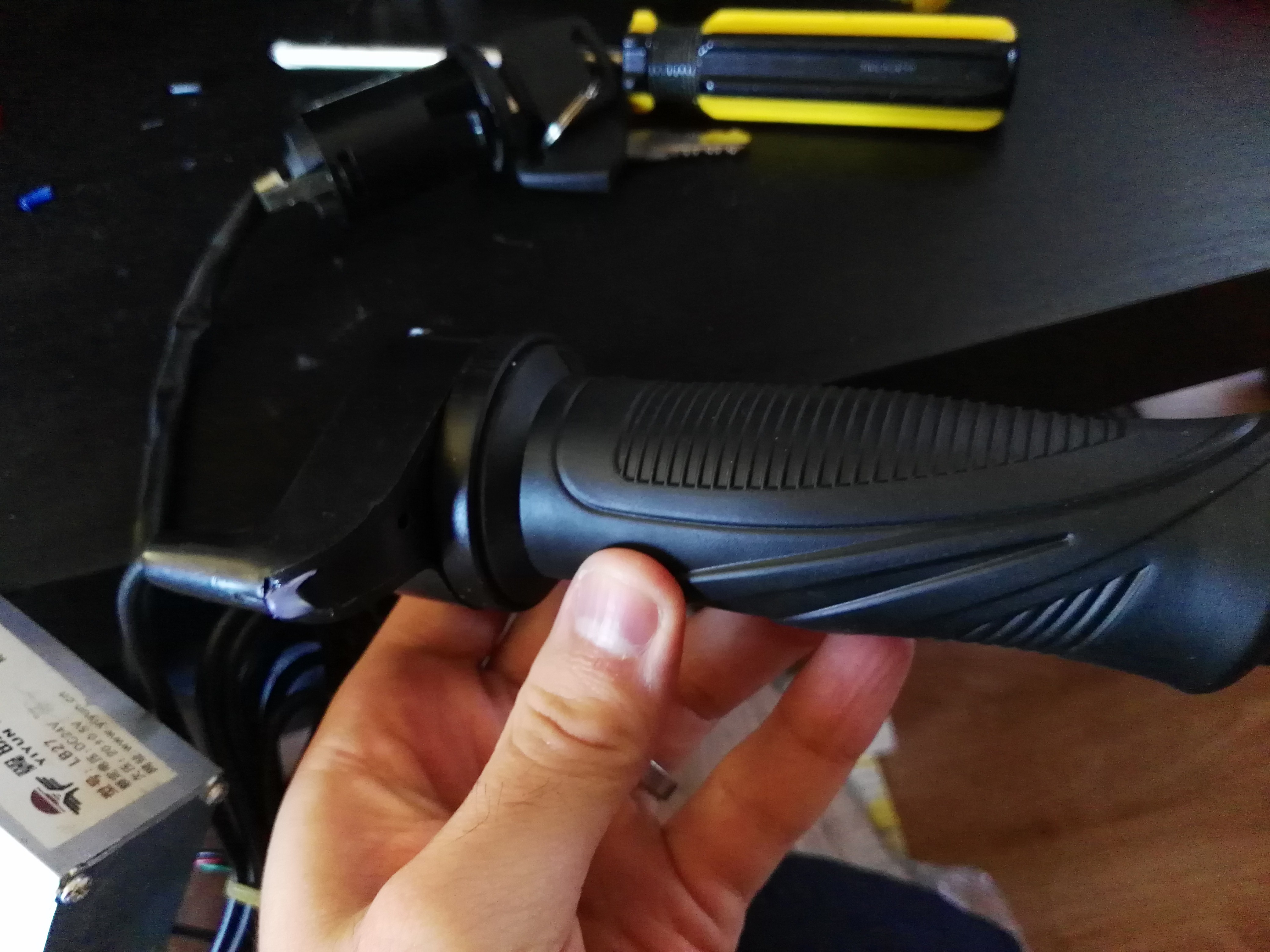
![]() The throttle
potentiometer up close:
The throttle
potentiometer up close:![]()
It seems to be nothing more than a potentiometer, though I am yet to actually measure its output with any instruments.
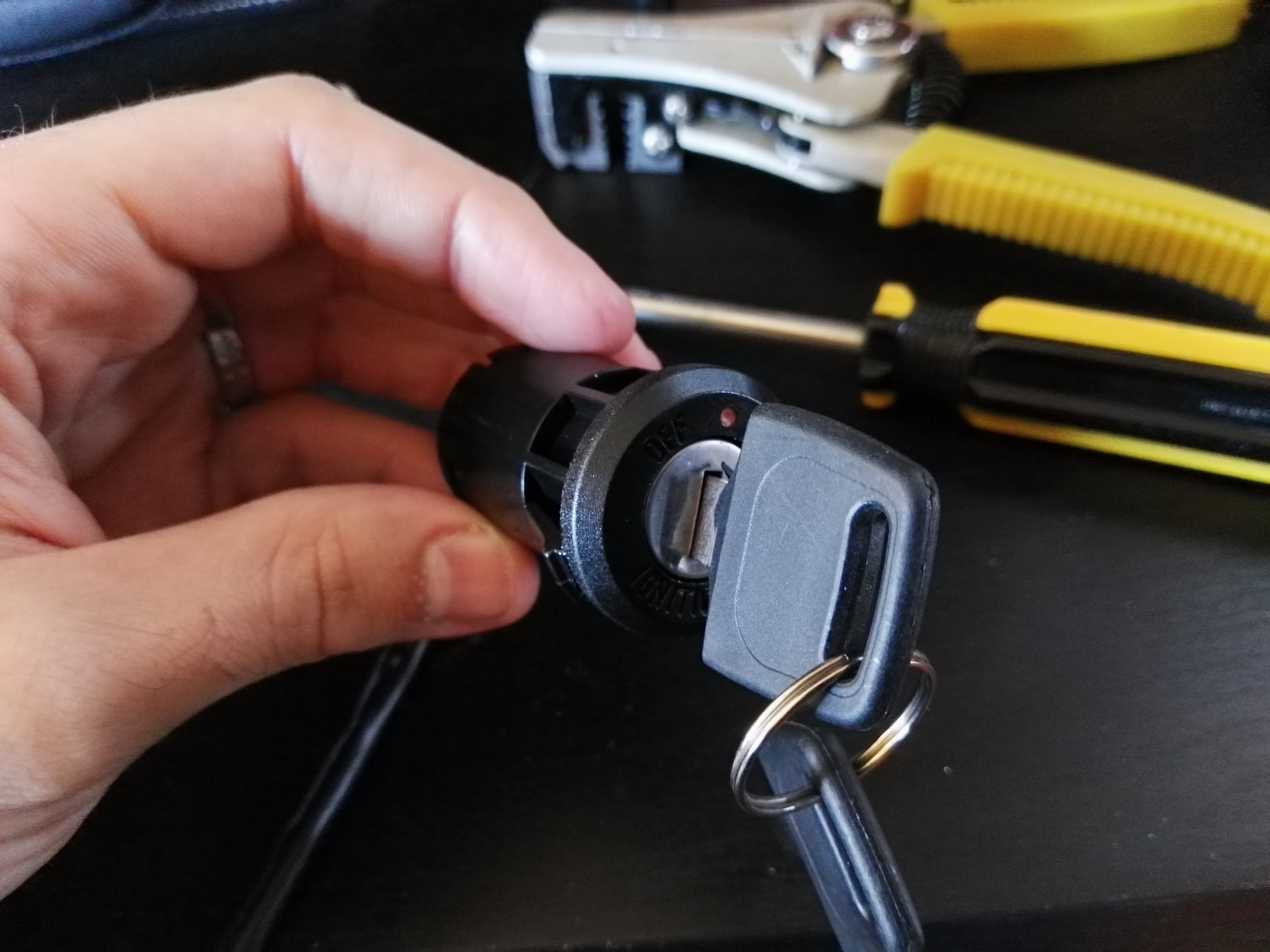
Next up is the key start switch. I have no idea how I’d mount this and it seems useless for the most part.
![]()
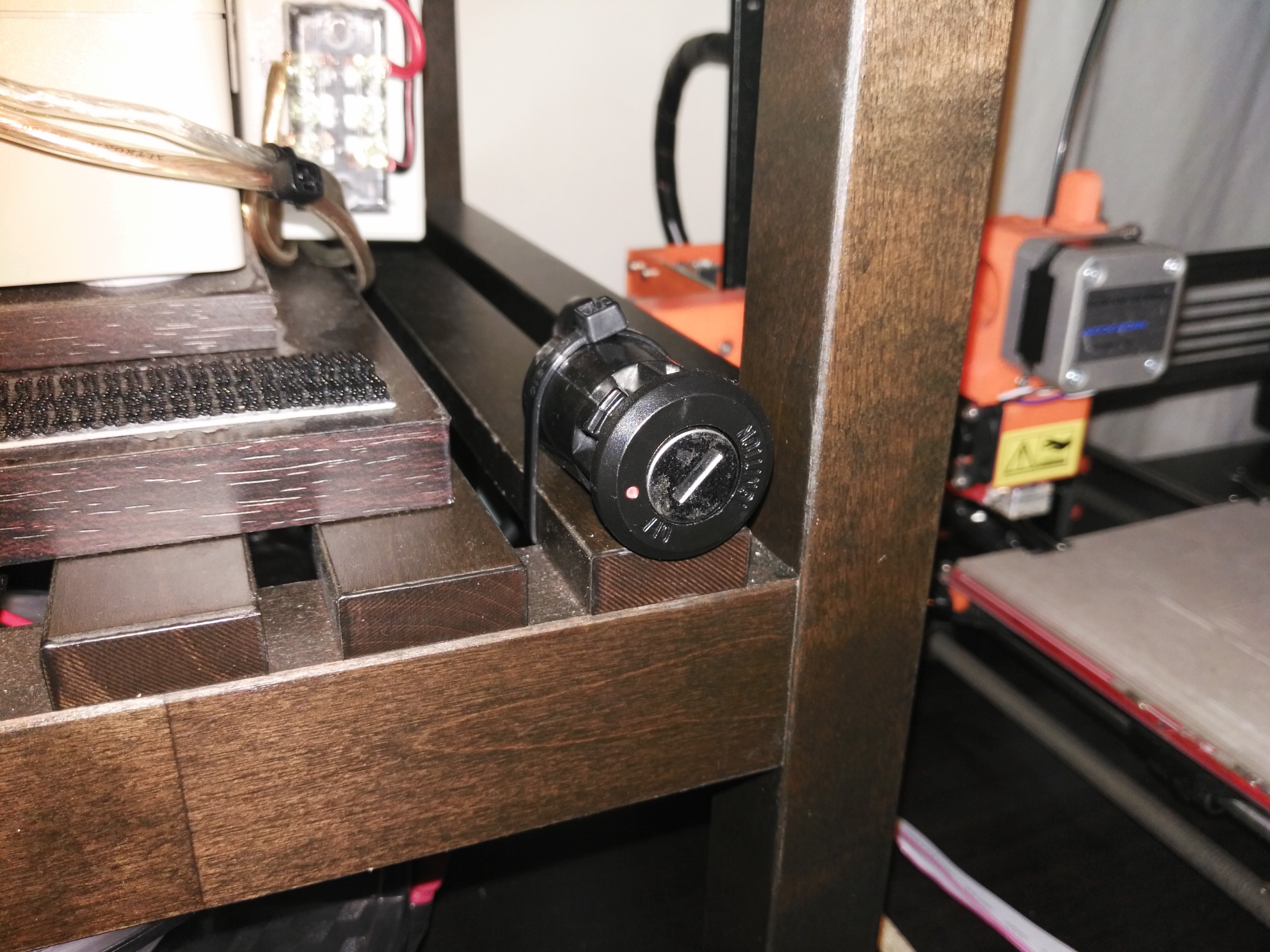
So instead I made it a switch to turn on my 3D printer:
![]()
-
Sorting Through the Parts!
04/20/2017 at 14:03 • 0 commentsSlowly sorting through the parts now! The eBay kit came with a whole range of fun toys to play with:
- Throttle potentiometer
- Headlight/horn unit
- Two brakes with electrical switch output (for brake lights and motor braking)
- 24V DC motor
- 24V DC-DC motor controller (with many other functions specific to electric bicycles)
- Motor mount
- Key start switch
- Ratcheted mounting “thing”
- Bike chain to couple the motor
- Various mounting screws and accessories
For my case I am interested in only the motor, DC-DC converter, throttle control and anything that helps connect these devices to the bicycle.
The motor is a 3000rpm 24V DC machine with an inbuilt step down gearbox with a 9.78:1 ratio. I have seen this exact motor in many auctions online, each claiming different power ratings (200W – 350W). It’s going to be fun seeing just how much current it will try to draw under load.
Similarly, the matching motor controller is a 24V DC-DC step down converter with a continuous current rating of 21A. It claims to be 250W, but it sounds more like 500W (peak at least). Interestingly if the voltage drops below 20V it reduces the output current instantly, but once the voltage rises back above 20V it will immediately try to run the motor again. Other motor controllers will sometimes shut off for ‘x’ seconds – an annoying feature when playing with “soft” voltage sources. The “1-4V” is for the throttle potentiometer voltage levels.
The throttle potentiometer up close:
It seems to be nothing more than a potentiometer, though I am yet to actually measure its output with any instruments.
Next up is the key start switch. I have no idea how I’d mount this and it seems useless for the most part.
So instead I made it a switch to turn on my 3D printer:
The 200W+ AA Battery Electric Bicycle
A 200W+ electric bicycle powered by a bank of regulated super capacitors that are charged by 10 AA batteries.
 David Scholten
 For my case I am interested in only the motor, DC-DC converter,
throttle control and anything that helps connect these devices to the bicycle.